1998 HONDA INTEGRA length
[x] Cancel search: lengthPage 641 of 1681

Driveshafts
Reassembly (cont'd)
7. Pack the inboard joint with the joint grease included
in the new driveshaft set.
Grease quantity: 120 - f30 g 11.2-4.6ozl
Fit the inboard joint onto the driveshaft.
NOTE:
. Reinstall the inboard joint onto the driveshaft by
aligning the marks on the inboard joint and the
ro ers.
. Hold the driveshaft so the inboard joint points up
to p.event it from falling off.
DRIVESHAFT
16-10
8.
9. Fit the joint boot ends onto the driveshaft and
Jornts.
When installing the outboard joint boot on a
Canada model, be sure the end of the boot is seated
in the grooves of the driveshaft and outboard ioint.
Adjust the length of the driveshafts to the specifica-
tions below, then adjust the boots to halfway
between full compression and full extension.
NOTE: The ends of boots seat in the groove of the
driveshaft and joint.
Lefr: 475 - 480 mm {18.7 - 18.9 inl
Right:475 - 480 rnm (18.7 - 18.9 int
10.
OUTBOARD BOOT {TPE)Canada AT modeloutboard joint only.
Page 706 of 1681

59.
Apply steering grease to the circumference of the
rack end housing.
Coat the rack end groove and inside of the boot
with silicone grease.
-Cl STEERTNG GREASE
SILICONE GBEASECoat the slidingsurface ofthe rack
end.
60.lnstall the boots in the rack end with the tube
clamps.
NOTE: Install the boots with the rack in the straight
ahead position (right and left tie-rods are equal in
length).
RACK END
TUBE CLAMP
17-57
ot.Adjust the air tube fitting position ot the boots by
turning it as shown below.
Connect the air tube between the right and left
boot, then install the clips on the cylinder line B as
snown.
Installthe righi clipin this position.
(cont'd)
mrn 11.57 - 1.97 inl
Page 765 of 1681

Master Cylinder/Brake Booster
I'RemovaUlnstallation
CAUTION: Do not spill brake tluid on the vehicle; it may
damage the paint; if brake fluid does contact the paint,
wash it oft immediatoly with water.
l. Disconnect the brake fluid level switch connectors.
2. Remove the reservoir cap from the master cylinder.
3. Remove the brake fluid from the master cvlinder
reservoir with a syringe.
4. Disconnect the brake lines from the master cylinder.
Be careful not to bend or damage the brake lines
when removing the master cylinder.
5. Remove the master cylinder mounting nuts and
washers.
6. Remove the master cylinder from the brake booster.
To prevent spills, cover the line joints with rags or
shoD towels.
7. Disconnect the vacuum hose from the brake booster.
8. Remove the lock pin and clevis pin from the clevis.
Do not disconnect the clevis by removing it from
the operating rod of the brake booster. lf the clevis
is loosened, adjust the pushrod length before
installing the brake booster.
13 N.m (1.3 kgf'm, 9 lbl'ft)
LOCX PIN
9. Remove the four booster mounting nuts.
10. Pull the brake booster forward until the clevis is
clear of the bulkhead.
11. Remove the brake booster from the enqine com-
panmenL
12, Install the brake booster and master cylinder in the
reverse order of removal and note these items:
. When connecting the brake lines, make sure that
there is no interference between the brake lines
and other parts.
. Be careful not to bend or damage the brake lines
when installing the master cylinder.
. lf replacing the master cylinder or brake booster,
check and adiust the DUshrod clearance before
installing the master cylinder (see page 19-14).
13. Fill the master cylinder reservoir, and bleed the
brake system (see page 19-7).'14. After installation, check the brake pedal height and
brake pedal free play and adjust if necessary (see
page 19-5).
BRAKE FLUID LEVEL
SW]TCH CONNECTORS
MASTER CYLINOERVACUUM HOSE
J
15 N.m t1.5 kgl'm, 11 lbf'ft)
Page 767 of 1681

1.
8.
NOTE: lf the clearance between the gauge body
and adjusting nut is 0.4 mm (0.02 in), the pushrod-
to-piston clearance is 0 mm. However, if the clear-
ance between the gauge body and adjusting nut is
0 mm, the pushrod-to-piston clearance is 0.4 mm(0.02 in) or more. Therefore it must be adjusted and
rechecked.
lf clearance is incorrect, loosen the star locknut and
turn the adjuster in or out to adjust.
NOTE:
. Adjust the clearance while the specified vacuum
is applied to the booster.
. Hold the clevis while adjusting.
Tighten the star Iocknut securely.
Remove the special tool.
0 - o.il mm l0 - 0.02 inl
Brake Booster Inspection
Functions Tgst
1. With the engine stopped, depress the brake pedal
several times to deplete the vacuum reservoir, then
depress the pedal hard and hold it for 15 seconds. ll
the pedal sinks, either the master cylinder is
bypassing internally; or the brake system (master
cylinder, lines, modulator proportioning valve, orcaliper) are leaking.
Start the engine with the pedal depressed. lf thepedal sinks slightly, the vacuum booster is operat-
ing normally. lf the pedal height does not vary, the
booster or check valve is faulty.
With the engine running, depress the brake pedal
lightly. Apply just enough pressure to hold back
automatic transmission creep, lf the brake pedal
sinks more than 25 mm (1.0 in.) in three minutes,
the master cylinder is faulty. A slight change inpedal height when the A,,/C compressor cycles on
and off is normal. (The A/C compressor load
changes the vacuum available to the booster.)
Leak Test
1. Depress the brake pedal with the engine running,
then stop the engine. lf the pedal height does not
vary while depressed for 30 seconds, the vacuum
booster is OK. lf the pedal rises, the booster is
fau lty.
2. With the engine stopped, depress the brake pedal
several times using normal pressure. When thepedal is first depressed, it should be low. On con-
secutive applications, the pedal height should grad-
ually rise. lf the pedal position does not vary, check
the booster check valve.
Boostor Ch€ck Valve T6st
1. Disconnect the brake booster vacuum hose at the
booster,
Start the engine and let it idle. There should be vac-
uum available. It no vacuum is available. the check
valve is not working properly. Replace the brake
booster vacuum hose and check valve, and retest.
VACUUM HOSE(Check valve built-in)
STAR LOCKNUT22 t{.m12.2 ksl.m, 16lbf.ftl
cLEVtS
ADJUSTER
ADJUSTMENT GAUGE07JAG - SD40t00
9. Adjust the pushrod length as shown if the booster
is removed.
1161 0.5 mm14.61 0.02 inl
PUSHRODLOCKNUT15 N m 11.5 kgf m, 11 lbf'ftl
10. Instali the master cylinder.
Page 1139 of 1681

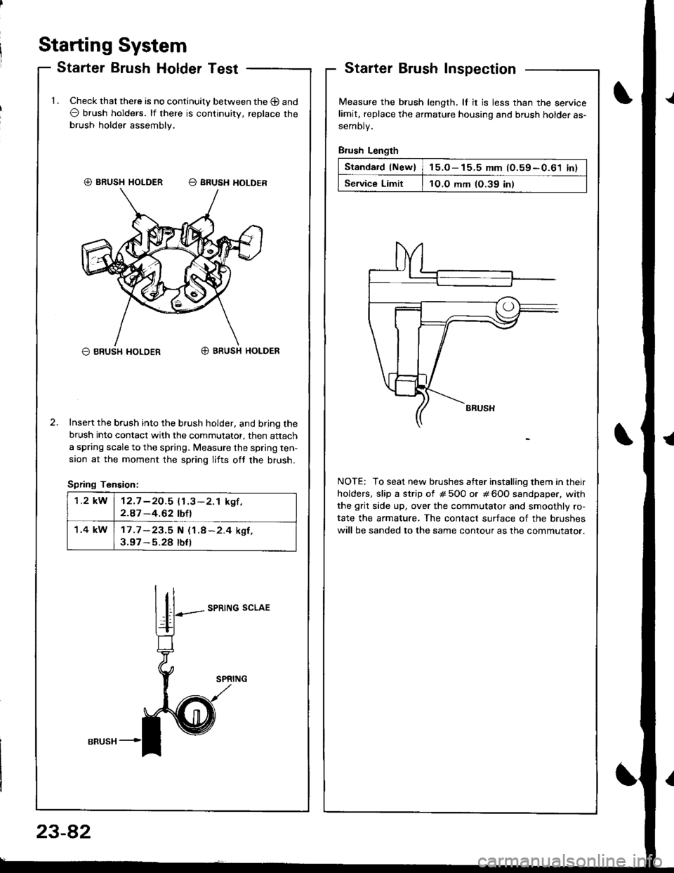
Staning System
Starter Brush Holder TestStarterInspection
Measure the brush length. lf it is less than the servicelimit, replace the armature housing and brush holder as-
semoty.
Brush Length
Standard lNew)15.o- 15.5 mm (O.59-0.61 inl
Service Limit1O.O mm (O.39 in)
NOTE: To seat new brushes atter installing them in their
holders, slip a strip of # 5O0 or # 600 sandpaper, with
the grit side up, over the commutator and smoothly ro-
tate the armature, The contact surface of the brushes
will be sanded to the same contour as the commutator.
1.Check that there is no continuity between the O and
O brush holders. lf there is continuitv, replace the
brush holder assembly.
O BRUSH I{OLDERO BRUSH HOLDER
Insert the brush into the brush holder, and bring the
brush into contact with the commutator, then attach
a spring scale to the spring. Measure the spring ten-
saon at the moment the spring lifts ott the brush.
Spring Tension:
SPRING SCLAE
€) BRUSH HOLDER O SRUSH HOLDER
1.2 kW12.7 -2O.5 11.3-2.1 kgf ,2.A7 -4.62 tbtl
1.4 kW17 .7 -23.5 N (1.8*2.4 ksf ,3.97 - 5.28 tbfl
I
23-82
Page 1166 of 1681

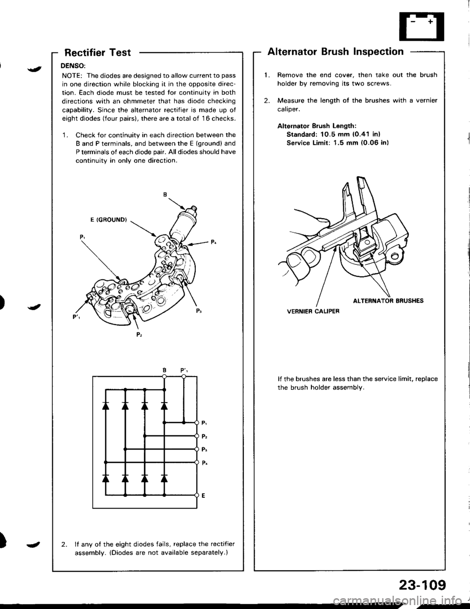
RectifierTest
DENSO:
NOTE: The diodes are designed to allow current to pass
in one direction while blocking it in the opposite direc-
tion. Each diode must be tested tor continuity in both
directions with an ohmmeter that has diode checking
capability. Since the alternator rectifier is made up ot
eight diodes (four pairs), there are a total of 16 checks.
'1. Check for continuity in each direction between the
B and P terminals, and between the E (ground) and
P terminals of each diode pair. All diodes should have
continuity in only one direction.
lf any of the eight diodes fails, replace the recti{ier
assembly. iDiodes are not available separately.)
2.
AlternatorBrushInspection
l.Remove the end cover, then take out the brush
holder by removing its two screws.
Measure the length of the brushes with a vernier
caliper.
Altelnator Brush Length:
Standard: 1O.5 mm {O.41 in}
Service Limit: 1.5 mm (0.06 in)
2.
lf the brushes are less than the service limit, replace
the brush holder assembly.
VERNIER CALIPER)
{
J
)
23-109
J
.-
Page 1170 of 1681

i'[
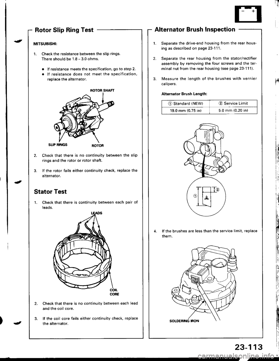
Rotor Slip Ring TestAlternator Brush Inspection
Separate the drive-end housing from the rear hous-
ing as described on page 23-l 1 1.
Separate the rear housing from the stator/rectifier
assembly by removing the four screws and the ter-
minal nut from the rear housing (see page 23-111).
Measure the length of the brushes with vernier
calrpers.
Alternator Brush Length:
O Standard (NEW)O Service Limit
19.0 mm (0.75 in)5.0 mm (0.20 in)
lf the brushes are less than the service limit, replace
them.
23-113
{
J
lFr
MITSUBISHI:
1. Checkthe resistance between the slip rings.
There should be 1.8 - 3.0 ohms.
. lf resistance meets the specification, go to step 2,
. lf resistance does not meet the specification,
replace the alternator.
SLIP RII{GS
Check that there is no continuity between the slip
rings and the rotor or rotor shaft.
lf the rotor fails either continuity check, replace the
alternator.
Stator Test
1. Check that there is continuity between each pair of
leads.
co|LconE
Check that there is no continuity between each
and the coil core.
lf the coil core fails either continuity check, replace
the alternator.
ROIOR SHAFT
J
"-
Page 1644 of 1681

I
I
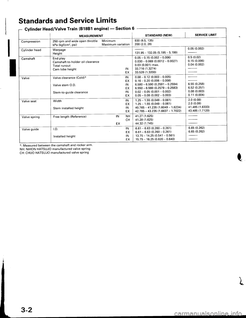
Standards and Service Limits
Cylinder Head/Valve Train (B18Bl engine)Section 6
*: Measured between the camshaft and rocker arm.
NH: NIHON HATSUJO manufactured valve spring
CH: CHUO HATSUJO manufactured valve spring
MEASUREMENTSTANDARD (NEW) I SERVICE LIMIT
Compression250 rpm and wide open throttle Minimum
kPa (kgf/cm'�, psi) Maximum variation930 (9.5, 135)200 Q.0,281
Cylinder headWarpageHeightta,|* - 132.05 (5.195 - 5.199)0.05 (0.002)
CamshaftEnd playCamshaft-to-holder oil clearanceTotal runoutCam lobe height lNEX
0.05 - 0.15 (0.002 - 0.006)0.030 - 0.069 (0.0012 - 0.0027)0.03 (0.001) max.33.7 16 11.327 4l33.528 ( 1.3200)
0.5 (0.02)
0.15 (0.006)
0.04 (0.002)
ValveValve clearance (Cold)" lNEX
Valve stem O.D. lNEX
Stem-to-guide clearance lNEX
0.08 - 0.12 (0.003 - 0.005)0.16 - 0.20 (0.006 - 0.00816.580 - 6.590 (0.2591 - 0.2594)6.550 - 6.560 (0.2579 - 0.2583)
0.02 - 0.05 (0.001 - 0.002)0.05 - 0.08 (0.002 - 0.003)
ouu to.rutt6.52 rc.2571.0.08 (0.003)
0.1 1 (0.004)
Valve seatwidth lNEX
stem installed height lNEX
1 .25 - 1.55 (0.049 - 0.061 )1.25 - 1 .55 (0.049 - 0.061 )40.765 - 41.235 (1.6049 - 1.6234142J65 - 43.235 (1.6837 - 1.70221
2.0 (0.08)
2.0 (0.08)
41.485 (1.6333)
43.485 (1.71201
Valve springFree length (Reference)IN NHCHEX
41.27 (1.6251
41.28 (1.625)
44.32 t1-7 451
Valve guidet.D. lNEX
Installed height lNEX
6.61 - 6.63 (0.260 - 0.261)6.61 - 6.63 (0.260 - 0.261)13.7 5 - 1 4.25 (0.541 - 0.561 )15.75 - 16.25 (0.620 - 0.640)
6.6s (0.262)
6.65 (0.262)