Page 257 of 1681

PGM.FISystem
Gontrol Module (ECMI (cont'dlEngine
\
L
(From page 11-51)
Choc* tol s short in tho wir6 lMlLlino):1. Turn the ignition switch OFF.2. Disconn€ct the ECM conn6c-tor A (32P).
3. Turn the ignition switch ON (ll).
Repair 3hon to body ground in
rhe wire bstw.on tho ECM (A181
and MlL.
Substituto s known-good ECMend rechock. H 3ymptom/indica-tion goes awry, replacc tho origi-nelECM,
{From page 11-51)
Inspect Fl E/M (15 A) fuse in theunder-hood Iuse/relay box.
- Ropsir short in tha wircbotw.on Fl E/M {'15 Al tu3c'rnd PGM-FI m.in t.lry.- Rool.c. Fl E/M l15A)tu!€.
Inspect No. 13 FUEL PUMP (SRS
UNIT) ('l5A) fuse in the undeFdash fuse/relay box.
- Reo.ir sholt in th. wirobotw..n No. 13 FUEL PUMP
{SRs UNIT) (15 Al fur..ndFGM-FI m.in rclay.- Repl.co No. 13 FUEL PUMP(SRS UNIT) {15 Alturr.
Ch6ck for . shon in a son3or1. Turn the ignition switch ON (ll).
2. Disconnect the 3P connectorfrom oach sensor one at time:. MAP sensor. TP sensor. Fueltank pressure sensor
Rapl.cc tha 3onaor thrt cauaadihe light to 9o out.Does the MIL go OFF?
1-52
(To page 11-53)
Page 280 of 1681

(From page 11-74)
Check tor an op6n in the wire{lGP, lGl* linel:Measure voltage between No. 3terminal and body ground.
Repair open in the wirebetween PGM-Fl mein relayand Pii.nary HO2S {Sonsor 11.Repair open in the wirebetween No. 15 ALTERNATORSP SENSOR 17.5 A) tuse in theund€r-d.sh fuse/rolav box andSecondary HO2S (S€n3or 21.
ls there battery vohage?
Check for an opon in the wh$:1. Turn the ignition switch OFF.2. Reconnect the HO2S connec-tor.3- Disconnect the ECM connectorA (32P).
4. Turn the ignition switch ON 1fl).5. Measure voltage between theECM connector terminals 46or A5* and A10.
Repair open in tha wire betw.enECM {A6 or A5rl and HO2S.ls there 0.1 V or less?
Substitute a known-good ECMand r.chcck. tf 3ymptom/indica-tion goes awey, repl.ce the odgi-nelECM.
PRIMARY HO2S {Sensor 1} CONNECTOR C113SECONDARY HO2S (Sensor 2ICONNECTOR C45tr
Wire side of female terminals
ECM CONNECTOR A I32P)
IGPlG1
so2HTC{GRN/RET
c
4tr
A, 4\'/ | PO2HTC \=/ \ltoRN/BLKt \-T--] \
PGl(BLK)
2a 1f lefil tt12't5t51? t8t92022 23
2526l2823
Wire side of temale terminals
(From page '11-74)
Check fo. a short in the wire(O2SHTC linel:1. Turn the ignition switch OFF.2. Disconnect the ECM connec-tor A (32P).
3. Check for continuity betweenthe ECM connector 46 or A5*termanai and body ground.
Rcpair short in the wire botweenECM IAG or A5*l .nd HO2S.ls there continuity?
Substituto a known-good ECMand recheck. lf symptom/indica-tion goes away, replac€ the origi-nalECM.
3 rl 15 6
15 15 17 lA
*r P0141
11-75
Page 308 of 1681

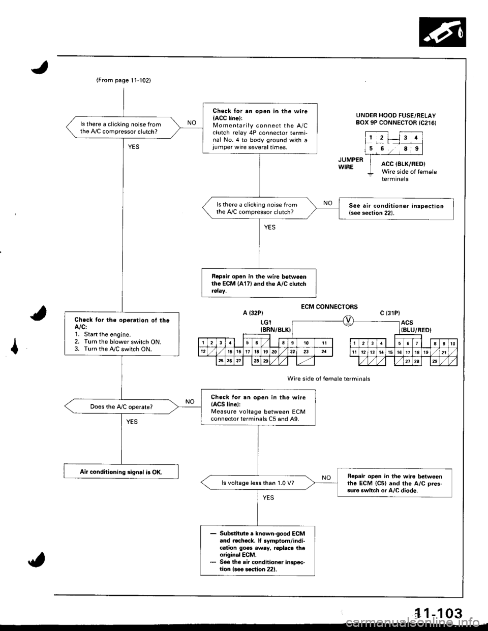
(From page t 1'102)
Ch6ck {or an op6n in the wireIACC linel:Mo m enta rily connect the A/Cclutch relay 4P connector termi-nal No. 4 to body ground with a,umper wire several times.
ls there a clicking noise fromthe A,/C compressor clutch?
ls there a clicking noise fromthe 4,./C compressor clutch?See air conditione. insoection{s€e section 22).
Repai. op6n in the wire betwe€ntho ECM lA17l and the A/C clutch
Check tor the oparation of theA/C:1. Start the eogine.2. Turn the blower switch ON.3. Turn the !y'C switch ON.
Check lor sn open in th6 wireIACS line):Measure voltage between ECMconnector terminals C5 and A9,
Air conditioning signal i3 OK.Repafu open in the wire betweenthe ECM {C5} and th€ A/C D.es-sure switch or A/C diode.
ls voltage less than 1.0 V?
- Substitute e known-good ECM.nd .echeck. lf 3ymptom/indi-cation goes away, rcplaco th€original ECM.- 56€ the air conditionor inspcc-tion {3eo soction 221.
UNDER HOOD FUSE/RELAYBOX 9P CONNECTOR tC216)
JUMPERWIREACC {SLK/RED)Wire side of temale- terminals
A {32P)
LGl(BRN/BLKI
ECM CONNECTORS
Wire side of female terminals
c (31P)
ACS{BLU/RED}
I
'1.1-103
Page 309 of 1681
This signals the ECM when the brake pedal is depressed
Inspeclion ot Brake Switch Signal.
Are the brake lights on withoutdepressing the brake pedal?
lnspect the HoRN STOP (20 Aifuse in the under-hood fuse/ relaybox,Do the brake lights come on?
Repair shori in the wire b€-
tween the brake switch and
the HoRN STOP {20 Al fuse.Replace tha HORN STOP (20 AlIus€.
Repair open in the wire be-tween the brtke switch andtho HORN STOP {20 Al tuse.
Inspect the brake switch {seesection 23).Check tor an open in the wire
{BKSW line):1- Depress the brake pedal.
2. Measure voltage between ECMconnector terminals D5 and Agwith the brake pedal depressed.
Repair open io th6 wiae batweonthe EcM lDs) rnd the brakeswitch.
Brake switch signal is OK.
ldle ControlSystem
Brake SwitchSignal
L
L
A {32P}LGl{BRN/BLX}
D {16P)
Wrre side of female terminals
I
Page 310 of 1681
Starter Switch Signal
This signals the ECM when the engine is cranking.
NOTEI. M/T:Clutch pedal must be depressed.. A,/T: Transmission in E or E position.
Wire sida of female terminals
Check for an opon or short in thcwi.. ISTS lin.l:Measure voltage between ECMconnector terminals C6 and Agwith the ignition switch in thostart position (lll).
Inspect the No.31 STARTER SIG-NAL (7.5 Alluse in the under-dashfuse/relay box,
ls there battery voltage?
- Repair 3hort in the wire be-tween tho ECM lc6l rnd theNo. 31 STARTER SIGNAL (7.sAl tus€ or the PGM-FI mainr€lay.- Roplace the No. 31 STARTERSIGNAL 17.5 Al fuso.
Starter switch signal b OK.
Ropair open in tho wire botwaonih6 ECM {CGl and the No, 3lSTARTER SIGNAL {7.5 Al fuse.
11-105
Page 330 of 1681

I
tr,
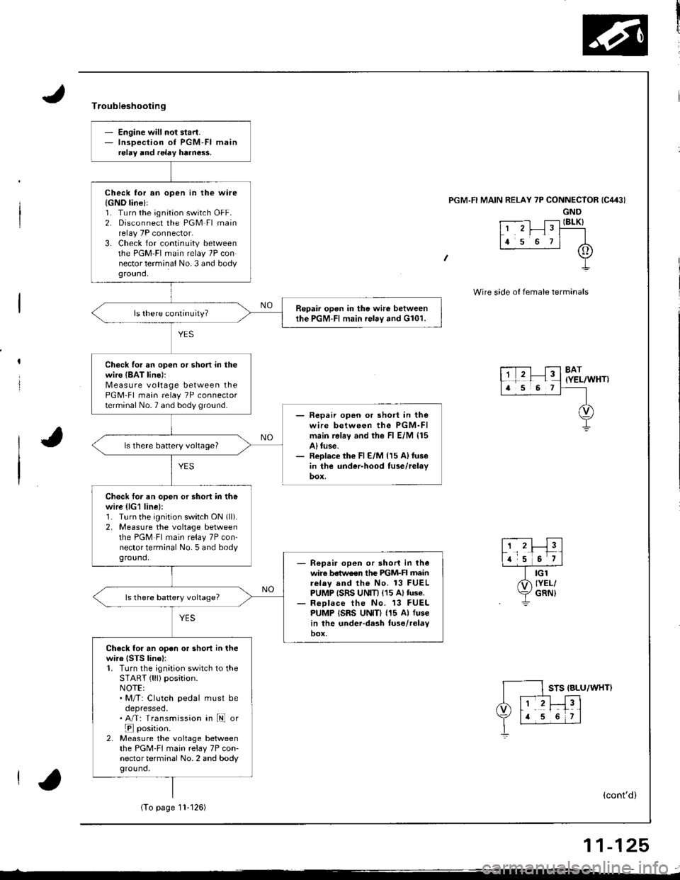
- Engine will not start.- Inspection of PGM-FI mainrelay and relay harne$.
Check lor an open in the ware{GND line}l1. Turn the ignition switch OFF.2. Disconnect the PGM Fl mainrelay 7P connector.3. Check for continuity betweenthe PGM'FI main relay 7P connector terminal No. 3 and bodyground,
Repair open in the wire betweenthe PGM-Fl main relay and G101.
Check for an open or shon in thewire {BAT line)rMeasure voltage between thePGM-Fl main relay 7P connectorterminal No.7 and body ground.- Fepaii open or short in thewire between the PGM-FImain rel6y and the Fl E/M 115A) tuse.- Replace th€ Fl E/M {15 A)fusein the under-hood tuse/relay
ls there battery vohage?
Check foi an open or shori in thewire (lG1 line):1. Turn the ignition switch ON (ll).
2, Measure the voltage betweenthe PGM Fl main relay 7P con-nector terminal No. 5 and bodyground,R€pair open or short in thewire betwo€n the PIGM-FI mainrelav and the No. 13 FUELPUMP ISRS UNIT) (15 Altuse.ReDlace the No. 13 FUELPUMP ISRS UNID (15 Al fusein the under-dash tuse/relayoox,
Check for an open or short in thewire {STS linel:1. Turn the ignition switch to theSTART { lll) position.NOTE:. M/T: Clutch pedal must beoepresseo.. A/T: Transmission in ld or
E position.2. Measure the voltage betweenthe PGM-FI main relay 7P con-nector terminal No. 2 and bodyground,
Troubleshooting
'l RELAY 7P CONNECTOR
GND
t .--.-l T;-l IBLK)L' 'r I" T----
lr s o rl A
+
Wire side o{ female termanals
8AT(YEL/WHT)
STS {BLU/WHTI
(cont'd)
(To page11- t 26)
11-125
Page 331 of 1681

F
I
Fuel Supply
PGM-Fl Main
System
Relay (cont'd)
\
lb
i
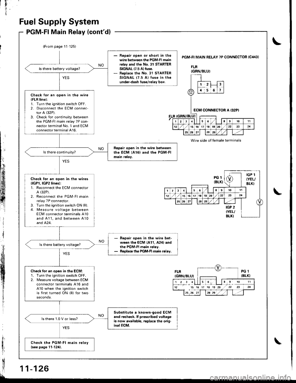
(From page 11 125)
- Reprir open or short in thewire between the PGM-FI mainrelay and the No. 31 STARTERSIGNAL {7.5 A} tuse.- RoDlace the No. 31 STARTERSIGNAL {7.5 A) fuse in theunder-dash luse/relav box,
Check for an open in the wire
{FLR line}:1. Turn the ignation switch OFF.2. Disconnect the ECM connector A (32P).
3. Check for continuity betweenthe PGM-FI main relay 7P con-nector terminal No. 1 and ECMconnector terminal A16-
Repair open in the wire betweenthe ECM (A161 and the PGM-FImein relay,ls there continuity?
Check for an open in the wires{lGPl, lGP2lines}:1. Reconnect the ECM connectorA (32P).
2. Reconnect the PGM-Fl mainrelay 7P connector.3. Turn the ignition switch ON {ll).4. Measure vo ltage betweenECM connector terminals A10and A11, and between A10and 424.
- Repaar open in lhe wir€ bet-ween the ECM 1A11, A24l andthe PGM-FI main relay.- Repldce the PGM-FI main relay.
ls there battery voltage?
Substitute a known-good ECMand recheck. It prescribed vohageis now available. roplace lhe o.ig-inalECM.
ls there 1.0 V or less?
Check the PGM-Fl main relaylsee page 11-124).
PGM.FI MAIN BELAY 7P CONNECTOR IC443I
FLR
FLR
Wire side of temale terminals
Check tor en open in the ECM:1. Turn the ignition switch OFF.2. Measure voltage betlveen ECMconnector termanals A16 andA10 when the ignition switchis first turned ON (ll) for two
IGRN/BLU}
o
1,2!t5i6
:cM CONNEi)TOR A I32P)
I23sl6a9to11
1215lor 17 18t920/22232a
25262l12329
PGl(8LKI
IGP 1
{YEL/BLK}
(
t356I
t5161t la192022
25a
IGP 2{YEL/BLKI
12 15 15 17 18 19 20 .r 22 23
Page 353 of 1681

Emission Control System
Check the vacuum when hot:1. Turn the ignition switch OFF.2. Block the rear wheels and setthe parking brake.3. Jack up the front of the vehi-cle and support it with safetystands.4- Start the engine. Hold theengine at 3,000 rpm with noload (in Park or neutral) untilthe radiator fan comes on, thenlet it idle.5. Check for vacuum at the vacuum hose with transmissionin gear (A/T in E position,M/T in 'l st gear) after startingrne engrne.6. Ouickly raise the engine speedto 3,000 rpm.
Evaporative Emission (EVAP) Controls (cont'd)
(From page 1'l 147)Check the EVAP purge controlsolenoid valve:1. Disconnect the 2P connectorfrom the EVAP purge controlsolenoid valve.2. Ouickly raise the engine speedto 3,000 rpm.
{To page 11 149)
tfl'I
Check lor a short in the wire{PCS line}l1. Turn the ignition switch OFF.2. Disconnect ECM connector A(32P).
3. Check for continuity betweenthe EVAP purge control solenoid valve 2P connector termi-nal No. 2 (818C5 engine: No. 1)and body ground.
Check for an open in the wire llclline):1. Turn the ignition switch OFF.2, Disconnect the 2P connectorfrom the EVAP purge controlsolenoid valve.3. Turn the ignition switch ON (ll).
4. At the harness side, measurevo ltage between the EVAPpurge controlsolenoid valve 2Pco n nector terminal No. 1( B 18C5 engine: No. 2) andbody ground.
EVAP PURGE CONTROI SOLENOIDVALVE 2P CONNECTOR IC114)B18C1, Cl8Bl engines: 818C5 engine:
PCSIRED/YEL}
femaleWire side offemaleterminals
YES
IGPl{YEL/BLKI
IGPlIYEL/BLKI
ECM CONNECTOR A {32PIPG1IBLKI
Insp€ct vacuum hose routing.lf OK, replace the EVAP purge
control solenoid valve.
neDair short in the wire betweenthe EVAP purge control solenoidvalve and the ECM lAl5).
Substitute a known-90od ECMand recheck. lI symptom/indica-tion goes away, replace the origi-nal ECM.
Repair open in the wirc betweenEVAP purge control solenoidvalve and PGM-FI main relav fuse.ls there battery voltage?
Check for an open in the wireIPCS linel:1. Turn the ignition switch OFF.2. Reconnect the 2P connector tothe EVAP purge control sole'noid valve.3. Turn the ignition switch ON (ll).
4. Measure voltage betweenECM connector terminals A15and A10.
Bopair open in the wiro betweenthe EVAP purgo control 3olanoidvalvo and the EcM {415).
11-144
(To page 11-149)