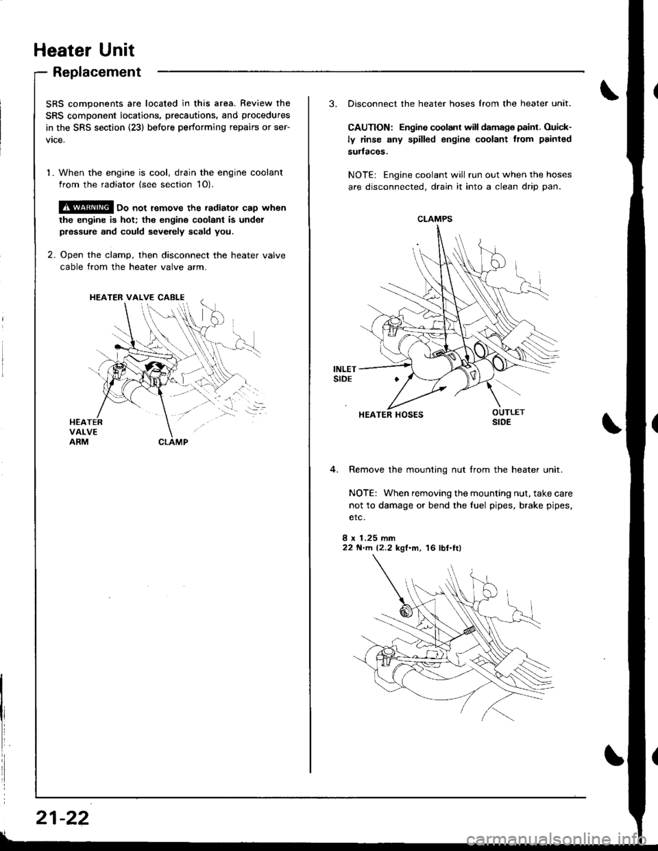
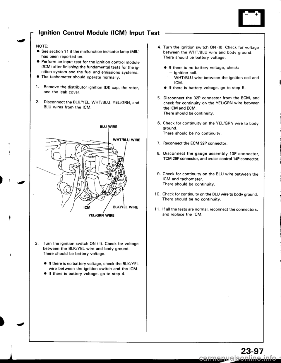
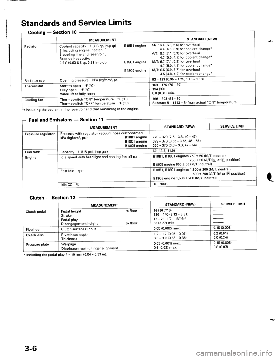
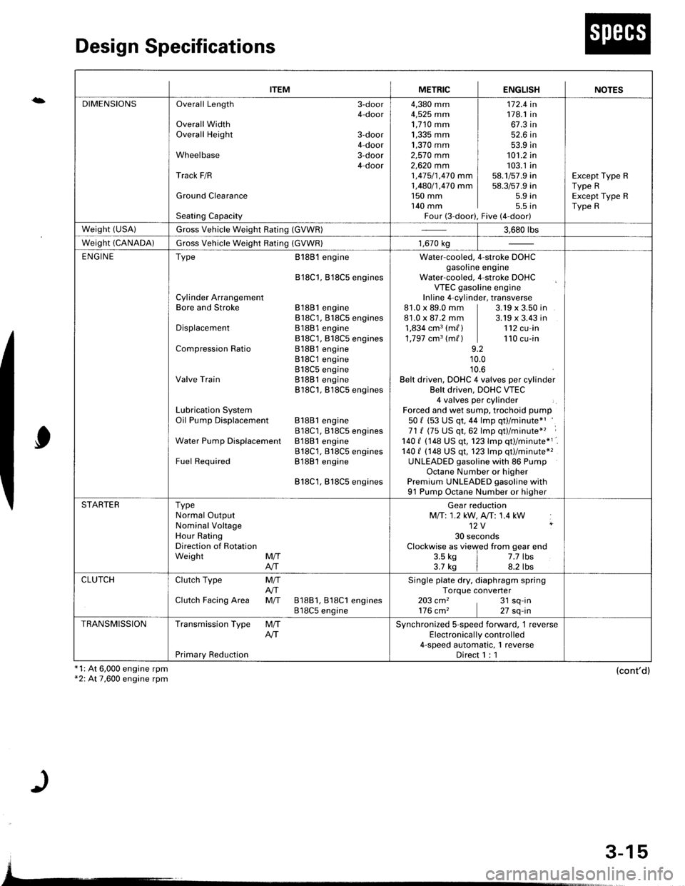
1998 HONDA INTEGRA fuel cap
[x] Cancel search: fuel capPage 351 of 1681

Il
1l
Iil
Emission Control SYstem
EVAPrHREEWAYVALVE
tFi4s6l
fPf 45? I
Evaporative Emission {EVAP) Controls (cont'd)
Possible Csuse
. Fuel fill cap
. Vacuum Connections
. FuelTank
. EVAP Control Canister Vent Shut Valve
. EVAP Control Canister Vent Shut Valve Circuit
. EVAP Purge control Solenoid Valve
. EVAP Purge Control Solenoid Valve Circuit
. EVAP Bypass Solenoid Valve
. EVAP Bypass Solenoid Valve Circuit
o FuelTank Pressure Sensor
. Fuel Tank Pressure Sensor Circuit
. EVAP Control Canister
. Throftle Body
Troubloshooling Flowchart
The scan tool indicates Diagnostic Trouble Code {DTC) P1456: Evaporative Emission (EVAP) control system leak
detected (fuel tank system).
ThescantoolindicatesDiagnosticTroubleCode(DTC)P't457:EvaporativeEmission(EVAP)controlsystemleak
detected (EVAP control canister system)'
VACUUMPUMP/GAUGE,0 - 30 in.Bs
A973X - 041 -
xxxxx
EVAP
CANISTER
EVAPCONTROLCANISTERVENTSHUTVALVE
O-RINGReplace.
ECM CONNECTOR A I32P)
(To page 11-147)
- Tho MIL ha3 bcan t6po.tod
on.- DTC P1,t56 or P1457 i! 3toLd.
Chcck the EVAP contiol canittc.
vont shut valva:1. Disconnect the vacuum hose
Irom the EVAP three way
valve and conned a vacuumpump to the hose
2. Remove the EVAP control
canister vent shut valve {rom
the canister.3. Turn the ignition switch ON lll)
4. Apply vacuum to the hose
Chack tor a lhort in tho wire
lVSv linol:Disconnect the 2P conn€ctor from
the EVAP control canister vent
Does the valve hold vacuum?
Rcp.i. ahoft in thc wir. bctw.cn
th6 EVAP conlrol caniator v.nt
3hut valve snd the ECM lA29).Does the valve hold vacuum?
Check tha EVAP coitlol canittcr
vent 3hut valvo:1. Turn the ignition switch OFF
2. Connect ECM connoctor ter'
minal A29 to bodY ground
whh a iumPer wlre
3. Turn the ignition switch ON (ll).
4. Apply vacuum to the hose.
Baplaca tha EVAP control c!ni!'
td vant 3hul Yalvc.
Does the valve hold vacuum?
38t0tl
1215[6'tat92Au232a
2t27a22
VSV {LT GRN) I JUMPER WIRE
Wire side o{ {emale terminals
11-146
{To page 11'147)
Page 355 of 1681

fIr
Emission Control System
Evaporative Emission Controls (cont'dl
t
ECM CONNECTOR A I32PI
JUMPERWIRE
EVAP BYPASS SOLENOIDVALVE 2P CONNECTOB (C793I
tGl(BLK/WHTIWire side of
femaleterminals
\
ECM CONNECTOR A (32PI
PGl (BLKI
Wire side of lem6l6termrnals
(From page 11-149)
Check iho EVAP bypass solanoid
1. Turn the ignitioo switch OFF.2. Connect ECM connector terminal A28 and body ground witha ,umper wrre.3. Turn the ignition switch ON ill).Chock for an opon in the wire(lGr linell1. Turn the ignition switch OFF.2. Disconnect tho 2P connectorfrom the EVAP bypass sole-noid valve.3. Turn the ignition switch ON (ll).
4. Measure voltage between theEVAP bypass solenoid valve2P connector terminal No. 1and body ground.
Does valve hold vacuum?
Roprir opon in tha wiro batwatanEVAP pu.g6 control solcnoid valvcand thc No. 15 ALTERNATOR SPSENSOR {7.5 Al fu3..
Ch6ck tor an opon in the wile
I2WBS lin6l:'L Tlrrn the ignition switch OFF.2. Reconnect the 2P connectorto the EVAP bypass solenoid
3. Turn the ignition switch ON (ll).
4. Measure voltage between ECMconnector terminals A28 andA10.
Check the following parts lorleakage to atmosphere, andrepsir or roplace if n6ce$try:. fuel fill cap. fuel tank' fuel vapor pipe. EVAP two wsy valve. EVAP bvpess solenoid valve. tuel tank ore33urc son3ot. EVAP control canister. EVAP control canist6r veni3hut valve. EVAP purg. control solenoid
. vacuum hoses and conn6ctions
Rcpair opan in thc wira botwa.nth. EVAP byp!.s sobnoid valvc.nd tfi. ECM lA28l.
3Ia10't1
12l61611t8t9dta22a2a
x272tz3
2WBSIBLUI
wire side ol
femal€terminals
1 1-150
Page 356 of 1681

Evaporative Emission {EVAPI Two Way Valve Tosting
2.
Remove the fuelfill cap.
Remove the vapor line from the EVAP two way
valve, and connect it ro a T-fitting from a vacuum
gauge ano a vacuum pump as shown.
VACUUM/PRESSURE
1.
GAUGE0-a in,Hg
VACUUM PUMP/GAUGE,0 - 30 in.tlgA973X - 041 -
xxxxx
i/NI
t/
il\/
1il|
07JAZ - 001(X)08
3. Apply vacuum slowly and continuously while watch-
ing the gauge. The vacuum should stabilize momen-
tarily at 0.8 - 2.1 kPa (6 - 16 mmHg, 0.2 - 0.6 in.Hg).
lf the vacuum stabilizes {valve opens) below
0.8 kPa (6 mmHg,0.2 in.Hg) or above 2.1 kPa(16'mmHg,0.6 in.Hg), install a new valve and retest.
4. Move the vacuum oumo hose from the vacuum fit-
ting to the pressure fining, and move the vacuum
gauge hose from the vacuum side to the pressure
side as shown.
PRESSUREstoE
Slowly pressurize the vapor line while watching thegauge. The pressure should be stabilize momentarily
above 1.0 kPa (8 mmHg, 0.3 in.Hg).
lf the pressure momentarily stabilizes (valve
opens) above'1.0 kPa (8 mmHg.0.3 in.Hg), the
valve is OK.
lf the pressure stabilizes below 1.0 kPa {8 mmHg,
0.3 in.Hg), install a new valve and retest.
T.FMING
1 1-1 51
Page 1009 of 1681

Heater Unit
Replacement
SRS components are located in this area. Review the
SRS component locatio.s, precautions, and procedures
in the SRS section (23) before performing repairs or ser-
vtce.
1. When the engine is cool, drain the engine coolant
from the radiator (see section 1O).
@ oo not remove the radiator cap when
the engine is hot; the engine coolant is undol
prsssure and could sevdely scald you.
2. Ooen the clamD, then disconnect the heater valve
cable from the heater valve arm.
HEATER VALVE CABI-E
I
i
21-22
3. Disconnect the heater hoses lrom the heater unit.
CAUTION: Engine coolant will damaga paint. Ouick-
ly rinse any spilled engine coolant from painted
sudaces.
NOTE: Engine coolant will run out when the hoses
are disconnected, drain it into a clean drip pan.
4. Remove the mounting nut from the heater unit.
NOTE: When removing the mounting nut, take care
not to damage or bend the fuel pipes, brake pipes,
etc.
8 x 1.25 mm22 N'llt. 12.2 kgl'm, 16 lbl.tl)
CLAMPS
HEATER HOSES
Page 1154 of 1681

lgnition Control Module (lCM) Input Test
NOTE:
a See section 1 1 if the malfunction indicator lamp (MlLl
has been reported on.a Perform an input test for the ignition control module(lCM) after finishing the fundamental tests for the ig-nition system and the fuel and emissions systems.a The tachometer should operate normally.
1. Remove the distributo. ignition (Dl) cap, the rotor,and the leak cover.
2. Disconnect the BLK/YEL, WHT/BLU, YEL/GRN, andBLU wires from the lCM.
3. Turn the ignition switch ON {ll}. Check for voltage
between the BLK/YEL wire and body ground.
There should be battery voltage.
a lf there is no battery voltage, check the BLKiYEL
wire between the ignition switch and the lCM.a It there is battery voltage, go to step 4,
)
I
)
BLU WIRE
YEL/GRN I,\'IRE
4. Turn the ignition switch ON (ll). Check for voltage
between the WHT/BLU wire and body ground.
There should be battery voltage.
a lf there is no battery voltage, check:- ignition coil.- WHT/BLU wire between the ignition coil and
tcM.
a lf there is battery voltage, go to step 5.
5. Disconnect the 32P connector from the ECM, and
check for continuity on the YEUGRN wire between
the ICM and ECM.
There should be continuity.
6. Check for continuity on the YEL/GRN wire to bodygrouno.
There should be no continuity.
7.Reconnect the ECM 32P connector.
Disconnect the gauge assembly 13P connector,
TCM 26P connector, and cruise control l4P connector.
9. Check for continuity on the BLU wire between the
ICM and tachometer.
There should be continuity.
'10. Check for continuity on the BLU wire to body ground.
There should be no continuity.
1 1 . lf all the tests are normal, reconnect the connectors,
and replace the lCM.
23-97
/i
Page 1648 of 1681

Standards and Service Limits
missions - Section 11
* Including the pedal play 1 - 10 mm (0.04 - 0.39 in).
0Gooling - Sectlon
MEASUREMENTSTANDARD (NEW}
RadiatorCoolant capacity / (US qt, lmp qt) 81881 engine
I Including engine, heater, II cooling line and reservoir IReservoir capacity:0.6 f (0.63 US qt, 0.53 lmp qt) 818C1 engine
818C5 engine
M/T: 6.4 (6.8, 5.6) for overhaul4.4 14.6,3.9) for coolant change*
A,/T: 6.7 (7.1, 5.9) for overhaul4.7 $.0,4.1)for coolant change*
M/T: 6.7 (7.1,5.9) for overhaul4.7 (5.0, 4.1) for coolant change*
M/T: 6.5 (6.9, 5.7) for overhaul4.5 (4.8, 4.0) for coolant change*
Radiator capOpening pressure kPa (kgf/cm'�, Psi)93 - 123 (0.95 - 1.25, 13.5 - 17.8)
ThermostatStart to open 'F ("C)
Fully open "F ("C)
Valve lift at fully open
169 - 176 (76 - 80)194 (90)
8.0 (0.31)min.
Cooling fanThermoswitch "ON" temperature "F ('C)
Thermoswitch "OFF" temperature "F ("C)196 - 203 (91 - 95)Subtract 5 - 14 (3 - 8) from actual "ON" temperature
*: Including the coolant in the reservoir and that remaining in the engine
Fuel and E
MEASUREMENTSTANDARD (NEW}SERVICE LIMIT
Pressure regulatorPressure with regulator vacuum hose disconnected
kPa (kgf/cm'�, psi) 81881 engine818C1 engine818C5 engine
270 - 320 (2.8 - 3.3, 40 - 47].
329 - 378 (3.35 - 3.85, 48 - 55)
320 - 370 (3.3 - 3.8, 47 -541
Fuel tankCapacity / (US gal, lmp gal)50 (13.2, 11.0)
Engineldle speed with headlight and cooling fan off rpm81881, 818C1 engines 750 t 50 (M/T: neutral)750 I 50 (A/T: N or E Position)818C5 engine 800 t 50 (M/T: neutral)
Fast idle rpmB1881, 818C1 engines 1,600 t 200 (M/T: neutral)1,600 t 200 (A/T: E or E Position)818C5 engine 1,500 t 200 (M/T: neutral)
ldle CO %0.1 max.
Clutch - Section 'lZ
MEASUREMENTSTANDARD (NEW}SERVICE LIMIT
Clutch pedalPedal height to floor
StrokePedal playDisengagement height to floor
164 (6 7/16)130 - 140 (5.12 - 5.51)12 -21 (12 - 13/16)*83 (3.27) min.
FlywheelClutch surface runoul0.05 (0.002) max,0.15 (0.006)
Clutch discRivet head depthThickness
1.2 - 1.7 (0.05 - 0.07)8.3 - 9.0 (0.33 - 0.35)0.2 (0.01)
6.0 (0.24)
Pressu re plateWarpageDiaphragm spring finger alignmenl
0.03 (0.001) max.0.6 (0.021 max.
0.15 (0.006)
0.8 (0.03)
3-6
Page 1657 of 1681

{b
Design Specifications
x1: At 6,000 engine rpm*2: At 7,600 engine rpm
0
(cont'd)
{
ITEMMETRICENGLISHNOTES
DIMENSIONSOverall Length 3-door4-doorOverall WidthOverall Height 3-door4-doorWheelbase 3-door4-doorTrack F/R
Ground Clearance
Seating Capacity
4,380 mm4,525 mm1,710 mm1,335 mm ]1,370 mm ]2,57O mm2,62O mm 11 ,415/1,470 mm I1,480/1,470 mm I1s0 mm I140 mm IFour (3-door),
172.4 in178.1 in67.3 in52.6 in53.9 in101.2 in103.1 in58.1/57.9 in58.3/57.9 in5.9 in5.5 tnFive (4-door)
Except Type RType RExcept Type RType R
weisht (usA)Gross Vehicle Weight Rating (GVWR)3.680 rbs
Weight (CANADA)Gross Vehicle Weight Rating (GVWR)1,670 kg
ENGINEType
Cylinder ArrangementBore and Stroke
Displacement
Compression Ratio
Valve Train
Lubrication SystemOil Pump Displacement
Water Pump Displacemenl
Fuel Required
8188l engine
818C1, Bl8C5 engines
81881 engine818C1, 818C5 engines81881 engine818C1, B18C5 engines81881 engine818C1 engine818C5 engineB1881 engine818C1, B18C5 engines
81881 engine818C1, B18CS enginesB1881 engine818C1, 818C5 enginesB1881 engine
818C1,818C5 engines
Water-cooled. 4-stroke DOHCgasoline engineWater-cooled, 4-stroke DOHCVTEC gasoline engineInline 4-cylinder, transverse81.0 x 89.0 mm | 3.19 x 3.50 in81.0 x 87.2 mm | 3.19 x 3.43 in1,834 cm3 (m/ ) | 112 cu-in1,797 cm3 (m/ ) | 110 cu-in9.210.010.6Belt driven, DOHC 4 valves per cylinderBelt driven, DOHC VTEC4 valves per cylinderForced and wet sump, trochoid pump50 f (53 US qt, 44 lmp qt)/minute*'71 ( (75 US qt,62 lmp qt)/minute*'� :
140 I 1148 US qt. 123 lmp qtl/minute*1140 t (148 US qt, 123 lmp qt)/minute*2UNLEADED gasoline with 86 PumpOctane Number or higherPremium UNLEADED gasoline with91 Pump Octane Number or higher
STARTERTypeNormal OutputNominal VoltageHour RatingDirection of RotationWeight MffAIT
Gear reductionMfi:1.2 kW, A,/T: 1.4 kW12V ,
30 secondsClockwise as viewed from gear end3.5 ks | 7.7 lbs3.7 kg | 8.2 lbs
CLUTCHClutch Type
Clutch Facing Area
M/TAfiM/T 81881, 818C1 engines818C5 engine
Single plate dry, diaphragm springTorque converter203 cm2 , 31 sq-in176 cm2 | 27 sq-in
TRANSMISSIONTransmission Type
Primary Reduction
M/TAITSynchronized S-speed forward, 1 reverseElectronical ly control led4-speed automatic, 1 reverseDirect 1 : 1
3-15