Page 327 of 1681

rr*
Fuel Supply System
Fuel Filter
Replacement
Do not smoke while working on fuel system. Koop
open flame away from your work atea.
While replacing the fuel filter, be qaretul to keep a
sate distanco between battery terminals and any
tools.
The fuel filter should be replaced whenever the fuel
pressure drops below the specified value I27o - 32O kPa,
2.8 - 3.3 kgf/cm', 40 - 47 psi (B18C'1, B l8C5 enginesi 320- 370 kPa (3.3 - 3.8 kgtcm'�,47 - 54 psi) with the fuel
pressure regulator vacuum hose disconnected and
pinchedl aiter making sure that the tuel pump and the
fuel pressure regulator are OK.
Place a shop towel under and around the fuelfilter.
Relieve fuel pressure {see page 11-1'18}.
Support the fuel filter with a wrench, as shown,
then remove the 12 mm banjo bolt and the tuel feed
pipe lrom the fuelfilter.
Remove the fuel filter clamp and fuel filter.
lnstall the new fuel filter in the reverse order of
removal, and note these items:
. When assembling, use new washers as shown.
. Clean the tlared joint of high pressure hoses
thoroughly before reconnecting them.
\,,
9.8 N.m {1.0 kgf.m,7.2 tbf.frl
WRENCH
12 mm BANJO BOLT33 N.m 13.4 kgf.m. 25 lbl.ftl
37 N.m (3.8 kgf.m,27 lbf.ft)
Page 329 of 1681

1L
i
!i
!
{
Fuel Supply System
PGM-Fl Main Relay
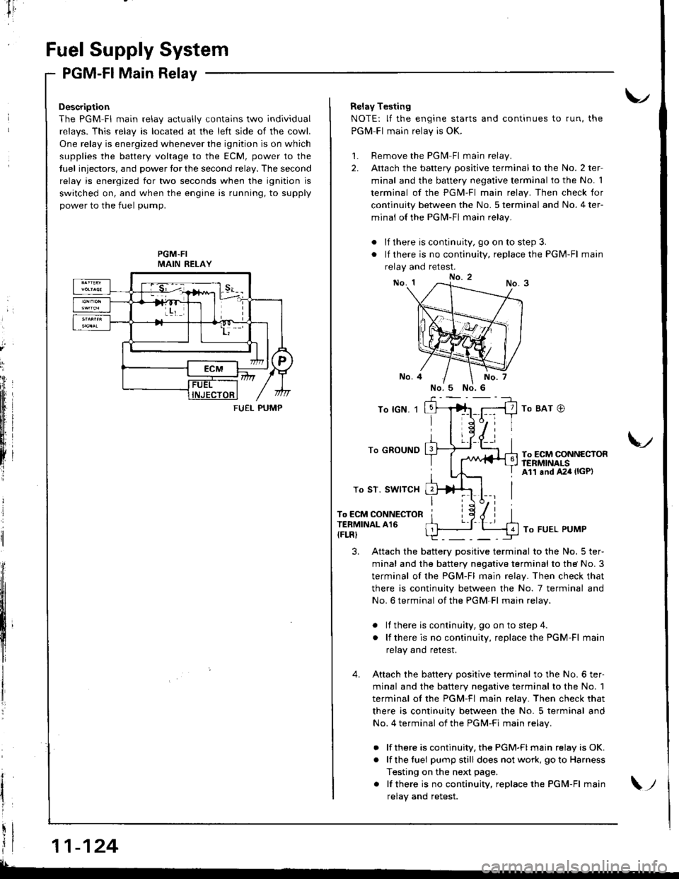
Description
The PGM Fl main relav actuallv contains two individual
relavs. This relav is located at the left side of the cowl.
One relay is energized whenever the ignition is on which
supplies the battery voltage to the ECM, power to the
tuel injectors, and power tor the second relay. The second
relay is energized for two seconds when the ignition is
switched on, and when the engine is running, to supply
power to the fuel pump.
PGM-FIMAIN RELAY
11-124
FUEI- PUMP
Relay Testing
NOTE: lf the engine starts and continues to run, the
PGM-Fl main relay is OK.
1. Remove the PGlvl Fl main relay.
2. Attach the battery positive terminal to the No. 2 ter-
minal and the battery negative terminal to the No. 1
terminal of the PGM-Fl main relay. Then check for
continuity between the No. 5 terminal and No. 4 ter-
minal of the PGN4-Fl main relay.
. lf there is continuity, go on to step 3.
. lf there is no continuity, replace the PGM-Fl main
relay and retest.
To lGN. 1
To GROUND
To ST. SWITCH
To ECM CONNECTORTERMINAL A16
{FLRI
To BAT @
To ECM CONNECTORftNMNALSAll and A24 (lGP)
V
To FUEL PUMP
3. Attach the battery positive terminal to the No. 5 ter-
minal and the battery negative terminal to the No. 3
terminal of the PGM-Fl main relay. Then check that
there is continuity between the No. 7 terminal and
No. 6 terminal of the PGM-Fl main relav.
. lf there is continuity, goon tostep4.
. lf thereis nocontinuity, replacethe PGM-Fl main
relay and retest.
4. Attach the batterv oositive terminal to the No. 6 ter-
minal and the battery negative terminal to the No. 1
terminal ol the PGM-Fl main relay. Then check that
there is continuity between the No. 5 terminal and
No. 4 terminal of the PGM-Fi main relav.
. lf there is continuity, the PGM-FI main relay is OK.
. lf the fuei pumpstill does not work, goto Harness
Testing on the next page.
. lf thereis nocontinuity, replacethe PGM-Fl main
relav and retest.\;
Page 330 of 1681

I
tr,
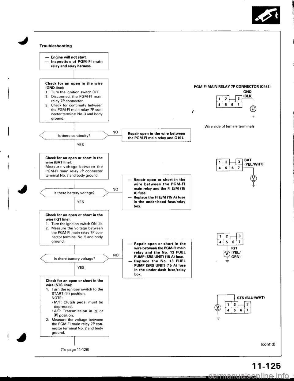
- Engine will not start.- Inspection of PGM-FI mainrelay and relay harne$.
Check lor an open in the ware{GND line}l1. Turn the ignition switch OFF.2. Disconnect the PGM Fl mainrelay 7P connector.3. Check for continuity betweenthe PGM'FI main relay 7P connector terminal No. 3 and bodyground,
Repair open in the wire betweenthe PGM-Fl main relay and G101.
Check for an open or shon in thewire {BAT line)rMeasure voltage between thePGM-Fl main relay 7P connectorterminal No.7 and body ground.- Fepaii open or short in thewire between the PGM-FImain rel6y and the Fl E/M 115A) tuse.- Replace th€ Fl E/M {15 A)fusein the under-hood tuse/relay
ls there battery vohage?
Check foi an open or shori in thewire (lG1 line):1. Turn the ignition switch ON (ll).
2, Measure the voltage betweenthe PGM Fl main relay 7P con-nector terminal No. 5 and bodyground,R€pair open or short in thewire betwo€n the PIGM-FI mainrelav and the No. 13 FUELPUMP ISRS UNIT) (15 Altuse.ReDlace the No. 13 FUELPUMP ISRS UNID (15 Al fusein the under-dash tuse/relayoox,
Check for an open or short in thewire {STS linel:1. Turn the ignition switch to theSTART { lll) position.NOTE:. M/T: Clutch pedal must beoepresseo.. A/T: Transmission in ld or
E position.2. Measure the voltage betweenthe PGM-FI main relay 7P con-nector terminal No. 2 and bodyground,
Troubleshooting
'l RELAY 7P CONNECTOR
GND
t .--.-l T;-l IBLK)L' 'r I" T----
lr s o rl A
+
Wire side o{ female termanals
8AT(YEL/WHT)
STS {BLU/WHTI
(cont'd)
(To page11- t 26)
11-125
Page 333 of 1681
r
Intake Air System
System DescriptioSystem uescnpllon
The system supplies air for all engine needs. lt consists of the intake air pipe. Air Cleaner (ACL), intake air duct, Throttle
Body (TB), ldle Air Control (lAC) Valve, fast idle thermo valve (A,/T model only), and intake manifold.
A resonator in the intake air pipe provides additional silencing as air is drawn into the system.
B18Cl engine lB18Bl, B18C5 enginos does not havs the IAB systeml:
IABCONTROLsollNolDVALVE
VARIOUSSENSORS
IABCONTROLDIAPHRAGM
IiITAKEAIR PIPE
INTAKE MANIFOLDINTA|(EAIRDUCT
RESONATOR
Page 335 of 1681

l-
Intake Air System
LOCKNUT
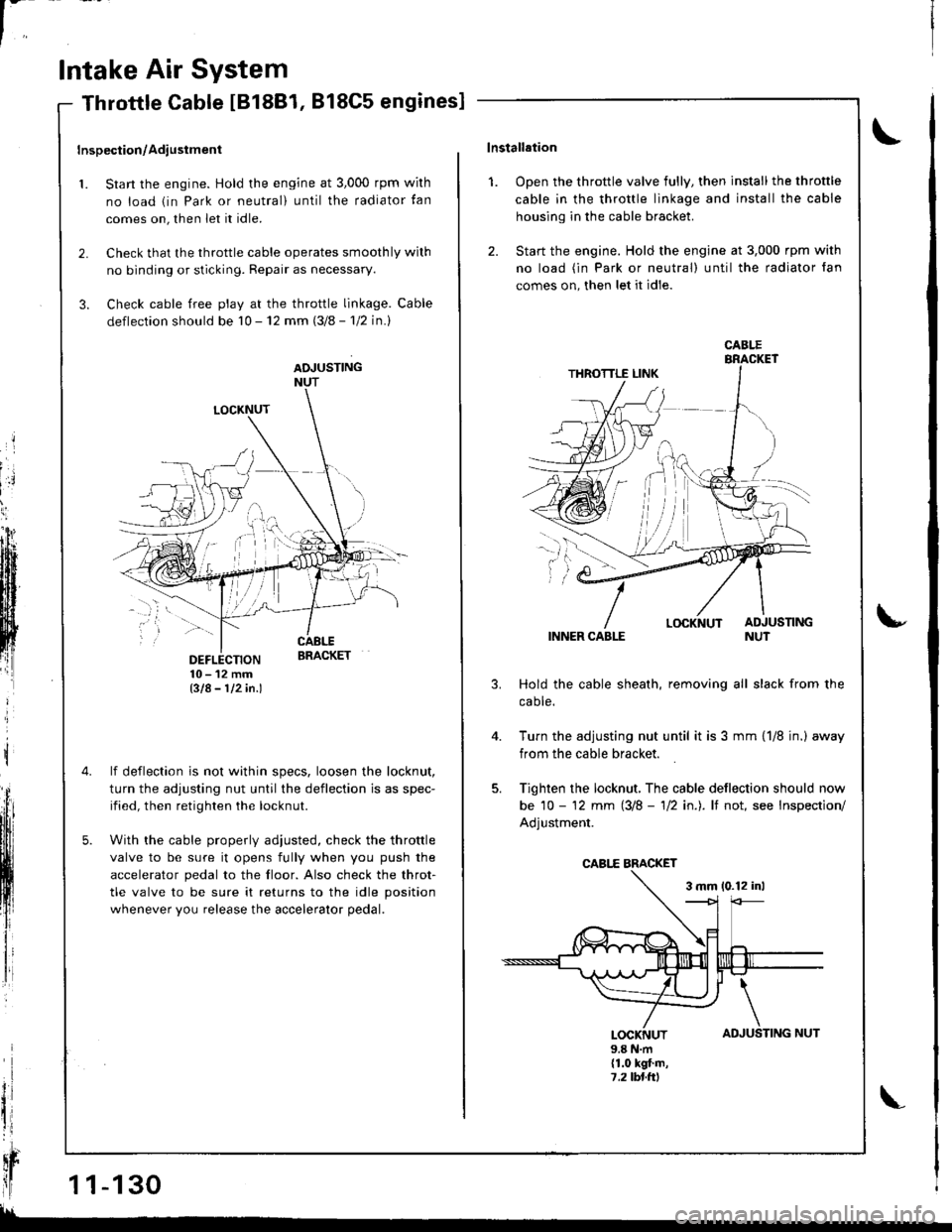
DEFLECTION10-12mmBIA- 112in.l
lf deflection is not within specs, loosen the locknut,
turn the adjusting nut until the deflection is as spec-
ified, then retighten the locknut.
With the cable properly adiusted, check the throttle
valve to be sure it opens fully when you push the
accelerator pedal to the floor. Also check the throt-
tle valve to be sure it returns to the idle position
whenever you release the accelerator pedal.
Throttle Cable IB18B1, 818C5 engines]
Inspection/Adiustment
1. Start the engine. Hold the engine at 3,000 rpm wirh
no load (in Park or neutral) until the radiator tan
comes on, then let it idle.
2. Check that the throttle cable operates smoothly wilh
no binding or sticking. Repair as necessary.
3. Check cable free play at the throttle linkage. Cable
deflection should be 10 - 12 mm (3/8 - 'l12 in.l
ADJUSTINGNUT
t
il
qr
ll1 1-130
!!
TING NUT
\lnstallation
1. Open the throttle valve fully, then install the throttle
cable in the throttle linkage and install the cable
housing in the cable bracket.
2. Start the engine. Hold the engine at 3,000 rpm with
no load (in Park or neutral) until the radiator fan
comes on, then let it idle.
INNER CABLE
Hold the cable sheath, removing all slack from the
caote.
Turn the adjusting nut until it is 3 mm {1/8 jn.) away
from the cable bracket.
Tighten the locknut, The cable deflection should now
be 10 - '12 mm (3/8 - 'll2 in.). lf not, see Inspection/
Adjustment.
3 mm 10.12 inl
u
4.
AD
\
JUSLOCKNUT9.8 N.m(1.0 kgt.m,7,2lbl.ttl
CABI.E
CABI,E BMCKET
Page 336 of 1681

't.
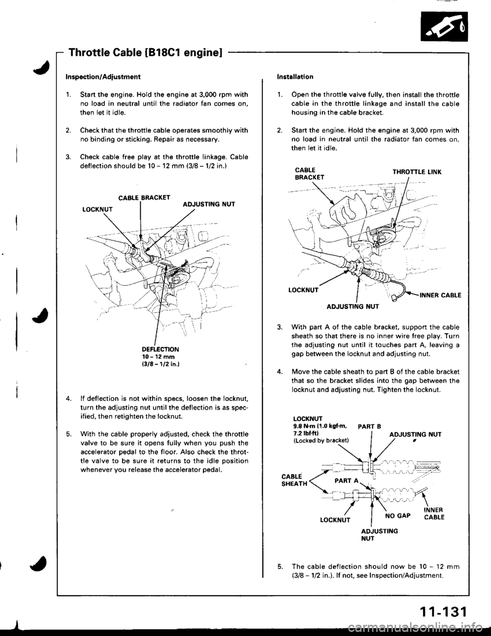
Inspsction/Adiustmsnt
Stan the engine. Hold the engine at 3,000 rpm with
no load in neutral until the radiator fan comes on,
then let it idle.
Check that the throttle cable operates smoothly with
no binding or sticking. Repair as necessary.
Check cable free play at the throttle linkage. Cable
deflection should be 10 - 12 mm (3/8 - 1/2 in.)
DEFTECTION10- 12 mmBIA-112in.l
lf deflection is not within specs, loosen the iocknut.
turn the adjusting nut until the deflection is as spec-
ified, then retighten the locknut.
With the cable properly adjusted, check the throttle
valve to be sure it opens fully when you push the
accelerator pedal to the floor. Also check the throt-
tle valve to be sure it returns to the idle position
whenever you release the accelerator pedal.
CABLE BBACKET
lnstallation
Open the throttle valve fully, then install the throttle
cable in the throttle linkage and install the cable
housing in the cable bracket.
Stan the engine. Hold the engine at 3,000 rpm with
no load in neutral until the radiator fan comes on,
then let it idle.
l.
3.
5.
CABLEBRACKETTHROTTLE LINK
ADJUSTING NUT
With part A of the cable bracket. support the cable
sheath so that there is no inner wire tree plav. Turn
the adjusting nut until it touches part A, leaving a
gap between the locknut and adjusting nut.
Move the cable sheath to oart B of the cable bracket
that so the bracket slides into the gap between the
locknut and adjusting nut. Tighten the locknut.
LOCKNUT9.8 N.m 11.0 kgf.m, PART 87.2lbf.frl(Lockod by bracketl
CABLESHEATH
NO GAPINNERCABLE
ADJUSTINGNUT
The cable deflection should now be 10 - 12 mm(318 - 112 in.l. lf not. see Inspection/Adjustment.
ADJUSTING NUT
1 1-131
Page 337 of 1681

In
Intake Air System
Throttle Body
$;
Description
The throttle body is of the single barrel side-draft type.
The lower portion of the throttle valve is heated by
engine coolant from the cylinder head. The idle adjusting
screw which increases/decreases bypass air is located on
the top ot the thronle body.
IDLE ADJUSTINGSCREW
THROTTLESTOP SCREW(Non-adjustable)
FAST IDLE
| | .o clearance. THRoTTLE SToP scREw
{ | | _ .lDonotadiust)
| | y:::::::T,"9":::.'"Tl::f ,::i1::"1" fllyll-'n"
VALVE {A/T model onlv}
Inspection
1. Start the engine. Hold the engine at 3,000 rpm with
no load {in Park or neutral) until the radiator fan
comes on, then let it idle.
2. Stop the engine, and check that the throttle cable
operates smoothly without binding or sticking.
. lf the throttle body pon is clogged, clean it with
carburetor cleaner.
. lf there are any abnormalities in the above steps,
check for:
Excessive wear or play in the throttle valve shaft.- Sticky or binding throttle lever at full close posi-
tion.- Clearance between throttle stop screw and throt-
tle lever at fullclose position.
81881, Bl8Cl engines:
There should beno clearance.
818C5 engine:THROTTLE LINK
There should be
throttle valve shaft or if the shaft is binding or sticking.
glL-
Page 339 of 1681
'{[
'll
I
l'
)l
t,t
H
Ili
Intake Air System
Intake Air Bypass (lAB) Control System [818C1 enginel
Descriplion
Two air intake oaths are erovided in the intake manifold to allow the selection of the intake path most favofable for a given
engine speed.
Satjsfactory power performance is achieved by closing and opening the intake air bypass (lAB) control valves. High torque
at low RpM is acheived when the valves are closed, whereas high power at high RPM is achieved by when the valves are
opened.
IAB CONTROLVALVES
ECM
illf1l
i 11-134
--_
CHECI( VALVE