Page 1513 of 1681
Back-up Lights
-.I UNDER.DASH
I I ruSr rs I FUSETRELAY
| ! 1;" ," uo"'. I F"?T" *
I i- |L-J-----J'o Y "c,fl13.,YEL I YEL s€e powsr
a- Distribution,
- Hatchback
Automatic Transmission
page 10-4.
l\4anual Transmission
*'l
A/T GEARPOSITIONswtTcH
.=L=r-.
!"1"''1,!
.frl_.j
Io
BLKYeLr
I.II-II'
"Tt
"*,
erx I eaoro roa
arrrr-<
"'i
U "ro'':;^::;:"
"""1:i*#J;;;"
r# aacr-upI 1 | LrcHT swrrcH
I t _ | l]"^#1,;:. tra.lsm,ss,on
o"n,".*F "noto t'
","'"J, fi ";o'8"
""",J; fi F;%,,
"""JIft 9,:%,,
""-".t- [
t*'
fi f,f.l,l" "onn"",o.,
*" *_
I ilil,?:lli 0,"""",
o"n".*!ffi;-'l
,lF;,;,,,
:l::. ,fffi:,*
canre.*l i$itdq o"n".*f
@ l.:{;*-," ""g#'"'c'o*
@
g.[H,,.
rt
IA
F
I
See GroundDistribution,page 14-7.
G503
"Tt
"u,.
au I Puoto 'oe
Frrrrra
110
BLK
Page 1514 of 1681
- Sedan
Automatic Transmission
:ibi"lf:li::",""
I
I
I
I
.$t=t
i " j'*'-1,
| " &---? ar
",::i'*
'
A/T GEARPOStTtONSWITCH
3 .i c422
n"n,".^ |
"'oto'u
* tf-l:" "o"""",o,,
o"n,".^
! il?,l?lli o'""""'
o"n ur* | o"n ".* [
o"*"*
|
t *"";%,,, u l"uro ...^.lln*,,,cn,r ar-x .ff
-"" " '"
Hl+irT" GRN 8tx )t
@i[r"t"
coNNtcroR
Qphft,"
".*f af,,. - see crou!.c
"*!#
a-< Distribution, _.._ I"ri:3rr:''*sr ri;;;'l
^:"Y9;%,,, ".^| """'
s€ecround
:---< 3lflit8:'
G503PHO|O 102
'i[,rr*,'
i,!,.1t;"%""
o"",".?frFH''Ffi elcr.up
| | r-rcxr swncx
I t_rl fi,ffi$#1, transm'ssion
o"n,".*F "'oto oo
*",Jf, F;0,3,"
""",Jlt "";t%,.
""""'Jf "";%"
110-1
Page 1558 of 1681

lnterlock System
- How the Circuit Works
Key Interlock
Battery voltage is supplied at all times through f use
33 to the key interlock switch. When the key is in
the ignition, battery voltage is supplied to the key
intedock solenoid and the key interlock circuit in the
interlock control unit. When the A/T gear position
switch is in PABK, ground is provided to the key
interlock circuit. This removes ground from the
interlock solenoid, the solenoid is deenergized, and
the key can be removed from the ignition.
Shift Position Interlock
Battery voltage is supplied at all times lrom fuse 52
to the brake switch. With the ignition in ON (ll) or
START (lll), battery voltage is supplied through luse
25 to the shift lock solenoid. When you push the
brake pedal, battery voltage is applied through the
GRN/VVHT wire to the transmission ('98-�99 models)
or powertrain ('00 model) control module (TCM or
PCM). lf, at the same time, you do not push the
accelerator pedal, a low voltage signal is sent
through the RED/BLK wire to the TCM or PCM. The
TCM or PCM then applies voltage through the
WHT/RED wire to the shift lock circuit in the
interlock control unit. lf the A,/T gear position switch
is in the PARK position, the shift lock circuit
provides ground to the shift lock solenoid. The
solenoid is then energized, and the shift lever can
be moved from the PARK Dosition.
Refer to the Service Manual (Section 23, Electrical)
for specific tests or troubleshooting procedures.
138-2
Page 1569 of 1681
Component Location
b-
13. Right Front Corner of Engine Compartment16. Right Side of Engine (GS-R Shown, Others Similar)
14. Top Front of Manual Transmission17. Right Side of Engine (All Except GS-R)
15, Top Front ot Automatic Transmission18. Right Side of Engine (GS-R)
l201-2
Page 1571 of 1681
25. Top Rear of Automatic Transmission ('98-'99 Mod.)
Component Location
\
28. Right Side of Engine
26. Too Rear ot Transmission29. Center Rear of Engine (Type-R)
27 . Lower Right Side of Engine Compartment30. Center Rear of Engine (All Except GS-R)
201-4
Page 1573 of 1681
37. Left Side of Engine Compartment
Component Location
!
42. Underside of Car. Bight Bear ot Transmission
40. Underside of Car. Front of Manual Transmission
38. Behind Left Side of Air Scooo41. Underside of Car, Front of Transmission ('98-'99)
39. Underside of Car, Left Front Corner of Engine
201-6
Page 1596 of 1681

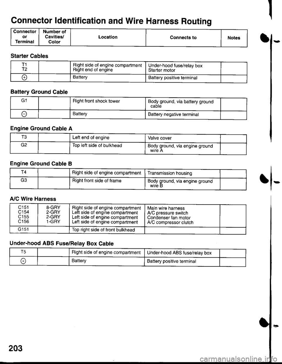
Connector ldentification and Wire Harness Routing
Connector
OT
Terminal
Number of
Cavities/
Color
LocationConnecls toNotesI
fl-
Starter Cables
T1
T2Right side of engine compartmentRight end of engineUnder-hood fuse/relav boxStarter motor
oBatteryBattery positive terminal
Battery Ground Cable
lRight front shock towerBodyground, via battery ground
ABatteryBattery negative terminal
Engine Ground Cable A
T3Left end of engineValve cover
Top left side ol bulkheadBody ground, via engine ground
Engine Ground Cable B
T4Right side of engine compartmentTransmission housing
Right front side of trameBody ground, via engine ground
wrre b
A,/C Wire Harness
Under-hood ABS Fuse/Relay Box Cable
203
c151
c'154utSc
u tco
8-GRY
2-GRY
2-GRY
1-GRY
Right side ol engine compartmentLeft side of engine compartmentLeft srde of engine compartmentLeft side of engine compartment
Main wire harness
A'lC pressure switch
Condenser tan motorA,/C compressor clutch
lrlclTop right side ot front bulkhead
T5Right side of engine compartmentUnderhood ABS fuse/relav box
\,BatteryBattery positive terminal
Page 1598 of 1681

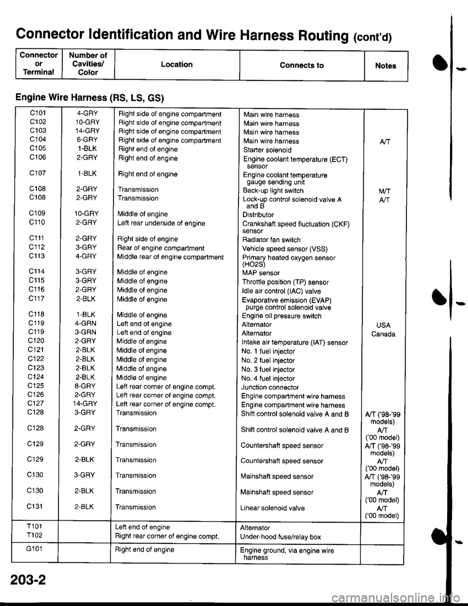
Connector ldentification and Wire Harness Routing (cont,d)
Connector
or
Terminal
Number ot
Cavities/
Color
LocationConnects toNotes
Engine Wire Harness (RS, LS, GS)
c101
c102
c103
c104
c105
c106
c 107
c108
c108
c'1 09
c110
c111
cl12
c113
c'114
c115
c116
c117
c118
c119
c1 19
c120
c121
c122
c123
c124
cl25
cl26
c127
Ql28
c128
c129
c 129
c130
c'l30
c131
4.GRY
1O.GRY
14-GRY
6-GRY
1.BLK
2-GRY
,1-BLK
2-GRY
2.GRY
1O-GRY
2-GRY
2-GRY
3-GRY
4-GRY
3-GRY
3-GRY
2-GRY
2.BLK
.1-BLK
4-GRN
3-GRN
2-GRY
2.BLK
2-BLK
2-BLK
2.BLK
8-GRY
2-GRY
14-GRY
3-GRY
2.GRY
2.GRY
2-BLK
3-GRY
2-BLK
2-BLK
Right side of engine compartment
Right side of engine compartment
Right side ot engine compartment
Right side of engine compartment
Right end of engine
Right end of engine
Right end of engine
Transmission
Transmission
lvliddle ol engine
Lett rear underside of engine
Right side ol engine
Rear of engine compartment
Middle rear ol engine compartment
Middle ol engine
Middle of engine
Middle ol engine
l\4iddle of engine
Middle of engine
Left end ot engine
Lett end of engine
Middle of engine
N,liddle ol engine
Middle of engine
Middle of engine
Middle of engine
Left rear corner of engine compt.
Lelt rear corner of engine compt.
Left rear corner of engine compt.
Transmission
Transmission
Transmission
Transmission
Transmission
Transmission
Transmission
Main wire harness
Main wire harness
Main wire harness
Main wire harness
Starter solenoid
Engine coolant temperature (ECT)sensor
Engine coolant temperaturegauge sending unit
Back-up light switch
Lock-up control solenoid valve Aand B
Distributor
Crankshaft speed fluctuation (CKF)sensor
Radiator fan switch
Vehicle speed sensor (VSS)
Primary heated oxvoen sensor(H02s)
MAP sensor
Throttle position (TP) sensor
ldle air control (lAC) valve
Evaporative emission (EVAP)purge control solenoid valve
Engine oil pressure switch
Alternator
Alternator
Intake air temperature (lAT) sensor
No. I fuel injector
No. 2 fuel injector
No. 3 tuel injector
No. 4 fuel injector
Junction connector
Engine compartment wire harness
Engine compartment wire harness
Shitt control solenoid valve A and B
Shift control solenoid valve A and B
Countershaft speed sensor
Countershatt speed sensor
lvtainshatt speed sensor
Mainshaft speed sensor
Linear solenoid valve
NT
[/VT
A"/T
USA
Canada
A/T (98199models)
AIT('00 model)
A,/T ('98-'�99models)
('00 model)
A,/T f98-'99models)
Atf('00 model)
AN('00 model)
T101
T102
Left end of engine
Right rear corner of engine compt.
Alternator
Under-hood fuse/relay box
G'101Right end ot engineEngine ground, via engine wirenarness
o
I
203-2