Page 1200 of 1681
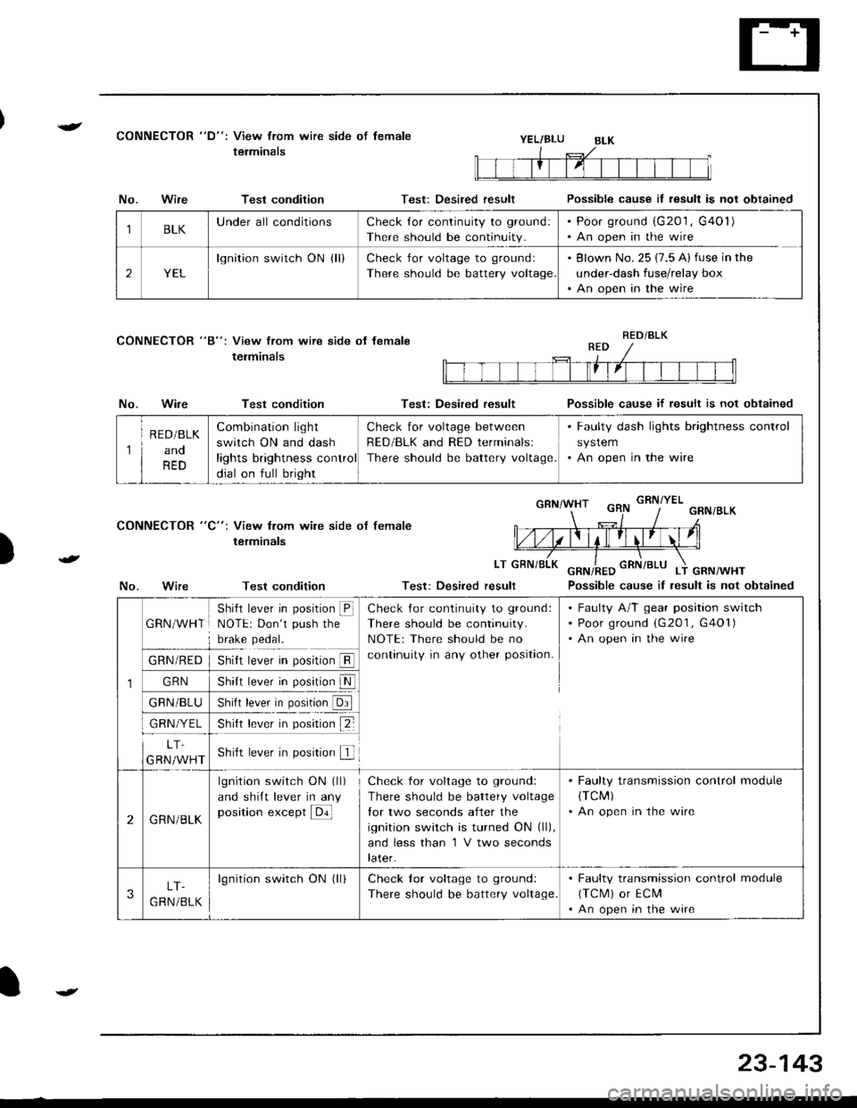
{CONNECTOR "D": View from wire side of lemale
terminalsYEL/BLU
CONNECTOR "8": View from wire side ot female
terminals
No.Wire
No.Wire
Test condition
Test condition
Test condition
Test: Desired result
Test: Desired result
Possible cause il result is not obtained
Possible cause if result is not obtained
Possible cause iI lesult is not obtained
)
CONNECTOR "C": View from wile side ot female
terminals
LT
No.Test: Desired result
1BLKUnderall conditionsCheck {or continuity to ground:
There should be continuity.
Poor ground (G201 , G401)
An open in the wire
2YEL
lgnition switch ON (ll)Check for voltage to groundl
There should be battery voltage
Blown No. 25 (7.5 A) fuse in the
under-dash fuse/relay box
An open in the wire
RED/BLK
1
R E D/BLK
ano
RED
Combination light
switch ON and dash
lights brightness control
dial on full bright
Check for voltage between
RED/BLK and RED terminalsl
There should be battery voltage.
. Faulty dash lights brightness control
system. An open in the wire
1
GRN/WHT
Shifl lever in position @NOTE: Don't push the
brake pedal.
Check {or continuity to ground:
There should be continuity.
NOTE: There should be no
continuity in any other position.
Faulty A/T gear position switch
Poor ground (G201 , G401)
An open in the wire
GRN/RED
GRN
GRN/BLU
GRN/YEL
5nrrI rever In pos[ron ll
shl, b*|' il. p"1,!lN
)nrn rever In posrron url
snt r""-. r p*;ir" tZ-
LT.
GRN/WHTShift lever in position f
2GRN/BLK
lgnition switch ON (ll)
and shift lever in any
position except E
Check for voltage to ground:
There should be battery voltage
lor two seconds after the
ignition switch is turned ON (ll),
and less than 'l V two seconds
later.
. Faulty transmission control module(TCM)
. An open in the wire
3LT-
G RN /BLK
lgnition switch ON (ll)Check lor voltage to ground:
There should be battery voltage.
. Faulty transmission control module
(TCM) or ECM'An open in the wire
23-143
Page 1203 of 1681
Interlock System
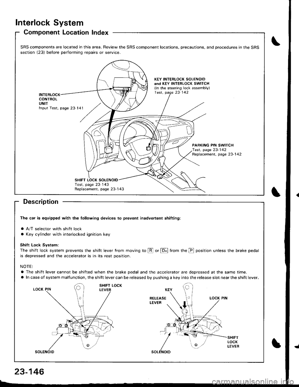
Component Location Index
Description
The car is equipped with the lollowing devices to plevent inadvertent shifiing:
a A/T selector with shift lock
a Key cylinder with interlocked ignition key
Shift Lock Svstem:
The shift lock system prevents the shilt lever trom moving to @ or [6ol from the p position unless the brake pedal
is depressed and the accelerator is in its rest position.
NOTE:
a The shift lever cannot be shifted when the brake pedal and the accelerator are depressed at the same time.
a In case of system malfunction, the shift lever can be released by pushing a key into the release slot near the shift lever.
SRS components are located in this area. Review the SRS component locations, precautions, and procedures in the SRS
section (23) belore performing repairs or service.
KEY INTERLOCK SOLENOIDand KEY INTERLOCK swlTCH
{ln the steering lock assembly}
INTERLOCKCONTROLUNIT
PARKING PIN SWITCHTest, page 23-142Replacement, page 23-1 42
Replacement, page 23-143
SHIFT LOCK SOL€NOIDTest, page 23 143
23-146
Page 1205 of 1681
lnterlock System
Circuit Diagram
NOTE: Different wires with the same color have been given a number suflix to distinguish them (for example,cRNA/VHT I and cRNMHT '� are not the same).
WHT/ BLK .-- WHI
cnrruvgr'
+. BRAKE LIGNTS.CSUISE CONTROLUNIT. ABS COIITROL UNIT' ECM
INTEBLOCKCONTROLUNIT
A]'IGEARPOStTIONINOICATOR
v
t,
UNDER-HOOO FUSEi RELAY BOX
N0.41 (100A) N0.42 (404)
YEUBLUcnrivrr '
WHT/BLU
KEYINTERLOCKswtTcH
THBOTTLEPosrT|0N (TP)SENSOR
f7
IRED/BLK
(Cjl :in posiron E t
23-14A
Page 1206 of 1681
){r/
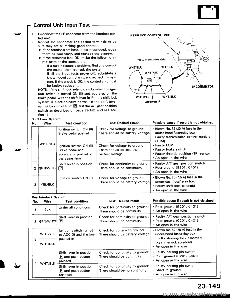
Control Unit Input Test
1. Disconnect the 8P connector from the interlock con-
trol unit.
2. lnspect the connector and socket terminals to be
sure they are all making good contact.
a It the terminals are bent, loose or corroded, repair
them as necessary, and recheck the system.
a lf the terminals look OK, make the following in-
put tests at the connector.- lf a test indicates a problem, tind and correct
the cause, then recheck the system.- lf all the input tests prove OK, substitute a
known-good control unit, and recheck the sys-
tem. lf the check is OK, the control unit must
be faulty; replace it.
NOTE: lf the shift lock solenoid clicks when the igni-
tion switch is turned ON (ll) and you step on the
brske Dedal (with the shift lever in E). the shift lock
system is electronically normal; if the shift lever
cannot be shifted from fl, test the 46 gear position
switch as described on page 23-142, and see sec-
tion 14.
Shift Lock System:
No. Wire Test condition
No. WireTest condition
Test: Desired resultPossible causs it result is not obtained
Test: Dcsired lesultPossible cause it result is not obtainsd
INTERLOCK CONTROL UNIT
GRN/wHT2
1WHT/RED
lgnition switch ON (ll)
Brake pedal pushed
Check for voltage to ground:
There should be battery voltage
Blown No. 52 {20 A) fuse in the
under-hood fuse/relaY box
Faulty transmission control module
(TCM)
Faulty ECM
Faulty brake switch
Faulty throttle position (TP) sensor
An open in the wire
lgnition switch ON (ll)
Brake pedal and
accelerator pushed at
the same me
Check for voltage to ground:
There should be less than
battery voltage.
tGRN/WHT'
Shift lever in position
E
Check tor continuity to ground:
There should be continuity.
Faulty A/T gear position switch
Poor ground {G20'1 , G401)
An open in the wire
3YEL/BLK
lgnition switch ON (ll)Check for voltage to ground:
There should be battery voltage
Blown No. 25 (7.5 A) fuse in the
under-dash fuse/relay box
Faulty shift lock solenoid
An open in the wire
Key Int€rlock Systcm:
BLKUnder all conditionsCheck lor continuity to ground:
There should be continuitY.
. Poor ground (G201, G401). An open in the wire
GRNiWHT'
Shift lever in position
E
Check for continuity to ground:
There should be continuity.
Faulty A/T gear position switch
Poor ground {G2O1, G401 }
An open in the wire
3
WHT/YELlgnition switch turned
to ACC (l) and the key
pushed in
Check tor voltage to ground:
There should be battery voltage.
Blown No. 52 (20 A) fuse in the
under-hood fuse/relaY box
Faulty steering lock assemblY
(key interlock solenoidl
An open in the wireWHT/BLU
4WHT/BLK
Shift lever in position
E and push button
pressed
Check for continuity to ground:
There should be continuity.
Faulty pafking pin switch
Poor ground (G2O1, G4O 1)
An open in the wire
Shift lever in position
E and push button
reteaseo
Check for continuity to ground:
There should be no continuity.
Faulty parking pin switch
Short to ground
An open in the wire
I'
23-149
Page 1209 of 1681
Integrated Control Unit
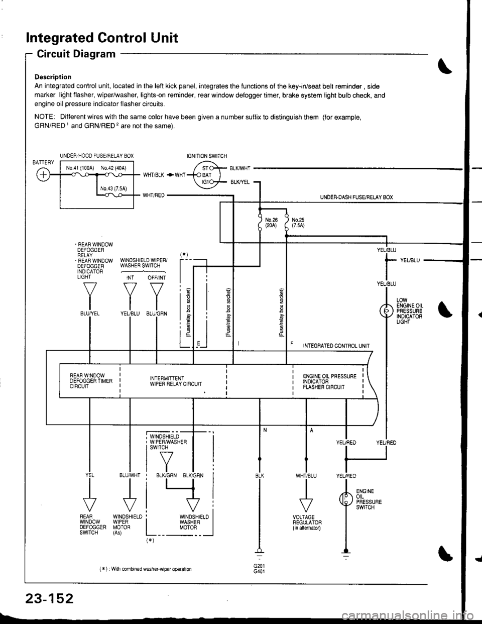
Circuit Diagram
Description
An integrated control unit, located in lhe left kick panel, integrates the lunctions of the key-in/seat belt r€minder , side
marker light llasher, wiper/washer, lights-on reminder, rear window delogger timer, brake system light bulb check, and
engine oil pressure indicator flasher circuits.
NOTE: Different wires with the same color have been given a nu mber suflix to distinguish them (for example,
GRN/RED I and GRN/RED'� are not the same).
REAR WINDOWDEFOGGERRELAYREAF WINDOWDEFOGGENIND CATORL GHT
f-7
IIBLU/YEL
WHT/ BLK
WHT/ REO
+WHT
WNDSHIELDWIPERiWASHER SWITCH
INT OFF/INT
f7 f7
tltlYEUBLU 8LU/GRN
BLUMHT
J
wtN0sHr€10WIPERMOTOR
UNDER.DASH FUSARETAY BOX
F rmecnlleo counoL ultr
YEUBLU
rYEUBLU
YEUREO YEUREO
tl
IYEURED
LOWENGINEOIIPRESSUREINOICATOBLIGHT
; WINDSHIELD' WIPERMASHERI swlTcH
tf7IVtlYEL
J
FEARwtN00wOEFOGGERSWITCH
WHTIBLU
J
VOTTAGEREGULATOR(ln allernatol)
BLK
G441
ENGINEolLPRESSUREswrTcH
UNDER-NOOO FUSE/RELAY BOX
1.6
:6
t;t-L
i
"'i'- 'i*-
|
I Il
I vi: WINDSHIELO II WASHEB I
L__ "oto: _ __l(*)
n
s
s
,]
23-152
(*) :Wilh combined washer-wiper operalion
Page 1214 of 1681
M
lgnition switch at
START iIII)
Check for voltage to ground:
There should be battery voltage.
Blown No.31 (7.5 A) fuse in the
under-dash fuse/relay box
Faulty clutch interlock switch or
starter cut relay (M/T)
Faulty neutral position switch (A/T)
An open in the wire
2D
lgnition switch ON {ll).
brake fluid reservoir
full, and parking brake
tever oown
Connect to ground: Brake
system light should come on.
. Blown brake system light. An open in the wire
Bulb Check System (brake system light)
No. Terminal Test conditionTost: Desiled resultPossiblo cause if lesult is not obtained
)
)
23-157
Page 1222 of 1681
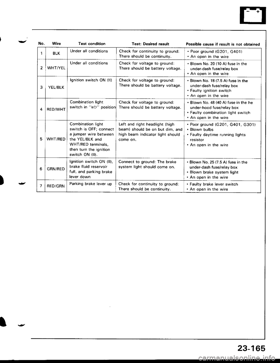
Tsst conditionTest: Desiled resultPossible cause it result is not obtained
)
BLKUnder all conditionsCheck for continuity to ground:
There should be continuity.
. Poor ground (G201 , G40l ). An open in the wire
2WHT/YEL
Under all conditionsCheck for voltage to ground:
There should be battery voltage.
. Blown No. 20 (10 A) fus€ in the
under-dash fuse/relay box. An open in the wire
YEL/BLK
lgnition switch ON (ll)Check for voltage to ground:
There should be battery voltage.
Blown No. 18 (7.5 A)fuse in the
under-dash fuse/relay box
Faulty ignition switch
An open in the wire
RED/WHT
Combination light
switch in "=D" position
Check for voltage to ground:
There should be battery voltage.
Blown No. 48 (40 A) fuse in the he
under-hood fuse/relay box
Faulty combination light switch
An open in the wire
WHT/RED
Combination light
switch is OFF; connect
a jumper wire between
the YEL/BLK and
WHT/RED terminals,
then turn the ignition
switch ON (ll).
Left and right headlight (high
beaml should be on but dim, and
high beam indicator light should
come on.
Poor ground (G20'1, G4O1, G301)
Blown bulbs
Faulty daytime running lights
resrstor
An open in the wire
6GRN/RED
lgnition switch ON (ll).
brake fluid reservoir
full, and parking brake
levef oown
Connect to ground: The b.ake
system light should come on.
Blown No. 25 (7.5 A) fuse in the
under-dash fuse/relay box
Blown brake system light
An open in the wire
'1RED/GRNParking brake lever upCheck for continuity to ground:
There should be continuity.
. Faulty brake lever switch. An open in the wire
23-165
Page 1231 of 1681
Taillights (Hatchback)
Replacement
1.
2.
Open the rear hatch.
Remove the rear panel lining and the side lining (see
section 20).
Disconnect the 5P connector from the taillight.
Remove the six mounting nuts, then pull out the
taillight.
NOTE:
a lnspect the gasket. Replace it if it is distorted or
stays compressed.
a After installation, run water over the lights to
make sure they don't leak.
6P CONNECTOR
Replacement
Rear turn signal/Rear parking lighis.
1 . Open the rear hatch, then remove the access panel.
2. Remove the bulb from the bulb socket.
O: REAR TURN SIGNAL LIGHT BULB (32 CP)
@: REAR PARKING LIGHT BULB {3 CP)
Brake/Taillighr/Back-up lights:
1. Open the rear hatch.
2. Remove the rear panel lining {see section 20).
(i): BACK-UP LIGHT BULB (32 CF,
(Dr BRAKE/TAILLIGHT BULB (32/3 CP)
ACCESS PANEL
23-174
----