1998 HONDA INTEGRA brake
[x] Cancel search: brakePage 1632 of 1681
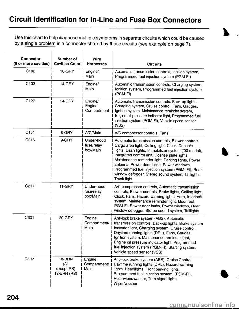
Circuit ldentification for In-Line and Fuse Box Connectors
Use this chart to help diagnose multiple symptoms in separate circuits which could be caused
by a single problem in a connector shared by those circuits (see example on page 7).
Connector
(6 or more cavities)
Number of
Cavities-Color
Wire
Harnesses
Engine/
Main
Engine/
Engine
Compartment
I Automatic transmission controls, lgnition system,
i Programmed fuel injection system (PGM-F|)
Automatic transmission controls, Charging system,
lgnition system, Programmed fuel injection system(PGM-FI)
Automatic transmission controls, Back-up lights,
Charging system, Cruise control, Fans, Gauges,
lgnition system, Maintenance reminder system,
Engine oil pressure indicator light, Programmed fuel
injection system (PGM-Fl), Vehicle speed sensor
ffss)
| {c/Main! A,/C compressor controls, Fans
Under-hood
fuse/relay
box/Main
Automatic transmission controls, Blower controls,
Cargo area light, Ceiling light, Clock, Console
lights, Dash lights, lmmobilizer system ('00 model),
Integrated control unit, License plate lights,
Maintenance reminder light, Parking lights, Power
antenna, Power door locks, Power windows,
Programmed fuel iniection system (PGM-Fl), Rear
window defogger, Stereo sound system, Taillights,
Trunk lioht
11-GRY
18-BBN
(4il
except BS)
12-BBN (RS)
Under-hood
fuse/relay
box/Main
Engine
CompartmenV
Main
Engine
CompartmenU
Main
lr,/C compressor controls, Automatic transmission
controls, Blower controls, Brake lights, Ceiling light,
Clock, Fans, Hazard warning lights, Horn, Interlock
system, Maintenance reminder light, Moonroof ,PGM-FI, Power door locks, Power windows, Rear
window defogger, Stereo sound system, Taillights
Anti-lock brake system (ABS), Automatic
transmission controls, Back-up lights, Brake system
indicator light, Charging system, Cruise control,
Daytime running lights (DRL), Fans, Gauges,
lgnition system, Maintenance reminder light,
Engine oil pressure indicator light, Programmed
tuel injection system (PGM-F|), Starting system,
Vehicle speed sensor (VSS)
Anti-lock brake system (ABS), Cruise Conkol,
Daytime running lights (DRL), Hazard warning
lights, Headlights, Front parking lights,
Programmed fuel injection system, (PGM-Fl),
Rear wiper/washer, Turn signal lights,
Wiper/washer
204
Page 1633 of 1681
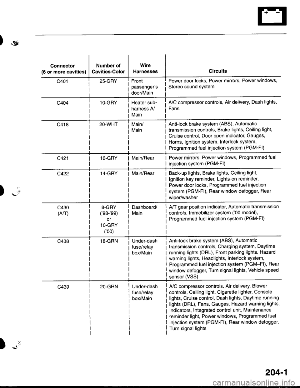
)ot
Connector
(6 or more cavities)
Number of
Cavities-Color
25-GRY
1O-GRY
Wire
Harnesses
Front
passenger's
door/Main
Heater sub-
harness A,/
Main
Circuits
Power door locks, Power mirrors, Power windows,
Stereo sound svstem
fuC compressor controls, Air delivery, Dash lights,
Fans
transmission controls, Brake lights, Ceiling light,
Cruise control, Door open indicator, Gauges,
Horns, lgnition system, Interlock system,
Programmed fuel injection system (PGM-Fl)
Main/
Main
Anti-lock brake system (ABS), Automatic
16.GRYMain/RearPower mirrors, Power windows, Programmed tuel
injection system (PGM-Fl)
14-GRYMain/RearBack-up lights, Brake lights, Ceiling light,
lgnition key reminder, Lights-on reminder,
Power door locks, Programmed fuel iniection
system (PGM-Fl), Rear window defogger, Rear
wiDer/washer) -io
tl
c430
(An)
8-GRY
(e8-'ee)
or
1O-GRY
(00)
18-GRN
Dashboard/
Main
Under-dash
fuse/relay
box/Main
A/T gear position indicator, Automatic transmission
controls, lmmobilizer system ('00 model),
Programmed fuel injection system (PGM-Fl)
Anti-lock brake system (ABS), Automatic
transmission controls, Charging system, Daytime
running lights (DBL), Front parking lights, Hazard
warning lights, Headlights, lnterlock system,
Programmed fuel injection system (PGM-Fl), Rear
window defogger, Turn signal lights, Vehicle speed
c43920-GRNUnder-dash
fuse/relay
box/Main
sensor (VSS
L/C compressor controls, Air delivery, Blower
controls, Ceiling light, Cigarette lighter, Console
lights, Cruise control, Dash lights, Daytime running
lights (DRL), Fans, Gauges, Hazard warning lights,
Indicators, lntegrated control unit, Maintenance
reminder light, Power windows, Programmed fuel
injection system (PGM-Fl), Rear window defogger,
Turn signal lights
)
204-1
Page 1634 of 1681
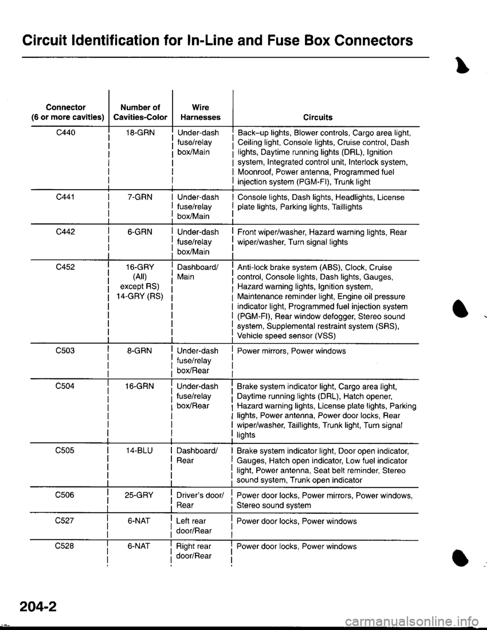
Circuit ldentification for In-Line and Fuse Box Gonnectors
Connector
(6 or more cavities)
Number of
Cavities-Color
18.GRN
Wire
Harnesses
Under-dash
fuse/relay
borMain
Circuits
Back-up lights, Blower controls, Cargo area light,
Ceiling light, Console lights, Cruise control, Dash
lights, Daytime running lights (DRL), lgnition
system, Integrated control unit, Interlock system,
Moonroof, Power antenna, Programmed fuel
injection system (PGM-Fl), Trunk light
7-GRNUnder-dash
fuse/relay
box/Main
Console lights, Dash lights, Headlights, License
plate lights, Parking lights, Taillights
c4426-GRN
16-GRY
(Ail)
except RS)
14-GRY (RS)
16-GRN
Under-dash
tuse/relay
box/Main
Dashboard/
Main
Under-dash
fuse/relay
box/Rear
Under-dash
fuse/relay
box/Rear
Front wiper/washer, Hazard warning lights, Rear
wiper/washer, Turn signal lights
Anti-lock brake system (ABS), Clock, Cruise
control, Console lights, Dash lights, Gauges,
Hazard warning lights, lgnition system,
Maintenance reminder light, Engine oil pressure
indicator light, Programmed fuel injection system
(PGM-Fl), Rear window defogger, Stereo sound
system, Supplemental restraint system (SRS),
Vehicle speed sensor (VSS)
Power mirrors, Power windows
Brake system indicator light, Cargo area light,
Daytime running lights (DRL), Hatch opener,
Hazard warning lights, License plate lights, Parking
lights, Power antenna, Power door locks, Rear
wiper/washer, Taillights, Trunk light, Turn signal
liohts
Dashboard/
Rear
Brake system indicator light, Door open indicator,
Gauges, Hatch open indicator, Low fuel indicator
light, Power antenna, Seat bell reminder, Stereo
sound system, Trunk open indicator
25-GRYDriver's door/
Rear
Left rear
door/Rear
Power door locks, Power mirrors, Power windows,
Stereo sound svstem
I Power door locks, Power windows
lJczat6-NATRight rear
door/Rear
I Power door locks, Power windowsI
a
204-2
Page 1641 of 1681
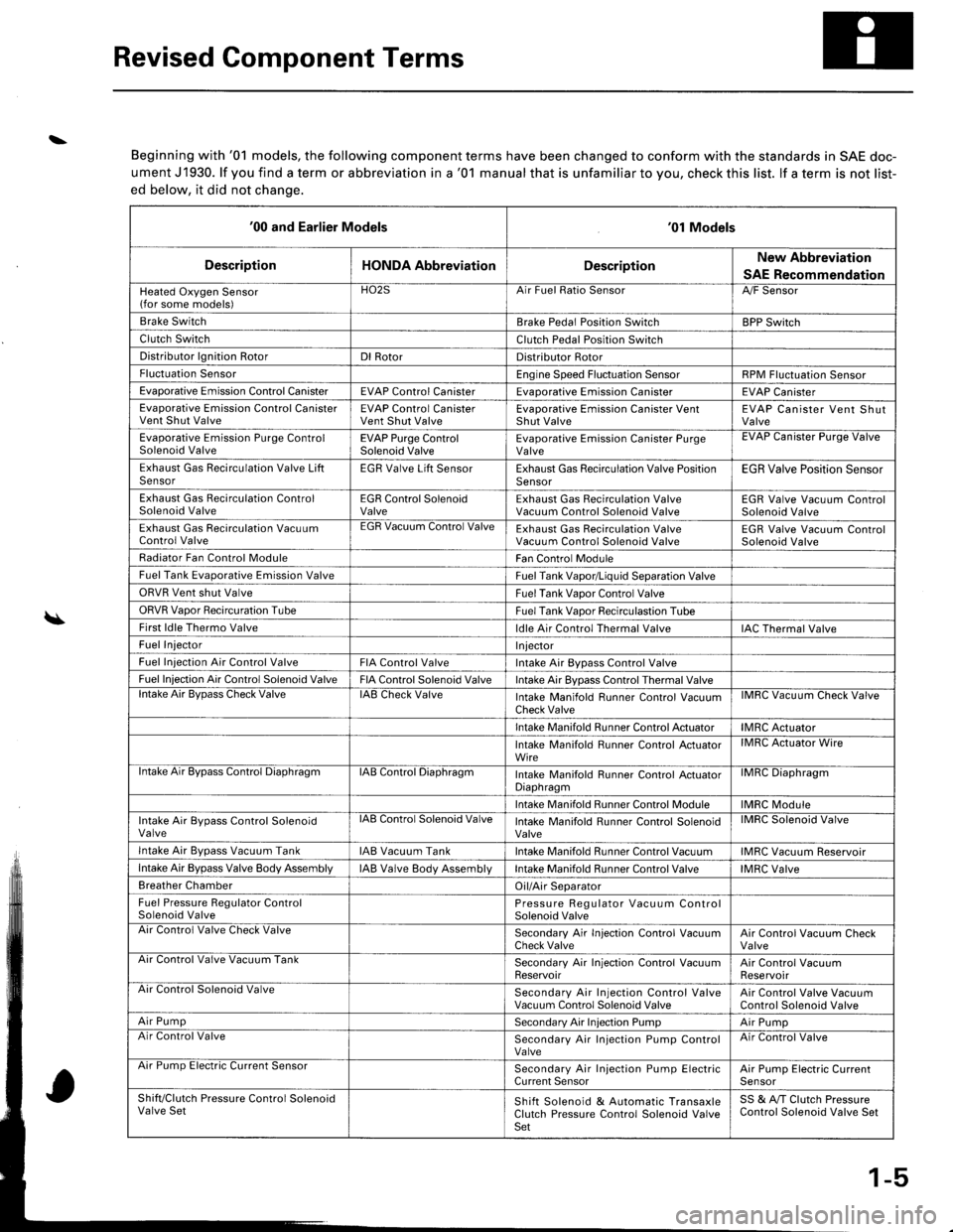
Revised Component Terms
\
\
Beginning with '01 models, the following component terms have been changed to conform with the standards in SAE doc-
ument J1930. lf you find a term or abbreviation in a '01 manual that is unfamiliar to you, check this list. lf a term is not list-
ed below, it did not chanqe.
'00 and Earlier Models'01 Models
DescriptionHONDA AbbreviationDescriptionNew Abbreviation
SAE Recommendation
Heated Oxygen Sensor(for some models)HO2SArr ruet llalto )ensorA,/F Sensor
Brake SwitchBrake Pedal Position SwitchBPP Switch
Clutch SwitchClutch Pedal Position Switch
Distributor lgnition RotorDl RotorDistributor Rotor
Fluctuation SensorEngine Speed Fluctuation SensorRPM Fluctuation Sensor
Evaporative Emission Control CanisterEVAP Control CanisterEvaDorative Emission CanisterEVAP Canister
Evaporative Emission Control CanisterVent Shut ValveEVAP Control CanisterVent Shut ValveEvaporative Emission Canister VentShut ValveEVAP Canister Vent ShutValve
Evaporative Emission Purge ControlSolenoid ValveEVAP Purge ControlSolenoid ValveEvaporative Emission Canister PurgeValveEVAP Uanister Purge Valve
Exhaust Gas Recirculation Valve LiftSensorEGR Valve Lift SensorExhaust Gas Recirculation Valve PositionSensorEGR Valve Position Sensor
Exhaust Gas Recirculation ControlSolenoid ValveEGR Control SolenoidValveExhaust Gas Recirculation ValveVacuum Control Solenoid ValveEGR Valve Vacuum ControlSolenoid Valve
Exhaust Gas Recirculation VacuumControl ValveEGR Vacuum Control ValveExhaust Gas Recirculation ValveVacuum Control Solenoid ValveEGR Valve Vacuum ControlSolenoid Valve
Radiator Fan Control ModuleFan Control Module
Fuel Tank Evaporative Emission ValveFuel Tank Vapor/Liquid Separation Valve
ORVR Vent shut ValveFuel Tank Vaoor Control Valve
ORVR Vaoor Recircuration TubeFuel Tank Vaoor Recirculastion Tube
First ldle Thermo Valveldle Air Control Thermal ValveIAC Thermal Valve
Fuel InjectorI njector
Fuel Iniection Air Control ValveFIA Control ValveIntake Air Bypass Control Valve
Fuel Injection Air Control Solenoid ValveFIA Control Solenoid ValveIntake Air Bypass Control Thermal Valvelntake Air BvDass Check ValveIAB Check ValveIntake Manifold Runner Control VacuumCheck ValveIMRC Vacuum Check Valve
Intake Manifold Runner Control ActuatorIMRC Actuator
Intake Manifold Runner Control ActuatorWireIMRC Actuator Wire
ntake Air Bypass Control DiaphragmIAB Control DiaphragmIntake Manifold Runner control ActuatorDiaphragmilvrr1u urapnragm
Intake Manifold Runner Control ModuleIMRC Module
Intake Air Bypass Control SolenoidValvelAts Control Solenoid ValveIntake Manifold Runner Control SolenoidValveIMRC Solenoid Valve
Intake Air Bvpass Vacuum TankIAB Vacuum TankIntake Manifold Runner Control VacuumIMRC Vacuum Reservoir
Intake Air Bypass Valve Body AssemblyIAB Valve Body AssemblVIntake Manifold Runner Control ValveIMRC Valve
Breather ChamberOil/Air Separator
Fuel Pressure Regulator ControlSolenoid ValvePressure Regulator Vacuum ControlSolenoid ValveAir Control Valve Check ValveSecondary Air In.jection Control VacuumCheck ValveAir Control Vacuum CheckValveArr Control Valve Vacuum TankSecondary Air Injection Control VacuumReservoirAir Control VacuumReservoirAir Control Solenoid ValveSecondary Air Injection Control ValveVacuum Control Solenoid ValveAir Control Valve VacuumControl Solenoid Valve
Air PumpSecondary Air Injection PumpAir PumpAir Control ValveSecondary Air Injection Pump ControlValveAir Control Valve
Arr rump tsreclnc uurrent bensorSecondary Air Injection Pump ElectricCurrent SensorAir Pump Electric CurrenlSensor
Shift/Clutch Pressure Control SolenoidValve SetShift Solenoid & Automatic TransaxleClutch Pressure Control Solenoid ValveSet
SS & A,/T Clutch PressureControl Solenoid Valve Set
1-5
Page 1653 of 1681
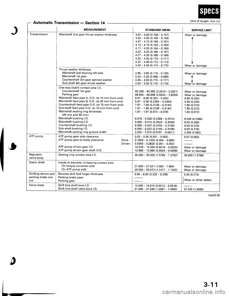
Automatic TransmissionSection 14Unit of length: mm (in)
J
o
c
MEASUREMENTSTANDARD (NEW}SERVICE LIMIT
TransmissionMainshaft 2nd gear thrust washer thickness3.97 - 4.00 (0.1 56 - 0.1 57)4.O2 - 4.05 (0.158 - 0. 1 59)4.07 - 4.10 (0.160 - 0.161 )4.12 - 4.15 (0. 1 62 - 0.163)4.17 - 4.20 (0. 164 - 0. 1 65)4.22 - 4.25 (0.166 - 0.167)4.27 - 4.30 (0.168 - 0. 169)4.32 - 4.35 (0. 170 - 0.171 )4.37 - 4.40 rc.172 - 0.17314.42 - 4.45 (0.174 - 0. 175)
Wear or damage
I
I
IWear or damage
Th rust washer thicknessMainshaft ball bearing left sideMainshaft 1st gearCountershaft 3rd gear splined washerSub-shaft 4th gear thrust washer
2.95 - 3.05 (0.116 - 0.120)2.43 - 2.50 (0.096 - 0.098)4.45 - 4.50 (0.175 - 0.17712.93 - 3.00 (0.1 15 - 0.1 18)
Wear or damage
*""1, damase
One-way clutch contact area l.D.Countershaft lst gearParking gearMainshaft feed pipe A, O.D. (at 15 mm from end)Mainshaft feed pipe B, O.D. (at 30 mm from end)Countershaft feed pipe O.D. (at 15 mm from end)Sub-shaft feed pipe O.D. (at 15 mm from end)Mainshaft sealing ring thickness(29 mm and 35 mm)Mainshaft bushing l.D.Mainshaft bushing LD.Countershaft bushing LD.Sub-shaft bushing l.D.Mainshaft sealing ring groove width
83.339 - 83.365 8.2810 - 3.2821166.685 - 66.698 (2.6254 - 2.6259)8.97 - 8.98 (0.353 - 0.35415.97 - 5.98 (0.2350 - 0.2354)7.97 - 7.98 (0.3138 - 0.3142)7.97 - 7.98 (0.3138 - 0.3142)1.87 - 1.97 (0.074 - 0.078)
6.018 - 6.030 (0.2369 - 0.237 4l9.000 - 9.015 (0.3543 - 0.3549)8.000 - 8.022 (0.3150 - 0.3158)8.000 - 8.022 (0.3150 - 0.3158)2.025 - 2.075 (0.0797 - 0.081 1)
Wear or damageWear or damage8.95 (0.352)
5.95 (0.234)7.95 (0.313)7.95 (0.313)
1.82 (0.0721
6.045 (0.2380)
9.03 (0.356)
8.03 (0.316)8.03 (0.316)
2.095 (0.082)
ATF pumpATF pump gear side clearanceATF pump gear-to-body clearance DriveDrivenATF pump driven gear l.D.ATF pump driven gear shaft O.D.
0.03 - 0.05 (0.001 - 0.00210.1 050 - 0. 1 325 (0.004 - 0.005)0.0350 - 0.0625 (0.001 - 0.002)14.016 - 14.034 (0.5518 - 0.5525)13.980 - 13.990 (0.5504 - 0.5508)
0.07 (0.003)
Wear or damageWear or damageRegulatorvalve bodySealing ring contact area l.D.35.000 - 35.025 (1 .3780 - 1 .3782135.050 (1 .3799)
Stator shaftInside of diameter of bearing contact areaOn torque converter sideOn ATF pump side27 .000 - 27 .021 (1.063 - 1.064)29.000 - 29.013 (1.1417 - 1,1 4221Wear or damageWear or damageShifting device andparking brake con-trol
Reverse shift fork finger thicknessParking brake pawlParking gear
5.90 - 6.00 (0.232 - 0.23615.40 (0.213)
f w"r, o, other defect
Servo bodyShift fork shaft bore LD.Shift fork shaft valve bore l.D.14.000 - 14.010 (0.s512 - 0.5516)37.000 - 37.039 (1.4567 - 1.4582)37.045 (1.4585)
(cont'd)
3-11
Page 1655 of 1681
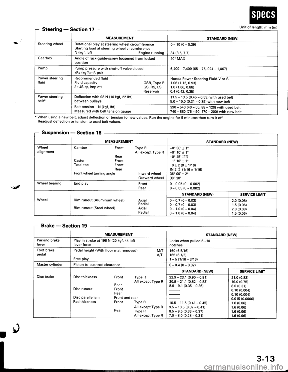
MEASUREMENTSTANDARD (NEWI
Steering wheelRotational play at steering wheel circumferenceStarting load at steering wheel circumferenceN (kgf, lbf) Engine running
0 - 10 (0 - 0.39)
34 (3.5,7 .71
GearboxAngle of rack-guide-screw loosened from lockedoosition20'MAX
PumpPump pressure with shut-off valve closedkPa (kgf/cm,, psi)6,400 - 7,400 (65 - 75, 924 - 1,067],
Power steeringfluidRecommended fluidFluid capacity GSR, Type Rf (US qt, lmp qtl cS, RS, LSReservoir
Honda Power Steering Fluid-V or S1.06 (1.12,0.93)
1.0 (1.06,0.88)
0.4 (0.42, 0.35)
Power steeringbelt*Deflection with 98 N (10 kgf,22 lbflbetween pulleys1 1.5 - 13.5 (0.45 - 0.531 with used belt8.0 - 10.0 (0.31 - 0.39) with new belt
Belt tension N (kgf, lbf)Measured with belt tension gauge390 - 540 (40 - 55, 88 - 120) with used belt740 - 880 (75 - 90, 170 - 2001with new belt
SteeringSection 17
* When using a new belt, adjust deflection or tension to new values. Run the engine for 5 minutes then turn it off.Readiust deflection or tension to used belt values.
Suspension - Section 18
BrakeSection 19
Unit of length: mm (in)
$t
MEASUREMENTSTANDARD (NEWI
WheelalignmentCamber Front Type RAll except Type RRearCaster FrontTotal toe FrontRearFront wheel turning angle Inward wheelOutward wheel
-0'30'r 1"-0' 10'r 1.-0" 45'�1?:i3i1. 10'�1 1.0!210!1116!,lN 2 lf (t7t6 1 1716136. 00'1 2"30'30'
Wheel bearingEnd play FrontRear0 - 0.05 (0 - 0.002)0 - 0.05 (0 - 0.002)
WheelRim runout (Aluminum wheel) AxialRadialRim runout (Steel wheel) AxialRadial
STANDARD (NEW}SERVICE LIMIT
0 - 0.7 (0 - 0.03)0 - 0.7 (0 - 0.03)0 - 1.0 (0 - 0.04)0 - 1.0 (0 - 0.04)
2.0 (0.08)
1.5 (0.06)2.0 (0.08)1.5 (0.06)
MEASUREMENTSTANDARD (NEW}
Parking brakeleverPlay in stroke at 196 N (20 kgf,44 lbf)lever forceLocks when oulled 6 -10
notches
Foot brakepedalPedal height (With floor mat removed)
Free play
M/TAtT160 (6 5/161165 rc 1nl1-5(1/16-3/16)
Master cylinderPiston-to-oushrod clearance0 - 0.4 (0 - 0.021
Disc brakeDisc thickness Front Type RAll except Type RRearDisc runout FrontRearDisc parallelism Front and rearPad thickness Front Type R
All except Type RRear Type RAll except Type R
STANDARD (NEWISERV]CE LIMIT
22.9 - 23.1 (0.90 - 0.91120.9 - 21.1 (0.82 - 0.83)
1= t (0.35-0.361
10.5 - 11.5 (0.41 - 0.45)9.5 - 10.5 (0.37 * 0.41)8.5 - 9.5 (0.33 - 0.37)7.0 - 8.0 (0.28 - 0.31)
21.0 (0.83)19.0 (0.75)
8.0 (0.31)
0.10 (0.004)
0.10 (0.004)
0.015 (0.0006)1.6 (0.06)
1.6 (0.06)1.6 (0.06)
1.6 (0.06)
Page 1659 of 1681
:/
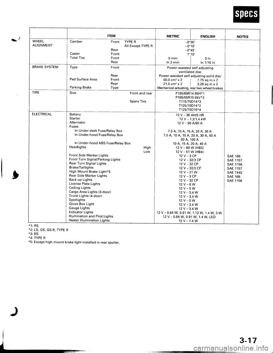
*1: RS*2: LS, GS, GS.R, TYPE R*3: RS+4: TYPE R*5: Except high mount brake light installed in rear spoirer.
ITEMMETRICENGLISHNOTES
WHEELALIGNMENTCamber Front TYPE RAll Except ryPE RRearCaster FrontTotal Toe FrontRear
-0"30'_0"10,_0"45'
1"10'omm I oinIn 2 mm I In 1/16 inBRAKE SYSTEMType Front
RearPad Surface Area FrontRearParking Brake Type
Power-assisted self-adjustingventilated discPower-assisted self-adlusting sol id disc50.0 cm2 x 2 | 7.75 sq in x 221.0 cm, x 2 | a.ZO sq in x 2Mechanical actuating, rear two wheel brakesTIRESize Front and rear
Spare Tire
P195/60R14 85H*1P195/55R15 84V*2T115t0D14*3T125/70D14*2T125n0D15*4
ELECTRICALBatteryStarterAlternatorFusesIn Under-dash Fuse/Relay BoxIn Under-hood Fuse/Relay Box
In Under-hood ABS Fuse/Relay BoxHeadlights
Front Side Marker LightsFront Turn Signal/Parking LightsRear Turn Signal LightsBrake/TaillightsHigh Mount Brake Light*5Rear Side Marker LightsBack-up LightsLicense Plate LightsCeiling LightsCargo Area Lights (3-door)Trunk Lights (4-door)SpotlightsGlove Box LightGauge LightsIndicator Lightslllumination and Pilot LightsHeater lllumination Lights
HighLow
12 V _ 36 AH/5 HR12V -1.2/'t.4kW
12V-90A/85A
7.5 A, 10 A, 15 A, 20 A, 30 A7.5 A. 10 A, 15 A, 20 A, 30 A, 40 A50A,100A10A,15A,20A,40A12V-60W(H83)12V -51 W (HB4)12V-3CP12V _3213 CP12V _32 CP12V-3213CP't2v -21 W12 V - 3 CP12V -32CP
12V_8W12V-5W12V-3.4W12V-3.4W12V_5W12V-3.4W12V-3.4W12 V - 0.84 W, 0.91 W, 1.12W, 1.4W, 3 W12 V - 0.84 W, 0.91 W, 1.4 W, LED12V-1.4W
SAE 168SAE 1157SAE 1156SAE 1157SAE 7440SAE 168SAE 1156
3-17
Page 1664 of 1681
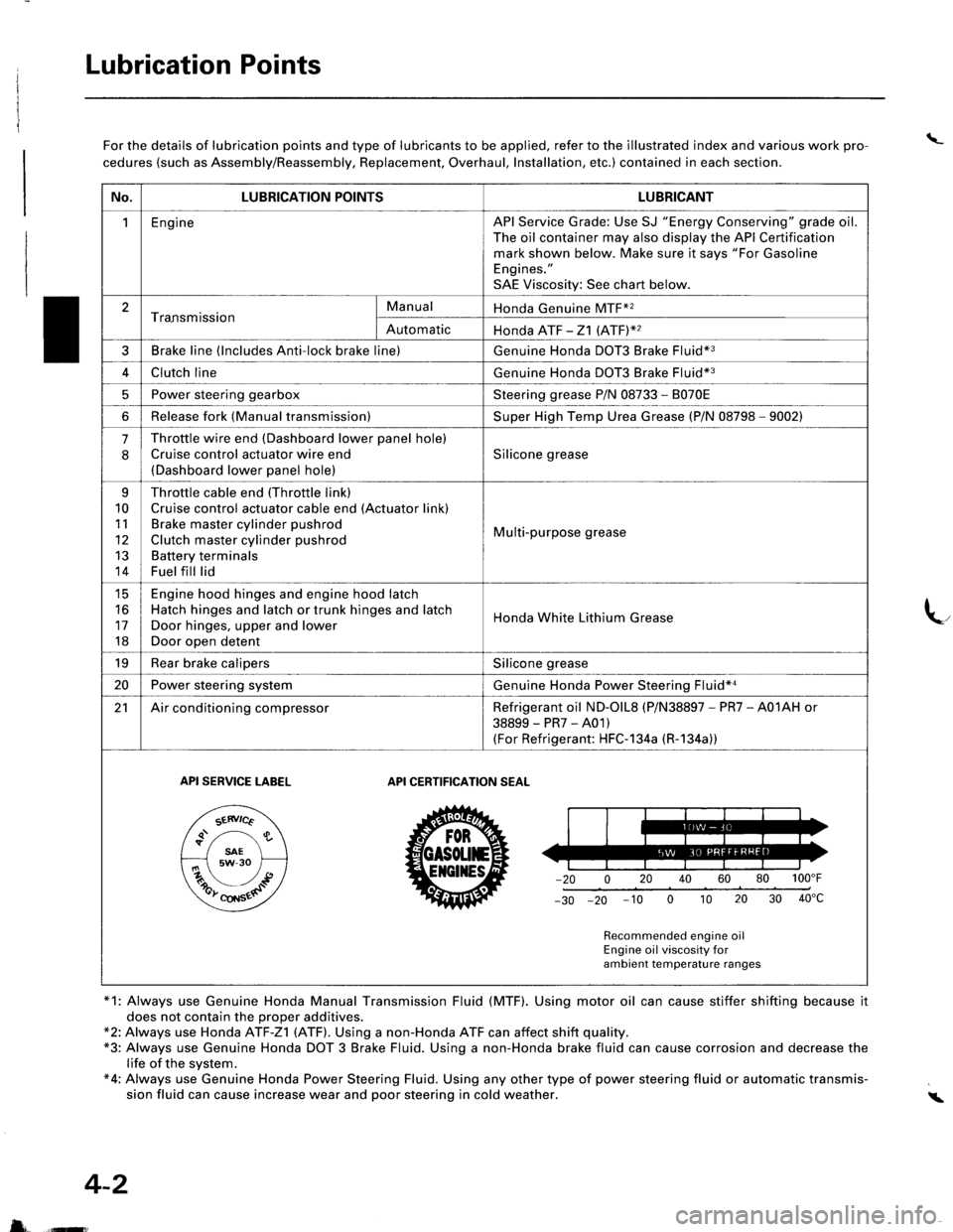
Lubrication Points
\_For the details of lubrication points and type of lubricants to be applied, refer to the illustrated index and various work pro-
cedures (such as Assembly/Reassembly, Replacement, Overhaul, Installation, etc.) contained in each section.
*1: Always use Genuine Honda Manual Transmission Fluid (MTF). Using motor oil can cause stiffer shifting because it
does not contain the proper additives.*2: Always use Honda ATF-Z1 (ATF). Using a non-Honda ATF can affect shift quality.*3: Always use Genuine Honda DOT 3 Brake Fluid. Using a non-Honda brake fluid can cause corrosion and decrease thelife of the system.*4: Always use Genuine Honda Power Steering Fluid. Using any other type of power steering fluid or automatic transmis-sion fluid can cause increase wear and poor steering in cold weather.i
4-2
5 ffi
No.LUBRICATION POINTSLUBRICANT
1EngineAPI Service Grade: Use SJ "Energy Conserving" grade oil.The oil container may also display the API Certificationmark shown below. Make sure it says "For GasolineEngines."
SAE Viscosity: See chart below.
2Tra.nsmissionManualHonda Genuine MTF*2
AutomaticHonda ATF -21 (ATFY2
3Brake line (lncludes Anti-lock brake line)Genuine Honda DOT3 Brake Fluid*3
4Clutch lineGenuine Honda DOT3 Brake Fluid*3
5Power steering gearboxSteering grease P/N 08733 - 8070E
6Release fork (Manual transmission)Super High Temp Urea Grease (P/N 08798 - 9002)
.J
Throttle wire end (Dashboard lower panel hole)
Cruise control actuator wire end(Dashboard lower panel hole)
Silicone grease
q
10
11
12
13
14
Throttle cable end (Throttle link)
Cruise control actuator cable end (Actuator link)Brake master cylinder pushrod
Clutch master cylinder pushrod
Battery terminalsFuel fill lid
Multi-purpose grease
tc
16
17
18
Engine hood hinges and engine hood latchHatch hinges and latch or trunk hinges and latch
Door hinges, upper and lower
Door open detent
Honda White Lithium Grease
19Rear brake calipersSilicone grease
20Power steering systemGenuine Honda Power Steering Fluid*a
21Air conditioning compressorRefrigerant oil ND-olL8 (P/N38897 - PR7 - A01AH or
38899-PR7-A01)(For Refrigerant: HFC-1 34a (R-1 34a))
API SERVICE TABELAPI CERTIFICATION SEAT
ZU30
Recommended engine oilEngine oil viscosity forambient temperature ranges