Page 1214 of 1681
M
lgnition switch at
START iIII)
Check for voltage to ground:
There should be battery voltage.
Blown No.31 (7.5 A) fuse in the
under-dash fuse/relay box
Faulty clutch interlock switch or
starter cut relay (M/T)
Faulty neutral position switch (A/T)
An open in the wire
2D
lgnition switch ON {ll).
brake fluid reservoir
full, and parking brake
tever oown
Connect to ground: Brake
system light should come on.
. Blown brake system light. An open in the wire
Bulb Check System (brake system light)
No. Terminal Test conditionTost: Desiled resultPossiblo cause if lesult is not obtained
)
)
23-157
Page 1222 of 1681

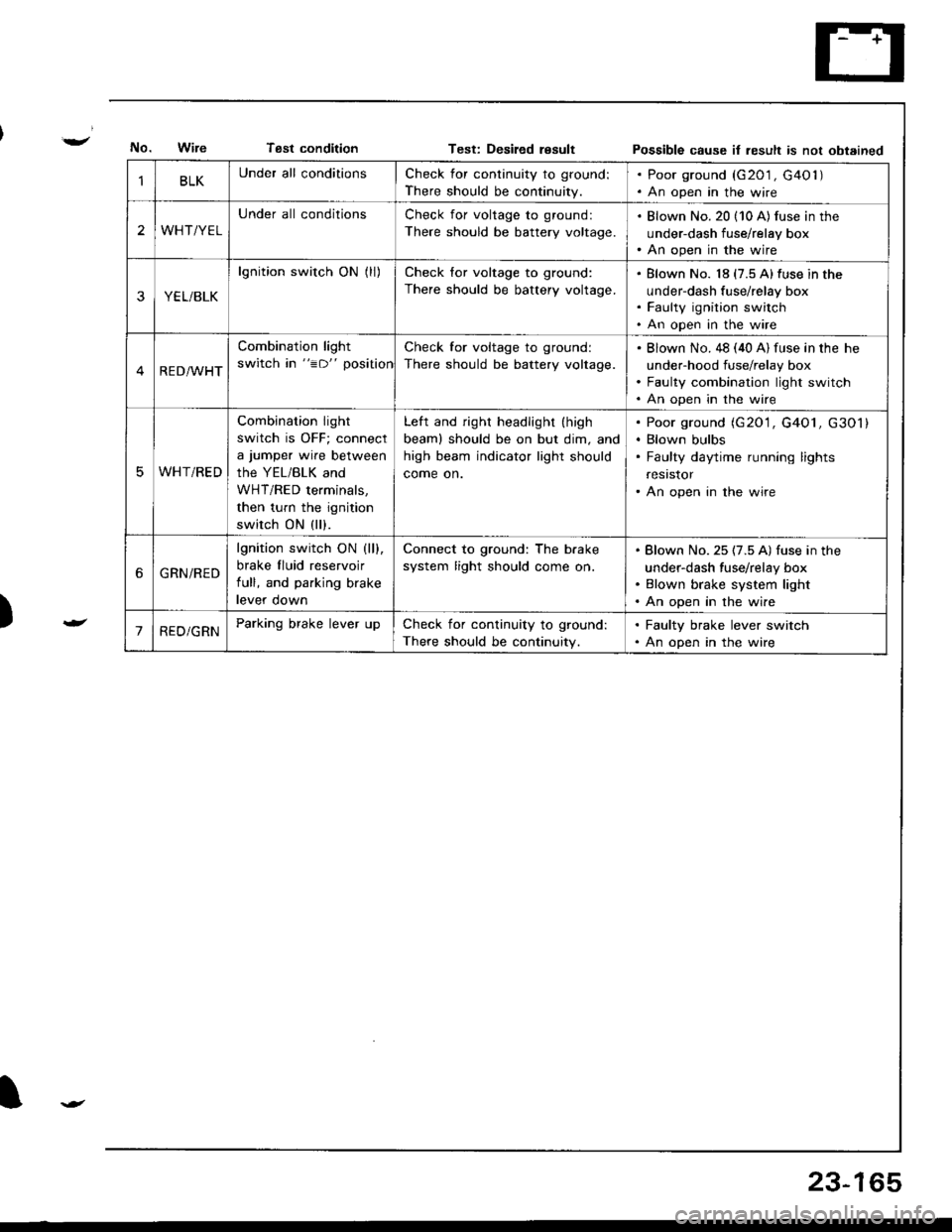
Tsst conditionTest: Desiled resultPossible cause it result is not obtained
)
BLKUnder all conditionsCheck for continuity to ground:
There should be continuity.
. Poor ground (G201 , G40l ). An open in the wire
2WHT/YEL
Under all conditionsCheck for voltage to ground:
There should be battery voltage.
. Blown No. 20 (10 A) fus€ in the
under-dash fuse/relay box. An open in the wire
YEL/BLK
lgnition switch ON (ll)Check for voltage to ground:
There should be battery voltage.
Blown No. 18 (7.5 A)fuse in the
under-dash fuse/relay box
Faulty ignition switch
An open in the wire
RED/WHT
Combination light
switch in "=D" position
Check for voltage to ground:
There should be battery voltage.
Blown No. 48 (40 A) fuse in the he
under-hood fuse/relay box
Faulty combination light switch
An open in the wire
WHT/RED
Combination light
switch is OFF; connect
a jumper wire between
the YEL/BLK and
WHT/RED terminals,
then turn the ignition
switch ON (ll).
Left and right headlight (high
beaml should be on but dim, and
high beam indicator light should
come on.
Poor ground (G20'1, G4O1, G301)
Blown bulbs
Faulty daytime running lights
resrstor
An open in the wire
6GRN/RED
lgnition switch ON (ll).
brake fluid reservoir
full, and parking brake
levef oown
Connect to ground: The b.ake
system light should come on.
Blown No. 25 (7.5 A) fuse in the
under-dash fuse/relay box
Blown brake system light
An open in the wire
'1RED/GRNParking brake lever upCheck for continuity to ground:
There should be continuity.
. Faulty brake lever switch. An open in the wire
23-165
Page 1236 of 1681

J
)
'1.
3.
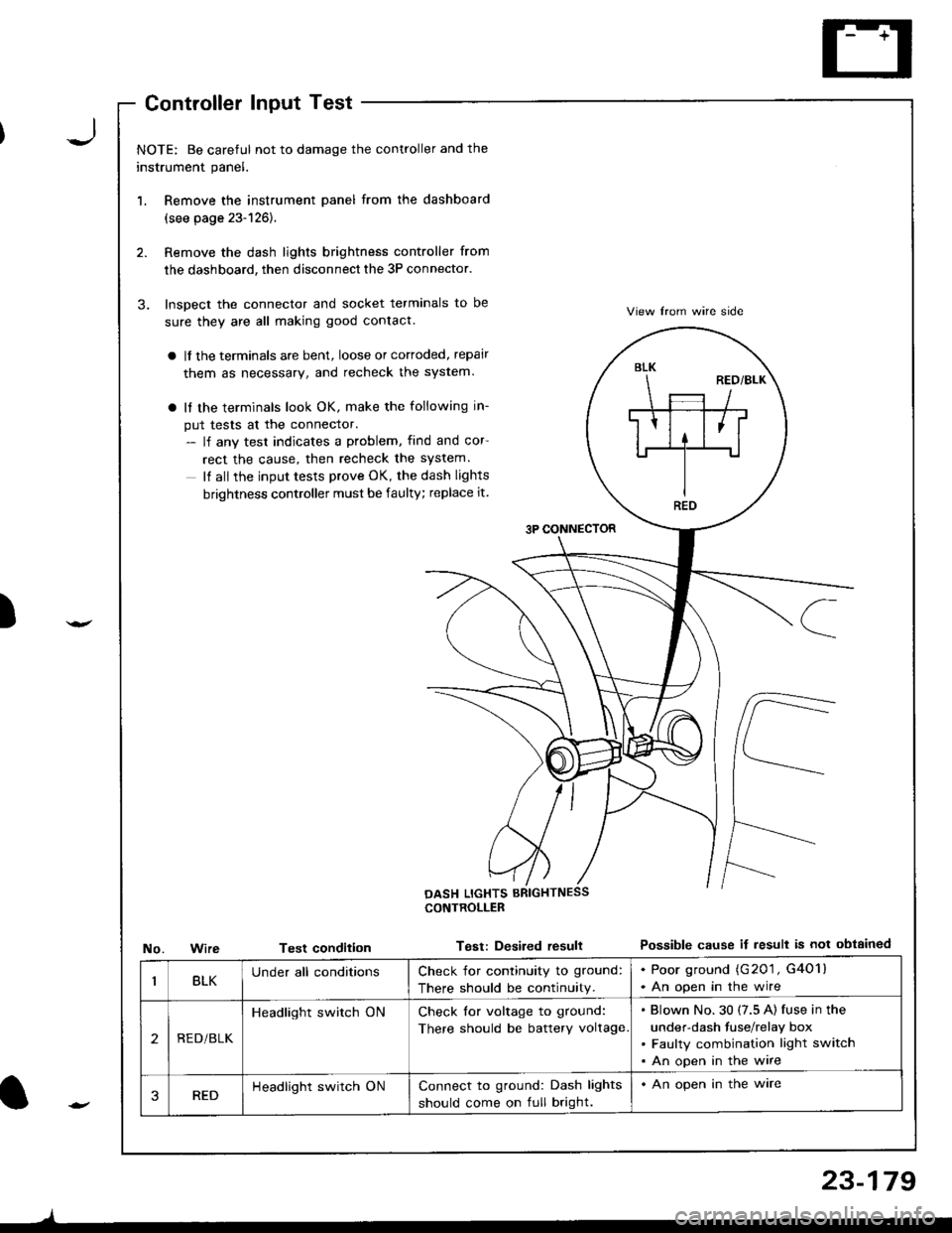
NOTE: Be careful not to damage the controller and the
instrument panel.
Remove the instrument panel from the dashboard
(see page 23-126).
Remove the dash lights brightness controller from
the dashboard, then disconnect the 3P connector.
Inspect the connector and socket terminals to be
sure they are all making good contact.
a lf the terminals are bent, loose or cortoded, repair
them as necessary, and recheck the system.
a It the terminals look OK, make the following in-
put tests at the connector.- lf any test indicates a problem, find and cor
rect the cause, then recheck the system.
It all the input tests prove OK, the dash lights
brightness controller must be faulty; replace it.
3P CONNECTOR
View lrom wire side
Possible cause if result is not obtainedNo.WireTest condition
CONTROLLEB
Test: Desired resull
BLK
REO
BLKUnder all conditionsCheck for continuity to ground:
There should be continuity.
. Poor ground (G201 , G4O1l. An open in the wire
2REDi BLK
Headlight switch ONCheck for voltage to ground:
There should be battery voltage
Blown No.30 (7.5 A) fuse in the
under-dash fuse/relay box
Faulty combination light switch
An open in the wire
3REDHeadlight switch ONConnect to ground: Dash lights
should come on full bright.
. An open in the ware
l-
)
23-179
Page 1251 of 1681

Side Marker/Turn Signal/Hazard Flasher System
Turn Signal/Hazatd Relay Input Test
\
t
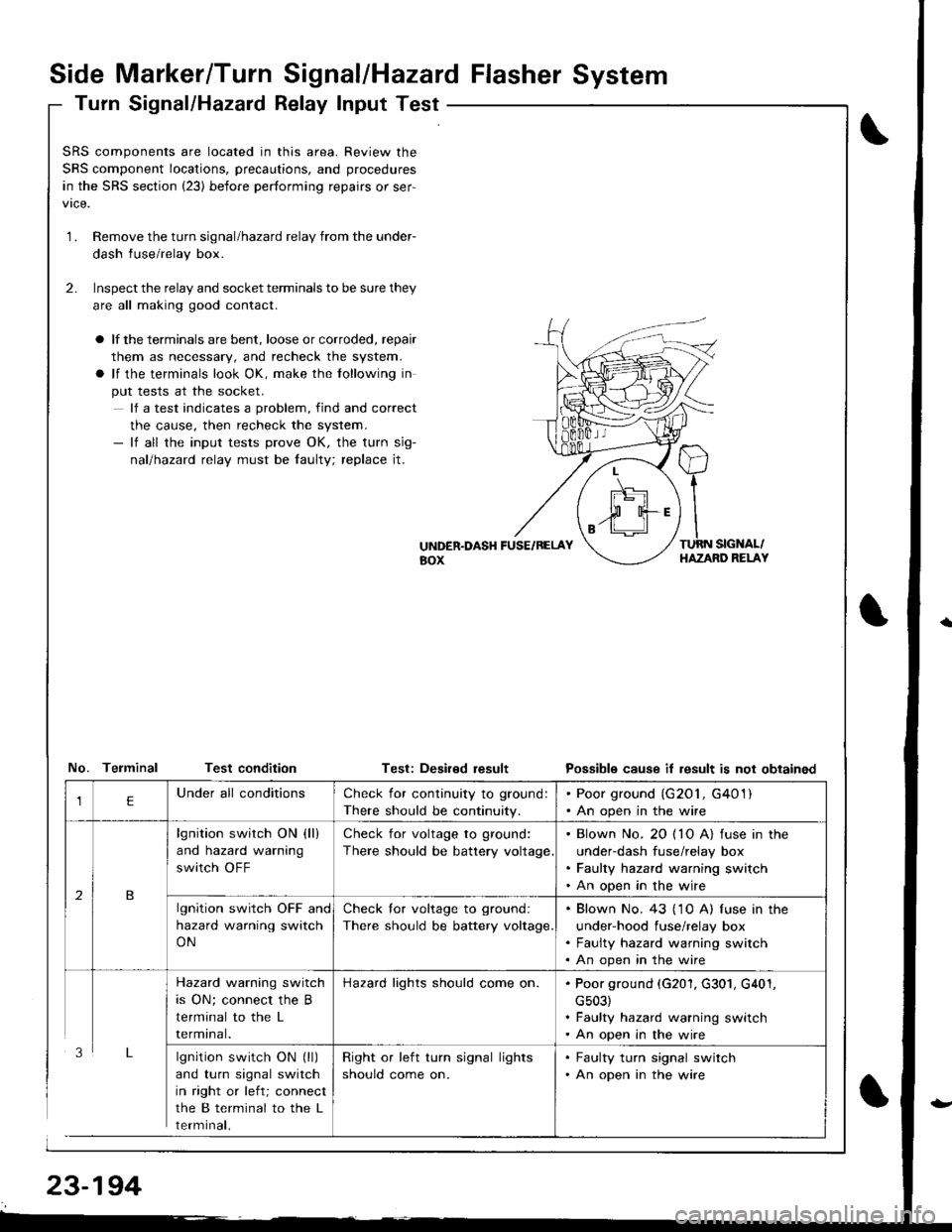
SRS components are located in this area. Review the
SRS component locations, precautions, and procedures
in the SRS section (23) before performing repairs or ser-
1.Remove the turn signal/hazard relay from the under-
dash fuse/relay box.
Inspect the relay and socket terminals to be sure they
are all making good contact.
a lf the terminals are bent, loose or corroded, repair
them as necessary, and recheck the system.
a lf the terminals look OK, make the tollowing in
put tests at the socket.
lf a test indicates a problem, find and correct
the cause, then recheck the system.- lf all the input tests prove OK, the turn sig-
nallhazad relay must be faulty; replace jt.
2.
UiTDER.DASH FUSE/RELAYaox
TURN SIGNAL/HAZAND RELAY
No. Telminal Test conditionTest: Deaired resultPossible cause it result is not obtained
lgnition switch ON (ll)
and turn signal switch
in right or left; connect
the B terminal to the L
rermtnat,
Check for continuity to ground:
There should be continuity.
. Poor ground (G201, G401). An open in the wire
lgnition switch ON (ll)
and hazard warning
switch OFF
Check for voltage to ground:
There should be battery voltage
. Blown No. 20 ( 10 A) fuse in the
under-dash fuse/relay box. Faulty hazard warning switch. An open in the wire
lgnition switch OFF and
hazard warning switch
ON
Check lor voltage to ground:
There should be battery voltage.
. Blown No. 43 ('1 0 A) f use in the
under-hood fuse/relay box. Faulty hazard warning switch. An open in the wire
Hazard warning switch
is ON; connect the B
terminal to the L
rermtnat.
Hazard lights should come on.. Poor ground (G201, G301, G401,
cs03). Faulty hazard warning switch. An open in the wire
Right or left turn signal lights
should come on.
. Faulty turn signal switch. An open in the wire
Page 1253 of 1681
Stereo Sound System
Component Location Index
DOORSPEAKERReplacement, page 23-2OO
NOTE: The original radio has a coded theft protection
circuit. Be sure to get the customer's code number betore- disconnecting the battery.- removing the No.47 (7.5 A) fuse from the under-
hood fuse/relay box.- removing the radio.
After service, reconnect power to the radio and turn it
on. When the word "CODE" is displayed, enter the cus-
tomer's 5 digit code to restore radio operation.
STEREO RADIO/CASSETTEPLAYERRemoval, page 23-199Terminals, page 23 200
RIGHT TWEETERReplacement, page 23'200
BIGHT REARSPEAKERReplacement, page 23-201
LEFT REARSPEAKERReplacement, page 23,201POWER ANTENNA MOTORTest, page 23-202Replacernent, page 23-203
23-196
Page 1256 of 1681
Unit Removal
NOTE: The original radio has a coded thelt protection
circuit. Be sure to get the customer's code number before- disconnecting the battery.- removing the No. 47 (7.5 A) fuse in the under-hood
fuse/relay box.- removing the radio.
After service. reconnect power to the radio and turn it on.
When the word "CODE" is displayed, enter the cus-
tomer's 5-digit code to restore radio operation.
'1. Remove the center console (see section 20).
2. Remove the cigarette lighter assembly (see page
23-2131.
)
FRONT CONSOLE
Remove the four mounting screws, then remove the
front console.
Loosen the two mounting screws. then disconnect
the 16P connector and the antenna lead, and Dull
out the stereo radio/cassette plaver.
16P CONNECTOR
ANTENNA SUB-LEAD
23-199
Page 1259 of 1681

3.
1.
wel
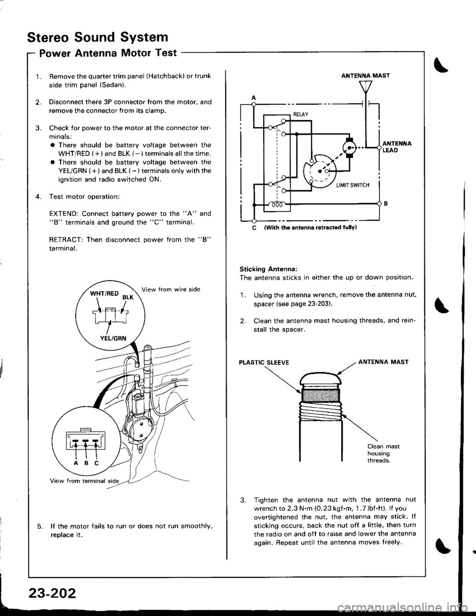
Remove the quarter trim panel (Hatchback) or trunk
side trim panel {Sedan).
Disconnect there 3P connector from the motor, and
remove the connector from its clamp.
Check for power to the motor at the connector ler-
minals:
a There should be battery voltage between the
WHT/RED {+) and BLK {-) terminals allthetime.
a There should be battery voltage between the
YEL/GRN (+) and BLK (-) terminals only withthe
ignition and radio switched ON.
Test motor operation:
EXTEND: Connect battery power to the "A" and"B" terminals and ground the "C" terminal.
RETRACT: Then disconnect power from the "B"
terminal.
lf the motor lails to run or does not run smoothly,
replace it.
WHT/RED BLK
Ttffiliu/^
YEL/GRN
ANTENNA MAST
Sticking Antenna:
The antenna sticks in either the up or down position.
Using the antenna wrench, remove the antenna nut.
spacer (see page 23-203).
Clean the antenna mast housing threads, and rein-
stall the spacer.
2.
1.
PLASTIC SLEEVEANTENNA MAST
Tighten the antenna nut with the antenna nut
wrench to 2.3 N.m {O.23 kgf.m, 1 .7 lbf.ft}. lf you
overtightened the nut, the antenna may slick. lf
sticking occurs, back the nut off a little, then turn
the radio on and off to raise and lower the antenna
again. Repeat until the antenna moves lreely.
c lwith tho anronn6 rotractod lully)
Stereo
Po
Sound
Antenna
System
Motor Test
\
Page 1263 of 1681
Clock
CircuitDiagram
CAUTION:
a Prv the clock out at the left side.
a Be careful not to damage the clock and the dashboard
when prying the clock out.
1. Pry the clock out from the dashboard. then discon-
nect the 4P connector.
4P CONNECTOR
CLOCK
BATTERY
UNDER,HOODFUSE/RELAYBOX
WI-]T/BLK
I
A/ BAT I 1GN TION
Y*"t No3o(7.sA)-|" -v
F'nrrn l
I
WHT/BLU
l- wHT 8LU
al-
STEREO BADIOiCASSETTE PLAYEF
BLK
G201G401
BLKGround
BYELrG1
pry,
(Main clock power sup-
cRE D/BLKLights-on signal
DWHT/BLUConstant power
(Time memory)
Terminals
23-206