1998 HONDA INTEGRA engine oil
[x] Cancel search: engine oilPage 1634 of 1681
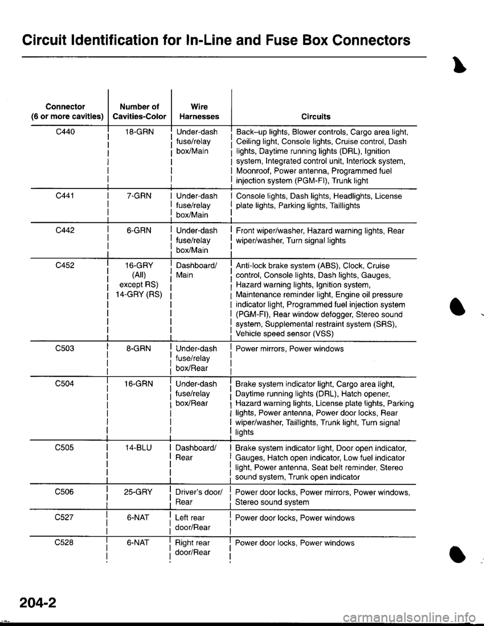
Circuit ldentification for In-Line and Fuse Box Gonnectors
Connector
(6 or more cavities)
Number of
Cavities-Color
18.GRN
Wire
Harnesses
Under-dash
fuse/relay
borMain
Circuits
Back-up lights, Blower controls, Cargo area light,
Ceiling light, Console lights, Cruise control, Dash
lights, Daytime running lights (DRL), lgnition
system, Integrated control unit, Interlock system,
Moonroof, Power antenna, Programmed fuel
injection system (PGM-Fl), Trunk light
7-GRNUnder-dash
fuse/relay
box/Main
Console lights, Dash lights, Headlights, License
plate lights, Parking lights, Taillights
c4426-GRN
16-GRY
(Ail)
except RS)
14-GRY (RS)
16-GRN
Under-dash
tuse/relay
box/Main
Dashboard/
Main
Under-dash
fuse/relay
box/Rear
Under-dash
fuse/relay
box/Rear
Front wiper/washer, Hazard warning lights, Rear
wiper/washer, Turn signal lights
Anti-lock brake system (ABS), Clock, Cruise
control, Console lights, Dash lights, Gauges,
Hazard warning lights, lgnition system,
Maintenance reminder light, Engine oil pressure
indicator light, Programmed fuel injection system
(PGM-Fl), Rear window defogger, Stereo sound
system, Supplemental restraint system (SRS),
Vehicle speed sensor (VSS)
Power mirrors, Power windows
Brake system indicator light, Cargo area light,
Daytime running lights (DRL), Hatch opener,
Hazard warning lights, License plate lights, Parking
lights, Power antenna, Power door locks, Rear
wiper/washer, Taillights, Trunk light, Turn signal
liohts
Dashboard/
Rear
Brake system indicator light, Door open indicator,
Gauges, Hatch open indicator, Low fuel indicator
light, Power antenna, Seat bell reminder, Stereo
sound system, Trunk open indicator
25-GRYDriver's door/
Rear
Left rear
door/Rear
Power door locks, Power mirrors, Power windows,
Stereo sound svstem
I Power door locks, Power windows
lJczat6-NATRight rear
door/Rear
I Power door locks, Power windowsI
a
204-2
Page 1641 of 1681
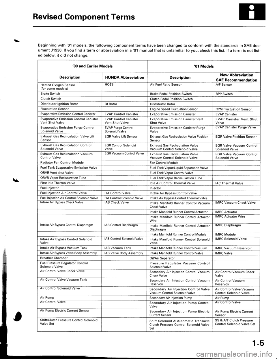
Revised Component Terms
\
\
Beginning with '01 models, the following component terms have been changed to conform with the standards in SAE doc-
ument J1930. lf you find a term or abbreviation in a '01 manual that is unfamiliar to you, check this list. lf a term is not list-
ed below, it did not chanqe.
'00 and Earlier Models'01 Models
DescriptionHONDA AbbreviationDescriptionNew Abbreviation
SAE Recommendation
Heated Oxygen Sensor(for some models)HO2SArr ruet llalto )ensorA,/F Sensor
Brake SwitchBrake Pedal Position SwitchBPP Switch
Clutch SwitchClutch Pedal Position Switch
Distributor lgnition RotorDl RotorDistributor Rotor
Fluctuation SensorEngine Speed Fluctuation SensorRPM Fluctuation Sensor
Evaporative Emission Control CanisterEVAP Control CanisterEvaDorative Emission CanisterEVAP Canister
Evaporative Emission Control CanisterVent Shut ValveEVAP Control CanisterVent Shut ValveEvaporative Emission Canister VentShut ValveEVAP Canister Vent ShutValve
Evaporative Emission Purge ControlSolenoid ValveEVAP Purge ControlSolenoid ValveEvaporative Emission Canister PurgeValveEVAP Uanister Purge Valve
Exhaust Gas Recirculation Valve LiftSensorEGR Valve Lift SensorExhaust Gas Recirculation Valve PositionSensorEGR Valve Position Sensor
Exhaust Gas Recirculation ControlSolenoid ValveEGR Control SolenoidValveExhaust Gas Recirculation ValveVacuum Control Solenoid ValveEGR Valve Vacuum ControlSolenoid Valve
Exhaust Gas Recirculation VacuumControl ValveEGR Vacuum Control ValveExhaust Gas Recirculation ValveVacuum Control Solenoid ValveEGR Valve Vacuum ControlSolenoid Valve
Radiator Fan Control ModuleFan Control Module
Fuel Tank Evaporative Emission ValveFuel Tank Vapor/Liquid Separation Valve
ORVR Vent shut ValveFuel Tank Vaoor Control Valve
ORVR Vaoor Recircuration TubeFuel Tank Vaoor Recirculastion Tube
First ldle Thermo Valveldle Air Control Thermal ValveIAC Thermal Valve
Fuel InjectorI njector
Fuel Iniection Air Control ValveFIA Control ValveIntake Air Bypass Control Valve
Fuel Injection Air Control Solenoid ValveFIA Control Solenoid ValveIntake Air Bypass Control Thermal Valvelntake Air BvDass Check ValveIAB Check ValveIntake Manifold Runner Control VacuumCheck ValveIMRC Vacuum Check Valve
Intake Manifold Runner Control ActuatorIMRC Actuator
Intake Manifold Runner Control ActuatorWireIMRC Actuator Wire
ntake Air Bypass Control DiaphragmIAB Control DiaphragmIntake Manifold Runner control ActuatorDiaphragmilvrr1u urapnragm
Intake Manifold Runner Control ModuleIMRC Module
Intake Air Bypass Control SolenoidValvelAts Control Solenoid ValveIntake Manifold Runner Control SolenoidValveIMRC Solenoid Valve
Intake Air Bvpass Vacuum TankIAB Vacuum TankIntake Manifold Runner Control VacuumIMRC Vacuum Reservoir
Intake Air Bypass Valve Body AssemblyIAB Valve Body AssemblVIntake Manifold Runner Control ValveIMRC Valve
Breather ChamberOil/Air Separator
Fuel Pressure Regulator ControlSolenoid ValvePressure Regulator Vacuum ControlSolenoid ValveAir Control Valve Check ValveSecondary Air In.jection Control VacuumCheck ValveAir Control Vacuum CheckValveArr Control Valve Vacuum TankSecondary Air Injection Control VacuumReservoirAir Control VacuumReservoirAir Control Solenoid ValveSecondary Air Injection Control ValveVacuum Control Solenoid ValveAir Control Valve VacuumControl Solenoid Valve
Air PumpSecondary Air Injection PumpAir PumpAir Control ValveSecondary Air Injection Pump ControlValveAir Control Valve
Arr rump tsreclnc uurrent bensorSecondary Air Injection Pump ElectricCurrent SensorAir Pump Electric CurrenlSensor
Shift/Clutch Pressure Control SolenoidValve SetShift Solenoid & Automatic TransaxleClutch Pressure Control Solenoid ValveSet
SS & A,/T Clutch PressureControl Solenoid Valve Set
1-5
Page 1644 of 1681
I
I
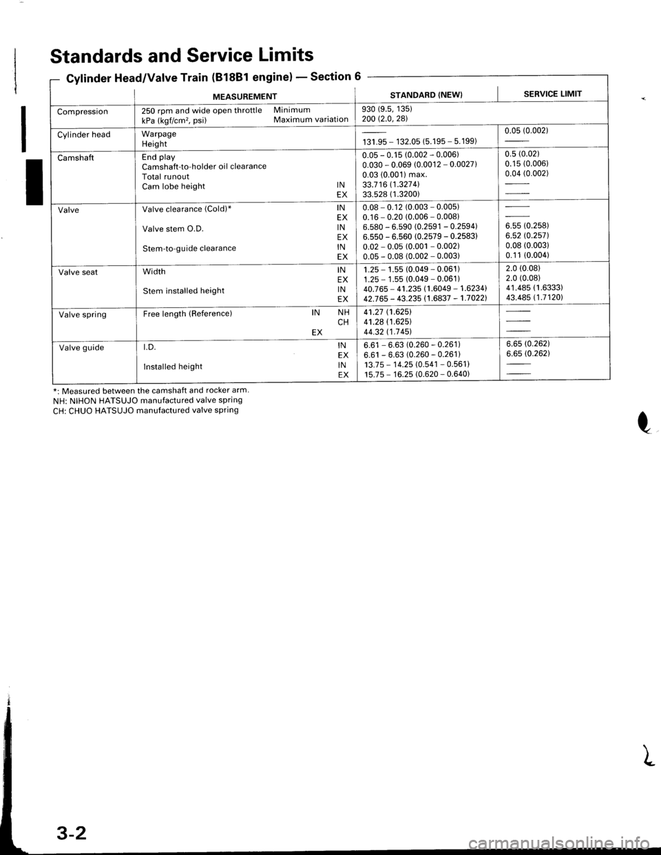
Standards and Service Limits
Cylinder Head/Valve Train (B18Bl engine)Section 6
*: Measured between the camshaft and rocker arm.
NH: NIHON HATSUJO manufactured valve spring
CH: CHUO HATSUJO manufactured valve spring
MEASUREMENTSTANDARD (NEW) I SERVICE LIMIT
Compression250 rpm and wide open throttle Minimum
kPa (kgf/cm'�, psi) Maximum variation930 (9.5, 135)200 Q.0,281
Cylinder headWarpageHeightta,|* - 132.05 (5.195 - 5.199)0.05 (0.002)
CamshaftEnd playCamshaft-to-holder oil clearanceTotal runoutCam lobe height lNEX
0.05 - 0.15 (0.002 - 0.006)0.030 - 0.069 (0.0012 - 0.0027)0.03 (0.001) max.33.7 16 11.327 4l33.528 ( 1.3200)
0.5 (0.02)
0.15 (0.006)
0.04 (0.002)
ValveValve clearance (Cold)" lNEX
Valve stem O.D. lNEX
Stem-to-guide clearance lNEX
0.08 - 0.12 (0.003 - 0.005)0.16 - 0.20 (0.006 - 0.00816.580 - 6.590 (0.2591 - 0.2594)6.550 - 6.560 (0.2579 - 0.2583)
0.02 - 0.05 (0.001 - 0.002)0.05 - 0.08 (0.002 - 0.003)
ouu to.rutt6.52 rc.2571.0.08 (0.003)
0.1 1 (0.004)
Valve seatwidth lNEX
stem installed height lNEX
1 .25 - 1.55 (0.049 - 0.061 )1.25 - 1 .55 (0.049 - 0.061 )40.765 - 41.235 (1.6049 - 1.6234142J65 - 43.235 (1.6837 - 1.70221
2.0 (0.08)
2.0 (0.08)
41.485 (1.6333)
43.485 (1.71201
Valve springFree length (Reference)IN NHCHEX
41.27 (1.6251
41.28 (1.625)
44.32 t1-7 451
Valve guidet.D. lNEX
Installed height lNEX
6.61 - 6.63 (0.260 - 0.261)6.61 - 6.63 (0.260 - 0.261)13.7 5 - 1 4.25 (0.541 - 0.561 )15.75 - 16.25 (0.620 - 0.640)
6.6s (0.262)
6.65 (0.262)
Page 1645 of 1681
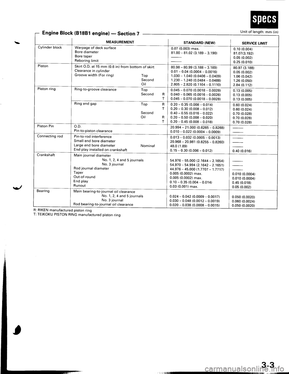
Engine Block (81881 engine)Section 7Unit of length: mm (in)
3-3
\
Yl
R: RIKEN manufactured piston ringT: TEIKOKU PISTON RING manufactured piston ring
E' - Declror
MEASUREMENTSTANDARD (NEW}SERVICE LIMITCylinder blockWarpage of deck surfaceBore diameterBore taperReboring limit
0.07 (0.003) max.81.00 - 81.02 (3.189 - 3.190)0.10 (0.004)
81.07(3.192)0.05 (0.002)
0.25 (0.010)PistonSkirt O.D. at 15 mm (0.6 in) from bottom of skirtClearance in cylinderGroove width (For ring) TopSecondoil
80.98 - 80.99 (3. 1 88 - 3. 1 89)0.01 - 0.04 (0.0004 - 0.0016)1 .030 - 1.040 (0.0406 - 0.0409)1.230 - 1.240 (0.0484 - 0.0488)2.805 - 2.820 (0.1 104 - 0. 1 1 10)
80.97 (3.188)
0.05 (0.002)1.06 (0.042)
1.26 (0.050)
2.84 (0.112!.Piston ringRing-to-groove clearance TopSecond RT
0.045 - 0.070 (0.0018 - 0.0028)0.040 - 0.065 (0.0016 - 0.0026)0.045 - 0.070 (0.0018 - 0.0028)
0.13 (0.0051
0.13 (0.005)
0.13 (0.005)
Ring end gap Top
Secondoil
HT
RT
0.20 - 0.35 (0.008 - 0.014)0.20 - 0.30 (0.008 - 0.012)0.40 - 0.55 (0.016 - 0.022)0.20 - 0.50 (0.008 - 0.020)0.20 - 0.45 (0.008 - 0.018)
0.60 (0.024)
0.60 (0.024)
0.70 (0.028)
0.70 (0.028)
0.70 (0.028)Piston Pino.D.Pin-to-piston clearance20.994 - 21.000 (0.8265 - 0.8268)0.010 - 0.022 (0.0004 - 0.0009)Connecting rodPin-to-rod interferenceSmall end bore diameterLarge end bore diameter NominalEnd play installed on crankshaft
0.013 - 0.032 (0.0005 - 0.0013)20.968 - 20.981 (0.8255 - 0.8260)48.0 (1 .89)0.15 - 0.30 (0.006 - 0.012)0.40 (0.016)CrankshaftMain journal diameterNo. 1, 2, 4 and 5 journalsNo. 3 journalRod journal diameterTaperOut-of-roundEnd playRunout
54.976 - 55.000 (2.1644 - 2.1654)54.970 - 54-994 (2.1642 - 2.1651144.976- 45.000 (1.7707 - 1.771710.005 (0.00021 max.0.005 (0.0002) max.0.10 - 0.35 (0.004 - 0.014)0.03 (0.001) max.
0.010 (0.0004)0.010 (0.0004)
0.45 (0.018)
0.05 (0.002)Bea ringMain bearing-to-journal oil crearanceNo. 1, 2, 4 and 5 journalsNo. 3 journalRod bearing-to-journal oil crearance
0.024 - 0.042 (0.0009 - 0.0017)0.030 - 0.048 (0.0012 - 0.0019)0.020 - 0.038 (0.0008 - 0.0015)
0.050 (0.0020)
0.060 (0.0024)0.0s0 (0.0020)
L rlllllllllrltruE
Page 1647 of 1681
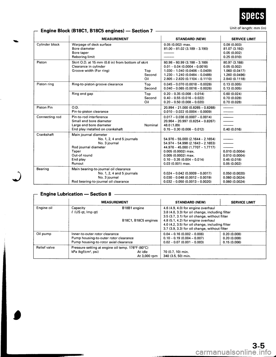
Unit of length: mm (in}
J
Engine Block (818C1, 818C5 engines)Section 7
Engine LubricationSection 8
MEASUREMENTSTANDARD (NEW} I SERVICE LIMIT
Cylinder blockWarpage of deck surfaceBore diameterBore taperReboring limit
0.05 (0.002) max.81.00 - 81.02 (3.189 - 3.190)0.08 (0.003)
81.07 (3.192)
0.05 (0.002)
0.25 (0.010)
PistonSkirt O.D. at 15 mm (0.6 in) from bottom of skirtClearance in cylinderGroove width (For ring) TopSecondoil
80.98 - 80.99 (3.188 - 3.18910.01 - 0.04 (0.0004 - 0.0016)1.030 - 1.040 (0.0406 - 0.0409)1.230 - 1.240 (0.0484 - 0.0488)2.805 - 2.820 (0.1 104 - 0.1 1 10)
80.97 (3.188)
0.05 (0.002)
1.060 (0.04171
1.260 (0.0496)
2.840 (0.11181
Piston ringRing-to-piston groove clearance TopSecond0.045 - 0.070 (0.0018 - 0.0028)0.040 - 0.065 (0.0016 - 0.0026)0.13 (0.005)
0.13 (0.005)
Ring end gap TopSecondoil
0.20 * 0.35 (0.008 - 0.014)0.40 - 0.55 (0.016 - 0.022)0.20 - 0.50 (0.008 - 0.020)
0.60 (0.024)
0.70 (0.028)
0.70 (0.028)
Piston Pino.D.Pin-to-piston clearance20.994 - 21 .000 (0.8265 - 0.8268)0.010 - 0.022 (0.0004 - 0.0009)
Connecting rodPin-to-rod interferenceSmall end bore diameterLarge end bore diameter NominalEnd play installed on crankshaft
0.017 - 0.036 (0.0007 - 0.0014)20.964 - 20.997 (0.8254 - 0.8267)48.0 (1.89)
0.15 - 0.30 (0.006 - 0.012)0.40 (0.016)
CrankshaftMain journal diameterNo. 1, 2, 4 and 5 journals
No. 3 journalRod journal diameterTaperOut-of roundEnd playRunout
54.976 - 55.000 (2.1644 - 2.1654)54.97 4 - 54.998 (2.1643 - 2.1653)44.976- 45.000 (1.7707 -1.7717l.
0.005 (0.0002) max.0.005 (0.0002) max.0.10 - 0.35 (0.004 - 0.014)0.03 (0.001) max.
orro to.ooool0.010 (0.0004)
0.45 (0.018)
0.05 (0.002)
BearingMain bearing-to-journal oil clearanceNo. 1, 2, 4 and 5 journals
No. 3 journal
Rod bearing-to-journal oil clearance
0.024 - 0.042 (0.0009 - 0.0017)0.030 - 0.048 (0.0012 - 0.0019)0.032 - 0.050 (0.0013 - 0.0020)
0.050 (0.0020)
0.060 (0.0024)
0.060 (0.0024)
MEASUREMENTSTANDARD (NEW}SERVICE LIMIT
Engine oilCapacity 81881 engine/ (US qt, lmp qt)
818C1, B18C5 engines
4.6 (4.9, 4.0) for engine overhaul3.8 (4.0, 3.3) for oil change, including filter3.5 (3.7,3.1)for oil change, without filter4.8 (5.1, 4.2) for engine overhaul4.O (4.2,3.5) for oil change. including filter3.7 (3.9, 3.3) for oil change, without filter
Oil pumplnner-to-outer rotor clearancePump housing-to-outer rotor clearancePump housing-to-rotor axial clearance
0.04 - 0.16 (0.002 - 0.006)0.10 - 0.19 (0.004 - 0.007)0.02 - 0.07 (0.001 - 0.003)
0.20 (0.008)
0.20 (0.008)
0.1s (0.006)
Relief valvePressure setting at engine oil temp. 176'F (80"C)
kPa (kgf/cm,. psi) At idleAt 3,000 rpm70 (0.7, 101 min.340 (3.5, 50) min.
3-5
Page 1649 of 1681
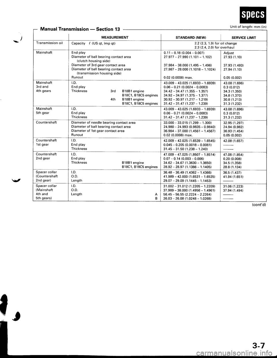
Unit of length: mm (in)Manual TransmissionSection 13
_/
/
MEASUREMENTSTANDARD (NEW}SEBVICE LIMIT
Transmission oilCapacity / (US qt, lmp qt)2.2 12.3, 1.9) for oil change2.3 12.4,2.0) for overhaul
MainshaftEnd playDiameter of ball bearing contact area(clutch housing side)Diameter of 3rd gear contact areaDiameter of ball bearing contact area(transmission housing side)Runout
0.1 1 - 0.18 (0.004 - 0.007)27 .977 - 27.990 (1 .101 - 1.102]|
37.984 - 38.000 (1.495 - 1.496)27.987 - 28.000 (1.1018 - 1.1024l.
0.02 (0.0008) max.
Adiust27 .93 (1.101
37.93 (1 .493)27 .94 11.101
0.05 (0.002)
Mainshaft3rd and4th gears
LD.End playThickness 3rd 81881 engine818C1, B18C5 engines4th 81881 engine818C1, 818C5 engines
43.009 - 43.025 (1 .6933 - 1 .(0.06 - 0.21 (0.0024 - 0.0083)34.42 - 34.47 (1 .355 - 1.357)34.92 - 34.97 (1.37 5 -'�t.377 )30.92 - 30.97 (1.2't7 -'�t.219)
31.42 - 31.47 n.237 - 1.239)
i939)43.0t0.3 ((
34.334.830.831 .3
(1.696)
.01211.350)1.370)1.21311.2321
Mainshaftsth geart.D.End playTh ickness
43.009 - 43.025 (1.6933 - 1.6939)0.06 - 0.21 (0.0024 - 0.0083)31 .42 - 31 .47 11 .237 - 1.2391
43.08 (1.696)
0.3 (0.012)
31.3 11.2321
CountershaftDiameter of needle bearing contact areaDiameter of ball bearing contact areaDiameter of 1st gear contact areaRunout
33.000 - 33.015 (1 .299 - 1 .300)24.980 - 24.993 (0.9835 - 0.9840)36.984 - 37.000 (1.4561 - 1.456710.02 (0.0008) max.
32.95 (1.2971
24.94 (0.982)
36.93 (1 .454)0.05 (0.002)
Countershaft1 st geart.D.End playTh ickness
42.009 - 42.025 (1.6539 - 1.6545)0.045 - 0.205 (0.0018 - 0.0081)31.45 - 31 .50 (1.238 - 1.240)
42.08 (1.657)
Countershaft2nd geart.D.End playThickness 81881 engine818C1, 818C5 engines
47.009 - 47 .025 (1.8507 - 1.8514)0.07 - 0.14 (0.003 - 0.006)34.62 - 34.67 (1 .3630 - 1.3650)28.92 - 28.97 (1.1386 - 1.1405)
47.08 (1 .8s410.20 (0.008)
34.5 (1.358)
28.8 (1.1341
Spacer collar(Countershafl
2nd gear)
t.D.o.D.Length
36.48 - 36.49 (1.4362 - 1.4366)41.989 - 42.000 (1.6531 - 1.6535)29.07 -29.09 (1.1445- 1.14531
36.5 (1 .437)41.94 (1.651)
Spacer collar(Mainshaft
4th and5th gears)
t.D.o.D.Length AB
31 .002 - 31 .012 11 .2205 - 't .2209'37.989 - 38.000 ( 1.4956 - 1.4961 )56.45 - 56.55 (2.2224 - 2.2264'�)26.03 - 26.08 (1.0248 - 1.0268)
31.06 (1 .223)37.94 (1 .494)
(cont'd)
Page 1654 of 1681
MFASIIREMENTSTANDARD (NEW}
Wire Dia.o.D.Free LengthNo. of Goils
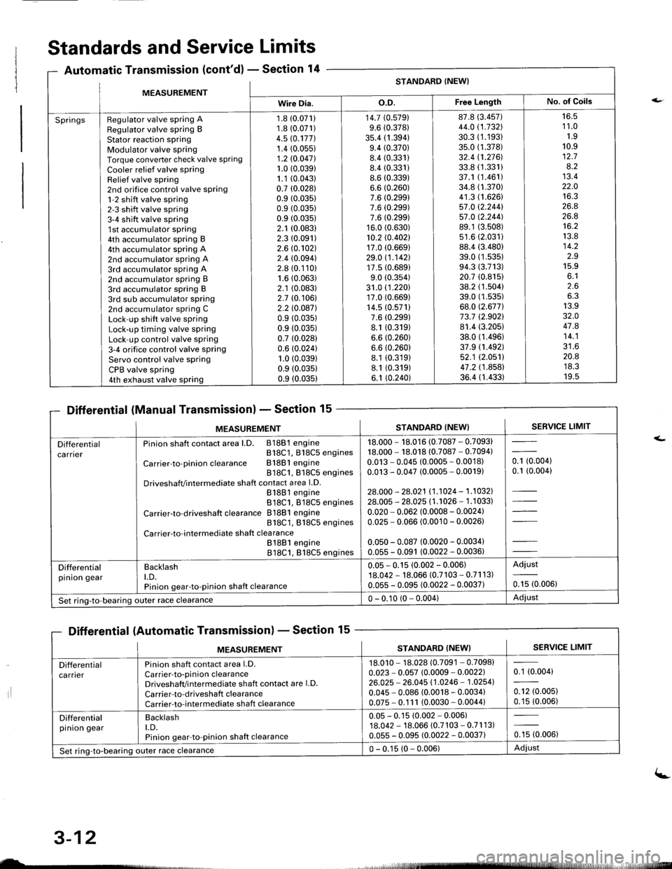
SpringsRegulator valve spring ARegulator valve spring BStator reaction sPringModulator valve springTorque converter check valve springCooler relief valve springRelief valve spring2nd orifice control valve spring1-2 shift valve spring2-3 shift valve spring3-4 shift valve spring1st accumulator spring4th accumulator spring B4th accumulator spring A2nd accumulator spring A3rd accumulator spring A2nd accumulator spring B3rd accumulator spring B3rd sub accumulator spring2nd accumulator spring CLock-up shift valve springLock-up timing valve springLock-up control valve spring3-4 orifice control valve springServo control valve springCPB valve spring4th exhaust valve spring
1.8 (0.071)
1.8 (0.071)
4.5 rc.177].1.4 (0.05s)
1.2 10.047l.1.0 (0.039)
1.1 (0.043)
0.7 (0.0281
0.9 (0.035)
0.9 (0.035)
0.9 (0.035)
2.1 (0.083)
2.3 (0.091)
2.6 (0.102)
2.4 (0.094)
2.8 (0.110)
1.6 (0.063)
2.1 (0.083)
2.7 (0.106)
2.2 l0.o87l0.9 (0.035)
0.9 (0.035)
0.7 (0.028)
0.6 (0.024)
1.0 (0.039)
0.9 (0.0351
0.9 (0.035)
14.7 (0.5791
9.6 (0.378)
35.4 (1 .394)9.4 (0.370)
8.4 (0.331)
8.4 (0.331)
8.6 (0.339)
6.6 (0.260)
7.6 (0.299)
7.6 (0.299)
7.6 (0.299)
16.0 (0.630)
10.2 rc.402117.0 (0.669)
29.0 11.142117.5 (0.689)
9.0 (0.354)
31.0 (1 .220)17.0 (0.669)
14.5 (0.571)
7.6 (0.299)
8.1 (0.319)
6.6 (0.260)
6.6 (0.260)
8.1 (0.319)
8.1 (0.319)
6.1 (0.240)
87.8 (3.457)
44.0 (1.732\
30.3 (1.193)
35.0 (1.378)
32.4 (1.2761.
33.8 (1.331)
37.1 (1.461)
34.8 (1.370)
41.3 (1.626)
57.0 12.244157.0 12.244].89.1 (3.508)
s1.6 (2.0311
88.4 (3.480)
39.0 (1 .53s)94.3 (3.713)
20.7 (0.815)
38.2 (1.504)
39.0 (1.535)
68.0 (2.677)
73.7 (2.9021
81.4 (3.205)
38.0 (1.496)
37.9 (1.492)
52.1 (2.0511
47.2 (1 .858)36.4 (1.433)
16.51 1.01.910.912.78.213.422.01A ?
26.826.8't6.2
13.814.2z.J15.9o. l2.66.313.932.O47.814.1?1 A
20.8ttJ.JI v.5
Standards and Service Limits
Automatic Transmission (cont'd) - Section 14
Differential (Manual Transmission) - Section 15
Differential (Automatic Transmission) - Section 15
ilt5stlrrr, - 4,
MEASUREMENTSTANDARD (NEW}SERVICE LIMIT
Differentialca rnerPinion shaft contact area l.D. 81881 engineB18C1, 818C5 engines
Carrier-to-pinionclearance Bl88lengine818C1, 818C5 enginesDriveshafVintermediate shaft contact area l.D.81881 engine818C1. 818C5 engines
Carrier-to-driveshaft clearance 81881 engine818C1, 818C5 engines
Carrier-to-intermediate shaft clea rance81881 engine818C1, 818C5 engines
18.000 - 18.016 (0.7087 - 0.7093)18.000 - 18.018 (0.7087 - 0.7094)0.013 - 0.045 (0.0005 - 0.0018)0.013 - 0.047 (0.0005 - 0.0019)
28.000 - 28.021 11.1024 - 1.1032].28.005 - 28.025 l1 .'�t026 - 1 .1 033)
0.020 - 0.062 (0.0008 - 0.0024)0.025 - 0.066 (0.0010 - 0.00261
0.050 - 0.087 (0.0020 - 0.0034)0.055 - 0.091 (0.0022 - 0.0036)
- toooot0.1 (0.004)
Differentialpinion gearBacklasht.D.Pinion gear-to-pinion shaft clearance
0.05 - 0.15 (0.002 - 0.006)18.042 - 18.066 (0.7103 - 0.71 1 3)0.055 - 0.095 (0.0022 - 0.0037)
Adjust
0.15 (0.006)
Set ring-to-bearing)uter race clearance0 - 0.10 (0 - 0.004)Adjust
nsmlssaonl - Sectton
MEASUREMENTSERVICE LIMITSTANDARD (NEW}
Differentialca rrierPinion shaft contact area l.D.Carrier-to-pinion clearanceDriveshaft/i ntermediate shaft contact are l.D.
Carrier-to-driveshaft clearanceCarrier-to-intermediate shaft clearance
18.010 - 18.028 (0.7091 - 0.7098)0.023 - 0.057 (0.0009 - 0.0022)26.025 - 26.045 11.0246 - 1.02541
0.045 - 0.086 (0.0018 - 0.0034)0.075 - 0.1 11 (0.0030 - 0.0044)
0.1 (0.004)
0.12 (0.005)
0.15 (0.006)
Differentialpinion gearBacklasht.D.Pinion gear-to-pinion shaft clearance
0.05 - 0.15 (0.002 - 0.006)18.042 - 18.066 (0.7 103 - 0.71 1 3)0.055 - 0.095 (0.0022 - 0.0037)0.15 (0.006)
Set ring-to-bearing outer race clearance0 - 0.15 (0 - 0.006)Adiust
uL-
3-12
(-
Page 1656 of 1681
ng
MEASUREMENTSTANDARD {NEW}
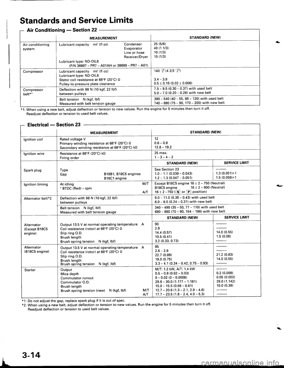
Air conditioningsystemLubricant capacity m/ (fl oz) CondenserEvaporatorLine or hoseReceiver/Drver
Lubricant type: ND-OlL8(P/N 38897 - PR7 - A01AH or 38899 - PR7 - A01)
25 1516l40 (1 1/3)10 (1/3)
10 (1/3)
CompressorLubricant capacity m/ (fl oz)Lubricant type: ND-OlL8Stator coil resistance at 68'F (20"C) OPulley-to-pressure plate clearance
140'�trs 142B'�y'�l
3.4 - 3.80.5 I 0.15 (0.02 1 0.006)
Compressorbelt*rDeflection with 98 N (10 kgf. 22 lbf)between pulleys
7.5 - 9.5 (0.30 - 0.37) with used belt5.0 - 7.0 (0.20 - 0.281 with new belt
Belt tension N (kgf, lbf)Measured with belt tension gauge390 - 540 (40 - 55, 88 - 120) with used belt740 - 880 (75 - 90, 170 - 200) with new belt
*1: When using a new belt, adjust deflection or tension to new values. Run the engine for 5 minutes then turn it off.
Standards and Service Limits
Air Conditionins - Section 22
Readjust deflection or tension to used belt values.
Electrical - Section 23
f1: Do not adjust the gap, replace spark plug if it is out of spec'*2: When using a new belt. adjust deflection or tension to new values. Run the engine for 5 minutes then turn it off.
Readjust deflection or tension to used belt values.
a.
t-
MEASUREMENTSTANDARD (NEW}
lgnition coilRated voltage VPrimary winding resistance at 68"F (20'C) O
Secondary winding resistance at 68'F (20"C) k0
120.6 - 0.812.8 - 19.2
lgnition wireResistance at 68'F (20'C) k0Firinq order
25 max.1-3-4-2
Spark plugI ypeGap B18B1, 818C5 engines818C1 engine
STANDABD {NEWISERVICE LIMIT
See Section 231.0 - 1.1 (0.039 - 0.04311.2 - 1.3 (0.047 - 0.051)i-= roru',t.',1.5 (0.0591* 1
lgnition timingAt idling' BTDC (Red) - rpmM/T
AIT
Except 818C5 engine 16 ! 2 -750 (Neutral)
818C5 engine 16 t 2 - 800 (Neutral)
16!2-750 t1r{ or p position)
Alternator belt*2Deflection with 98 N (10 kgf, 22 lbf)between pulleys9.0 - 1 1.0 (0.35 - 0.43) with used belt6.0 - 8.0 (0.24 - 0.31) with new belt
Belt tension N (kgf, lbflMeasured with belt tension gauge340 - 490 (35 - 50. 77 - 1'l0l with used belt
690 - 880 (70 - 90. 1 54 - 198) with new belt
Alternator(Except B18C5engine)
Output 13.5 V at normal operating temperature A
Coil resistance (rotor) at 68'F (20'C) OSlip ring O.D.Brush lengthBrush spring tension N (kgf, lbf)
STANDARD {NEW}SERVICE LIMIT
902.914.4 (0.571
10.5 (0.41)
3.2 (0.33, 0.73)
,0, to.uur1.5 (0.06)
Alternator(B l8C5 enginelOutput 13.5 V at normal operating temperature A
Coil resistance (rotor) at 68"F (20'Cl O
Slip ring O.D.Brush lengthBrush spring tension N (kgf, lbf)
852.6 - 2.922.7 rc.89119.0 (0.75)
3.3 - 4.1 (0.34 - 0.42, 0.75 - 0.93)
',to.tg14.0 (0.55)
StarterOutputMica depthCommutator runoutCommutator O.D.Brush lengthBrush spring tension (new) N (kgf, lbf)M/TA/T
Mll:1.2 kW, A"rT: 1.4 kW0.5 - 0.8 (0.02 - 0.03)0 - 0.02 (0 - 0.0008)29.9 - 30.0 (.177 - 1.18111s.0 - 15.5 (0.59 - 0.61)12.7 - 20.6 (.3 - 2.1, 2.9 - 4.6)17 .7 - 23.5 11.8 - 2.4, 4.0 - 5.3)
0.2 (0.008)
0.05 (0.002)
29.0 (1.1421
10.0 (0.39)
3-14