1998 HONDA INTEGRA ABS
[x] Cancel search: ABSPage 1012 of 1681
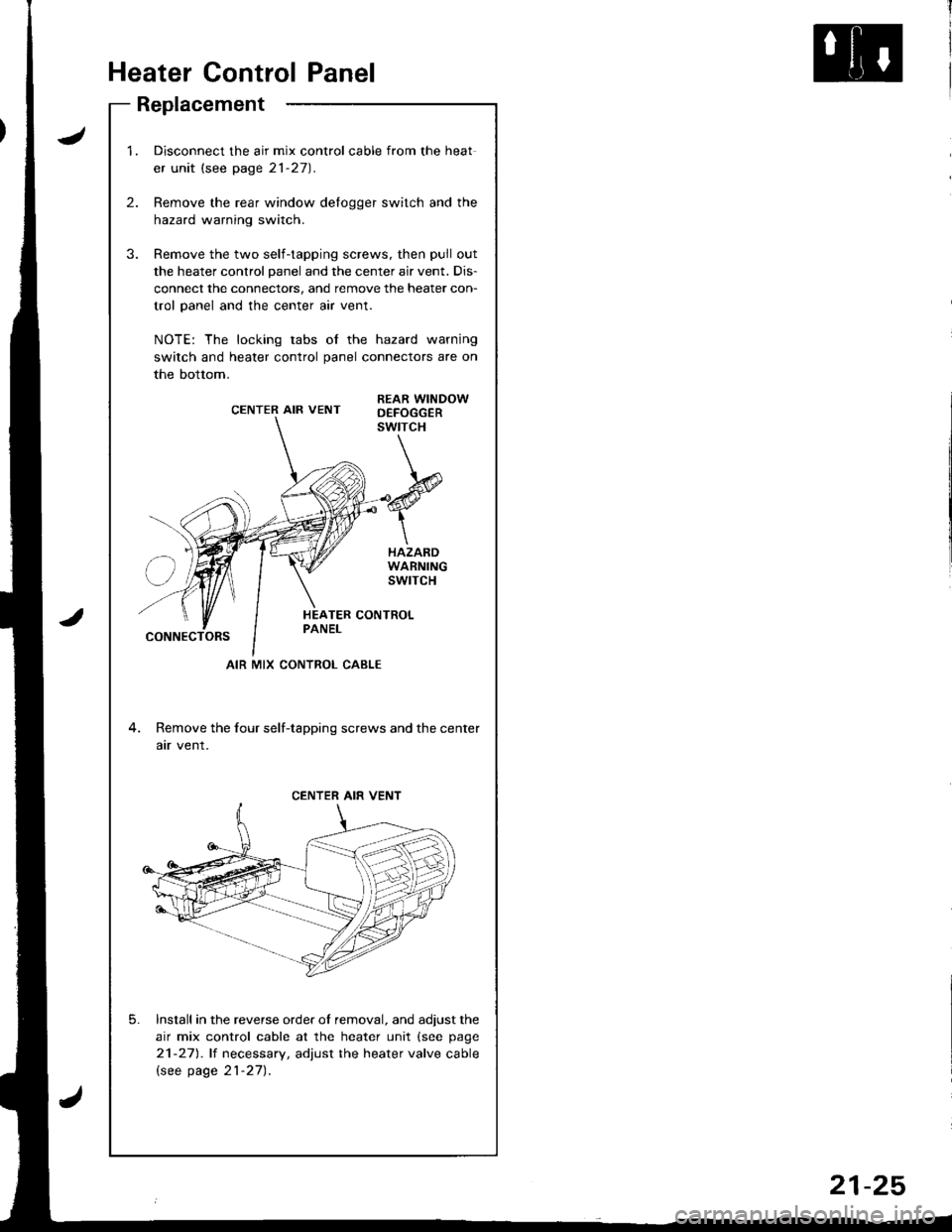
Heater Control Panel
Replacement
J
2.
1.Disconnect the air mix control cable from the heat
er unit (see page 21-27).
Remove the rear window delogger switch and the
hazard warning switch.
Remove the two self-tapping screws, then pull out
the heater control panel and the center air vent. Dis-
connect the connectors, and remove the heater con-
trol panel and the center air vent.
NOTE: The locking tabs of the hazard warning
switch and heater control panel connectors are on
the bottom.
CENTER AIR VENTREAR WINDOWD€FOGGERswtrcH
HAZARDWARNINGswrTcH
CONNECTORS
4. Remove the four self-tapping screws and the center
atr vent.
Install in the reverse order of removal, and adjust the
air mix control cable at the heater unit (see page
21-271.lt necessary, adjust the heater valve cable
lsee page 21-27).
5.
AIR MIX CONTROL CABLE
CENTER AIR VENT
21-25
Page 1024 of 1681
Description
Outline
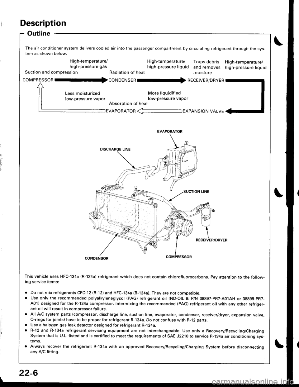
The air conditioner system delivers cooled air into the passenger companment by circulating retrigerant through the sys-
tem as shown below.
High-temperature/ H ig h-tem peratu rel Traps debris High-temperature/high-pressure gas high-pressure liquid and removes high-pressure liquidSuction and compression Radiation of heat moisture
covpnEsson -tl4con oetsen -rr{ REcEIvER/DRvER
More liqu idified
low-pressure vapor
Absorption of heat
Less moisturized
low-pressure vapor
EVAPORATOR -TEXPANS|ON VALVE
EVAPORATOR
CONDENSOR
This vehicle uses HFC-134a (R-134a) refrigerant which does not contain chlorofluorocarbons. Pay attention to the follow-ing service items:
. Do not mix refrigerants CFC-12 (R-12) and HFC-134a (R-134a). They are not compatible.. Use only the recommended polyalkyleneglycol (PAG) refrigerant oil (ND-OIL 8: P/N 38897-PR7-A01AH or 38899-PR7-A01) designed for the R-134a compressor. Intermixing the recommended (PAG) refrigerant oil with any other refriger-ant oil will result in compressor failure.
. All AVC system parts (compressor, discharge line, suction line. evaporator, condenser, receiver/dryer, expansion valve.O-rings for joints) have to be proper for refrigerant R-134a. Do not confuse with R-12 parts.
. Use a halogen gas leak detector designed for refrigerant R-134a.. R-12 and R-134a refrigerant servicing equipment are not interchangeable. Use only a Recovery/Recycling/ChargingSystem that is U.L.-listed and is certified to meet the requirements of SAE J2210 to service R-134a air conditioning sys-tems.
. Always recover the refrigerant R-134a with an approved Recovery/Recycling/Charging System before disconnectingany Ay'C fitting.
22-6
Page 1039 of 1681
A/C Service Tips and Precautions
The air conditioner system uses HFC-134a (R-134a) refrigerant and polyalkyleneglycol {PAG) refrigerant oil (ND-OlL 8: P/N
38897-PR7-A01AH or 38899 - PR7 - A01), which are not compatible with CFC-12 (R-12) refrigerant and mineral oil. Do not
use R-12 refrigerant or mineral oil in this system. and do not attempt to use R-12 servicing equipment; damage to the air
conditioner system or your servicing equipment will result.
Use only service equipment that is U.L.-listed and is certified to meet the requirements of SAE J2210 to remove R-l34a
from the air conditioner system.
CAUTION: Exposure to air conditioner refrigerant and lubricant vapor ot mist can irritate eyos, nose.nd throat, Avoid
breathing th€ air conditionsr rofrigerant 8nd lubricant vapo. or mist.
lf accidental system discharge occurs, ventilate work area before resuming service.
R-134a service equipment or vehicle air conditioner systems should not be pressure tested or leak tested with comp.essed
atf,
@ some mixtures ol air and R-13i[a have been shown to be combustible at olevat6d pre3sures and cln resuh
in fire or explosion causing iniury or property damage. Nover uso compressed air to prossure te3t R-13,[8 service equip-
ment or vehicle air condition6r systems.
Additional health and safety information may be obtained from the refrigerant and lubricant manufacturers,
1. Always disconnect the negative cable from the battery whenever replacing air conditioning parts.
2. Keep moisture and dust out of the system. When disconnecting any lines. plug or cap the Jittings immediately; don't
remove the caps or plugs until just before you reconnect each line.
3. Before connecting any hose or line, apply a few drops of refrigerant oilto the O-ring,
4. When tightening or loosening a fitting, use a second wrench to support the matching fitting.
5. When recovering the system. use a R-134a refrigerant Recovery/Recycling/Charging System; don't release refrigerant
into the atmosphere.
6. Add refrigerant oil after replacing the following parts.
NOTE:
. To avoid contamination, do not return the oil tothe container once dispensed, and never mix itwith other refriger-
ant oils.
.lmmediatelyafterusingtheoil,replacethecaponthecontainerandseal it to avoid moisture absorption.
. Do notspillthe refrigerant oil onthevehicle; it maydamagethe painu itthe refrigerant oil contacts the paint, wash
it off immediately.
Coodansor ..-.-.-............. 25 mt (5/6 ll.oz. 0.9 lmp.oz)
Evaporator ................. ,[0 m/ (1 1/3 fl.oz, 1.4 lmp.ozl
Line or hoss .................. 10 m? {1/3fl.oz, 0.'l lmp.ozl
Receiver/Dryer ............. 10 m/ (1/3 fl.oz, 0.4 lmp.ozl
Leskage repair .............25 m/ {5/6 fl.oZ, 0.9 lmp.oz)
Compreigor .....,......,..Fo1 comprgssor replace-
ment, subtract the volum€ of oil drained from the
removed comprassor lrom l/t{l m[ (1 213 ll.oz, 1,9
imp'ozl, and drain the calculated volume ot oil from
the new compressor: 140 m/ 11 213 ll.oz, 1.9
imp.oz)-Volum€ oI removed comprsssor = Volum€
to drain trom n€w compressor.
NOTE: Even if no oil is drained from the removed
comDressor, don't drain more than 50 m{ {1 2/3
fl.oz. 1.8 lmp.oz) from the new compressor.
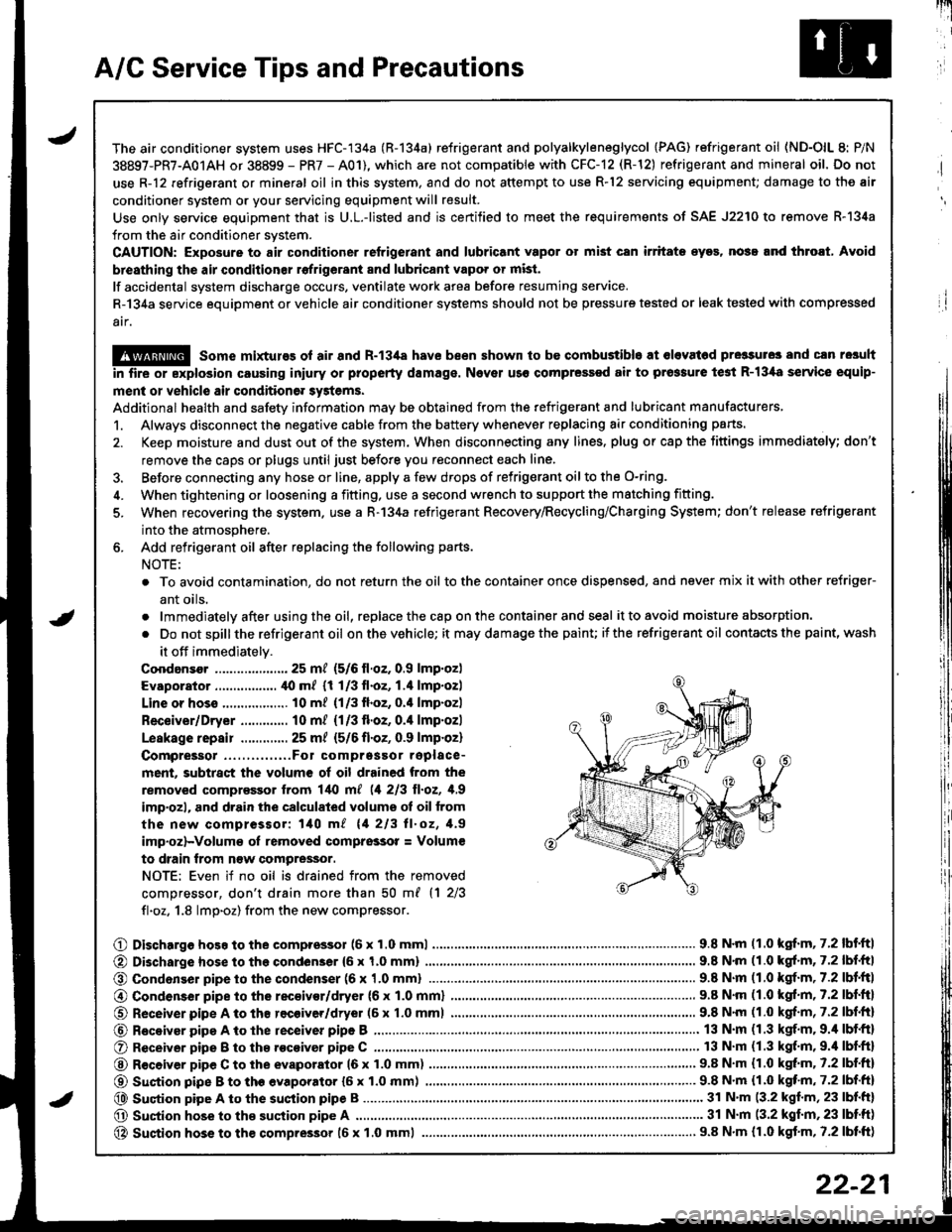
O Dischargo hoso to the compressol (6 x 1.0 mml............................... 9.8 N'm (1.0 kgf.m, 7.2 lbf'ftl
@ Di3charge hose to the condenser {6 x 1,0 mm)
@ Condonser pipe to the condenser (6 x '1.0 mml
9.8 N'm (1.0 kgl.m, 7.2 lbf.ftl
.. 9.8 N.m (1.0 kgf.m,7.2lbl.ltl
@ Condenser pipe to the rec€ivor/dryer (6 x 1.0 mml
O Receiver pipe A to th8 recoiver/dryer (6 x 1.0 mml
@ Receiyar pipe A to lhe receiver pipe B ,...........
O Receiver pipe B to th8 .ocoiver pipe C ............
@ R€ceiver pipe C to the evaporator 16 x 1.0 mm)
@ Suction pipe B to th€ evaporator {6 x 1.0 mm) .......,.
@ Suqtion pipe A to the suction pipe B
O Suction hose to the suction pipe A ...........,.
@ Suction hose to the compressor 16 x 1.0 mml
9.8 N.m (1.0 kgf.m, 7.2 lbf.ftl
9.8 N'm (1.0 kgf.m, 7.2 lbf.fr)
13 N.m (1.3 kgf.m. 9.4 lbf.ft)
13 N.m (1.3 kgf.m,9.'l lbf.ftl
9.8 N.m (1.0 kgt m. 7.2 lbf.ftl
...... 9.8 N.m {1.0 kqf'm, 7.2 lbf.ft)
........ 31 N'm (3.2 kgf.m, 23 lbf.ft)
............ 31 N.m (3.2 kgf.m,23 lbtft)
..................... 9.8 N.m {r.0 kgf.m, 7.2 lbtft)
22-21
Page 1061 of 1681
Troubleshooting
Tips and Precautions (cont'd)
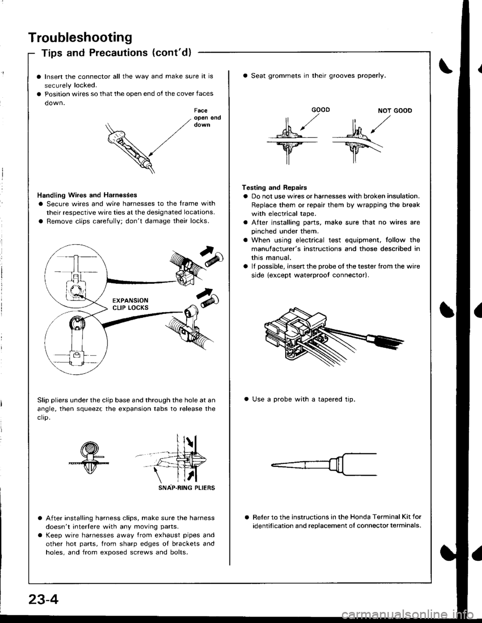
Insert the connector all the way and make sure it is
securely locked.
Position wires so that the open end of the cover faces
down.Faceopen end
V
Handling Wires and Harnesses
I Secure wires and wire harnesses to the frame with
their respective wire ties at the designated locations.
a Remove clips carefully; don't damage their locks.
Slip pliers under the clip base and through the hole at an
angle, then squeez€ the expansion tabs to release the
clro.
sNAP-R|NG PLtERS
After installing harness clips, make sure the harness
doesn't interlere with any moving parts.
Keep wire harnesses away from exhaust pipes and
other hot parts, trom sharp edges ol brackets and
holes, and from exposed screws and bolts.
GOOD NOT GOOD
MA/
lr lr\
Testing and Repairs
a Do not use wires or harnesses with broken insulation.
Replace them or repair them by wrapping the break
with electrical tape.
a Atter installing parts. make sure that no wires are
oinched under them.
a When using electrical test equipment. follow the
manulacturer's instructions and those described in
this manual.
a lI possible, insert the probe of the tester {rom the wire
side {except waterproot connector).
a Seat grommets in their grooves properly.
a Use a probe with a tapered tip.
Reler to the instructions in the Honda Terminal Kit for
identification and replacement oI connector terminals.
23-4
Page 1064 of 1681
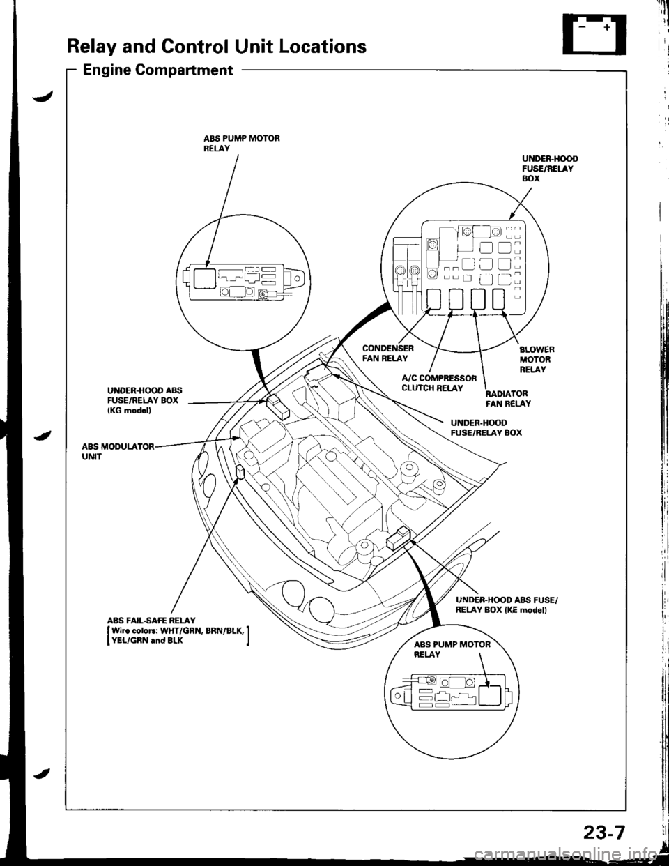
Relay and Control Unit Locations
Engine Compartment
ABS PUMP MOTORRELAY
FAN RELAY
UNDER.HOOD AB{iFUSE/RELAY BOXIKG mod.ll
A/C COMPRESSORCLUTCH RELAYRADIATORFAN BELAY
UNDER.H(X)DFUSE/RELAY BOX
A&S MODULAUNIT
UNDER.HOOD ABII FUSE,/RELAY BOX {KE modoll
----ar:l
--r: u
D
tr
L]
ABS PUMP MOTOR
23-7
Page 1069 of 1681
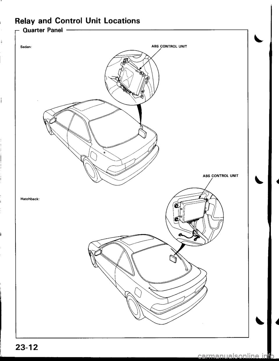
Relay and Control Unit Locations
Ouarter Panel
ABS CONTROL UNIT
23-12
Page 1070 of 1681
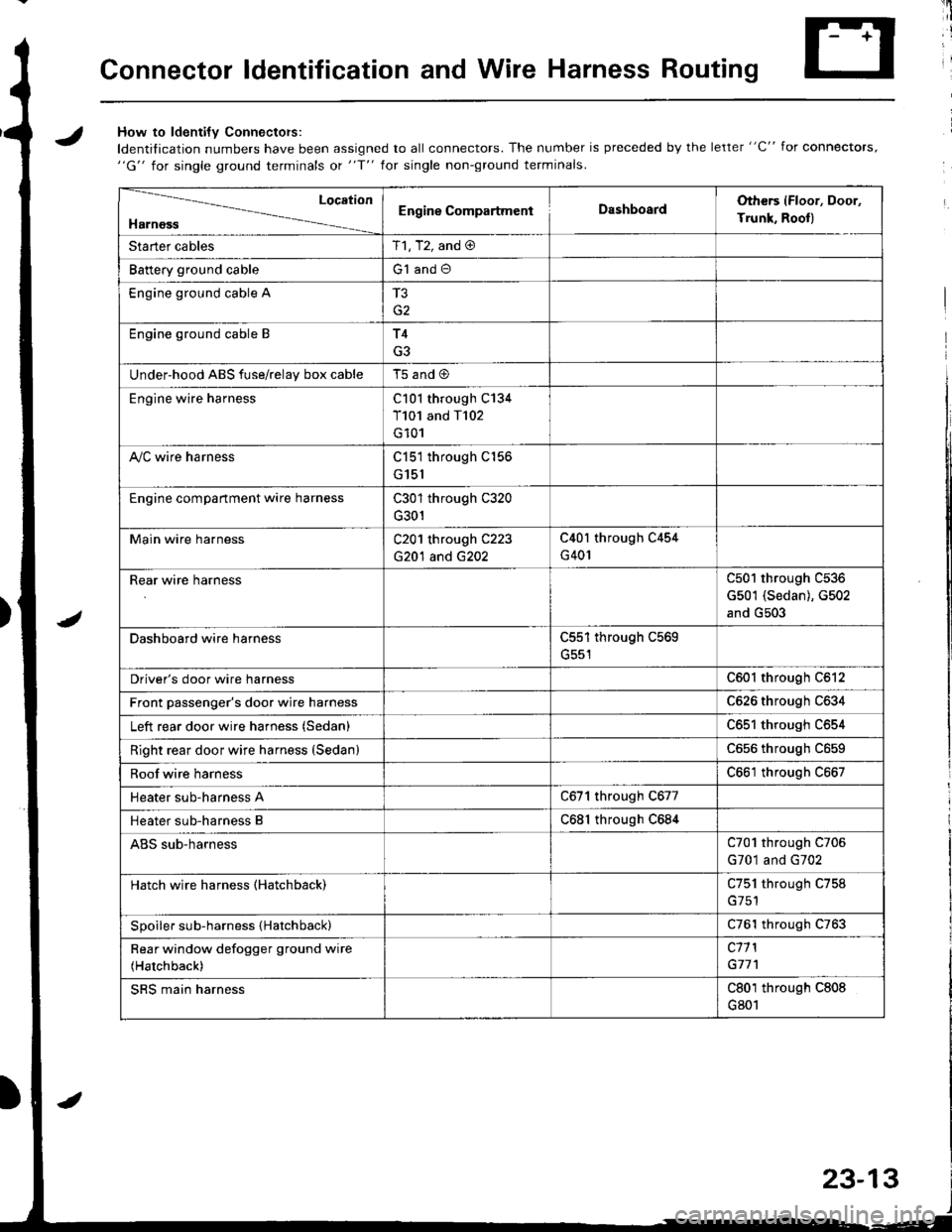
Connector ldentification and Wire Harness Routing
JHow to ldenti{v Connectors:
ldentification numbers have been assigned to all connectors. The number is preceded by the letter "C" for connectors,"G" for single ground terminals ot "f" lor single non-ground terminals.
/
Location
HarnossEngine CompartmentDashboardOthers (Floor, Door,
Trunk. Rooll
Starter cablesT1, T2, and @
Battery ground cableG1 and O
Engine ground cable A
G2
Engine ground cable BT4
G3
Under-hood ABS fuse/relav box cableT5 and @
Engine wire harnessC101 through C134
T101 and T102
G101
A,/C wire harnessC151 through C156
G151
Engine compartment wire harnessC301 through C320
G301
Main wire harnessC201 through C223
G20'l and G202
C40l through C454
G401
Rear wire harnessC501 through C536
G501 (Sedan), G502
and G503
Dashboard wire harnessC551 through C569
G551
Driver's door wire harnessC601 through C612
Front passenger's door wire harnessC626 through C634
Left rear door wire harness (Sedan)C65l through C654
Right rear door wire harness (SedanlC656 throughc659
Roof wire harnessC661 through C667
Heater sub-harness AC671 through C677
Heater sub-harness BC68l through C684
ABS sub-harnessC701 through C706
G701 and G702
Hatch wire harness (Hatchback)C751 through C758
Spoiler sub-harness {Hatchback)C761 through C763
Rear window defogger ground wire
(Hatchback)
c11 l
G77'l
SRS main harnessC801 through C808
G801
23-13
Page 1071 of 1681
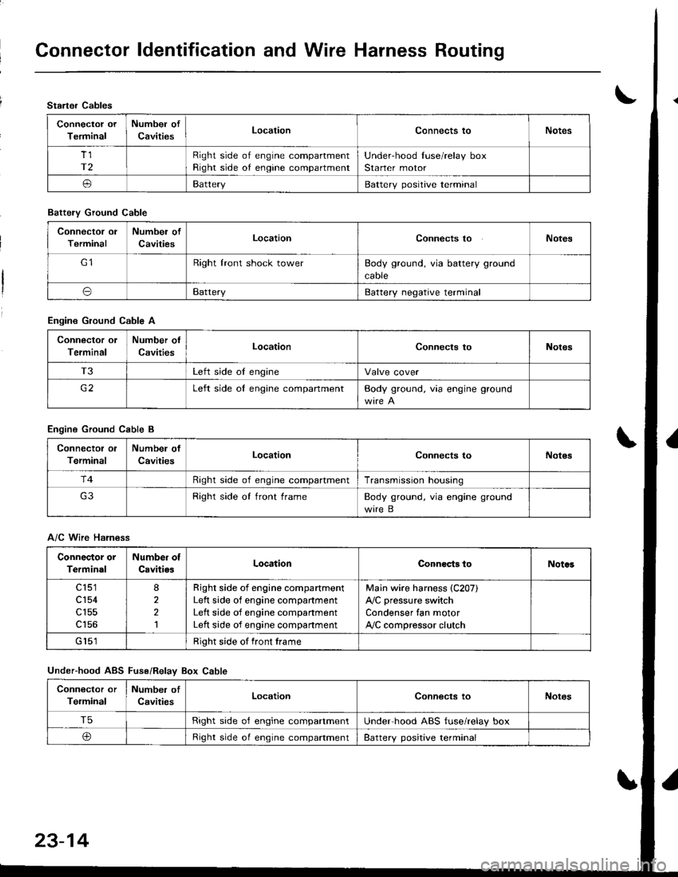
Connector ldentification and Wire Harness Routing
Starter Cables
Connectol ot
Terminal
Numbel of
CavitiesLocationConnects toNotes
Tl
r2
Right side of engine compartment
Right side oI engine compartment
Under-hood Iuse/relay box
Starter motor
oBatteryBattery positive terminal
Battely Ground Cable
Connector ol
Terminal
Numbel of
CavitiesLocationConnects toNotes
Right lront shock towerBody ground, via battery ground
caore
oBatteryBattery negative terminal
Engine Ground Cable A
Connector ol
Terminal
Number ol
CavitiesLocationConnects toNotes
T3Left side of engineValve cover
c2Left side oI engine compartmentBody ground. via engine ground
Engine Ground Cable B
Connector ol
Terminal
Numbel of
CavitiesLocationConnects toNot€s
r4Right side of engine compartmentTransmission housing
Right side of front frameBody ground, via engine ground
wire B
A/C Wire Harness
Connector or
Terminal
Number of
CavitiesLocationConnects toNotos
c 151
cl54
c156
8
2,l
Righr side of engine compartment
Left side of engine companment
Left side of engine compartment
Left side of engine compartment
Main wire harness (C207)
A,/C pressure switch
Condenser fan motor
ly'C compressor clutch
Right side of front frame
Under-hood ABS Fuse/Relav Box Cable
Connector or
Telminal
Number of
CavitiesLocationConnects toNotes
T5Right side o'f engine compartmentUnderhood ABS fuse/relay box
@Right side oI engine compaftmentBattery positive terminal
23-14