1998 HONDA CR-V ECO mode
[x] Cancel search: ECO modePage 520 of 1395
Description
General Operation (cont'dl
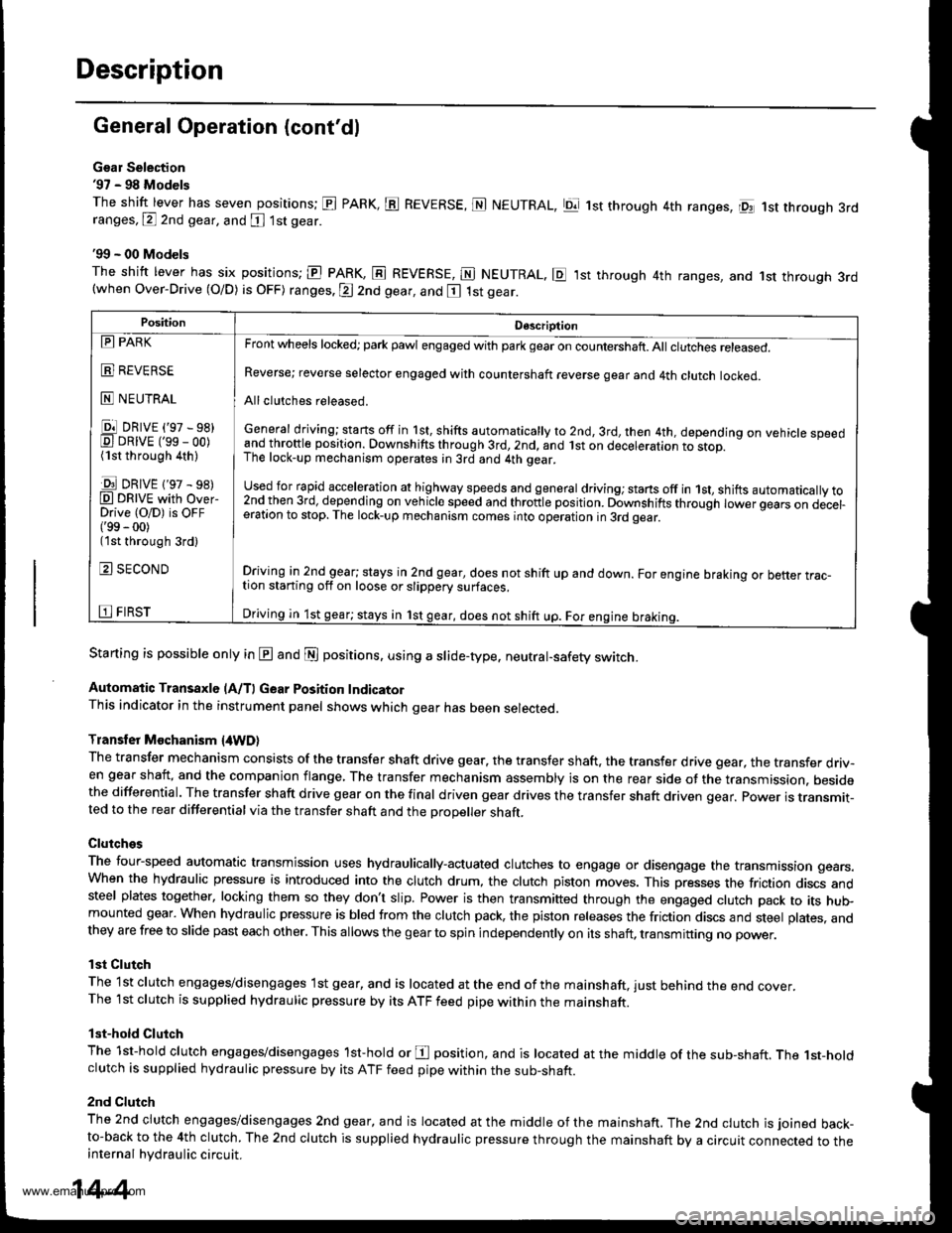
Gsar Selection'97 - 98 Models
The shift lever has seven positions; El PARK, ts REVERSE, N NEUTRAL, Ell 1st through 4th ranges, lpq 1st th.ough 3rdranges, P 2nd gear, and [ 1st gear
'99 - 00 Models
The shitt lever has six positions; El PARK, E REVERSE, E NEUTRAL. E ,lst through 4th ranges, and 1st through 3rd(when Over-Drive (O/D) is OFF) ranges. @ 2nd gear, and E 1st gear.
Starting is possible only in @ and @ positions. using a slide-type. neutral-safety switch.
Automatic Transaxle (A/T) Gear Position IndicatorThis indicator in the instrument panel shows which gear has been selected.
Transler Mochanism {4WD}
The transfer mechanism consists of the transfer shaft drive gear. the transfer shaft. the transfer drive gear, the transfer driv-en gear shaft, and the companion flange, The transfer mechanism assembly is on the rear side ot the transmission. besidethe differential. The transfer shaft drive gear on the final driven gear drives the transfer shaft driven qear. power is transmit-ted to the rear differential via the transfer shaft and the Drooeller shaft.
Clutches
The four-speed automatic transmission uses hydraulically-actuated clutches to engage or disengage the transmission gears.When the hydraulic pressure is introduced into the clutch drum, the clutch piston moves. This presses the friction discs andsteel plates together, locking them so they don't slip. Power is then transmifted through the engaged clutch pack to its hu$mounted gear. When hydraulic pressure is bled from the clutch pack, the piston releases the friction discs and steel plates, andthey are free to slide past each other. This allows the gearto spin independently on its shaft, transmitting no power.
lst Clutch
The 1st clutch engages/disengages lst gear, and is located at the end ofthe mainshaft, just behind the end cover.The 1st clutch is supplied hydraulic pressure by its ATF feed pipe within the mainshaft.
lst-hold Clutch
The 1st-hold clutch engages/disengages 1st-hold or E position, and is located at the middle of the sub-shaft. The 1st-holdclutch is supplied hydraulic pressure by its ATF feed pipe within the sub-shaft.
2nd Clutch
The znd ciutch engages/disengages 2nd gear, and is located at the middle of the mainshaft. The 2nd clutch is joined back-to-back to the 4th clutch. The 2nd clutch is supplied hydraulic pressure through the mainshaft by a circuit connected to theinternal hydraulic circuit.
PositionDescription
Reverse; reverse selector engaged with countershaft reverse gear and 4th clutch locked.
Allclutches released.
General driving; starts off in 1st, shifts automatically to 2nd, 3rd, then 4th, depending on vehicle speedand throftle position. Downshifts through 3rd,2nd, and lst on deceleration to stop.The lock-up mechanism operates;n 3rd and 4th gear.
used for rapid €cceleration at highway speeds and general driving; stans off in 1st, shifts automatically to2nd_then 3rd, dejending on vehicle speed and throttle position. Downshifts through lower gears on decel-eration to stop. The lock-up mechanism comes into operation in 3rd gear.
Driving in 2nd_gear; stays in 2nd gear, does not shift up and down. For engine braking or better trac_tion starting off on loose or slippery surfaces.
Driving in 1st gear; stays in 1st gear, does not shift up. For engine braking.
tll PARK
t!!l l|EvEn>E
E NEUTRAL
Ell DRrvE ('97 - sB)E DRrvE ('ss - oo)(1st through 4th )
E DRrvE {'97 - s8)O DRTVE with over-Drive (O/D) is OFF('99 - 00)(1st through 3rd)
E SECOND
E FIRST
14-4
www.emanualpro.com
Page 536 of 1395
Description
Electronic Control System (cont'd)
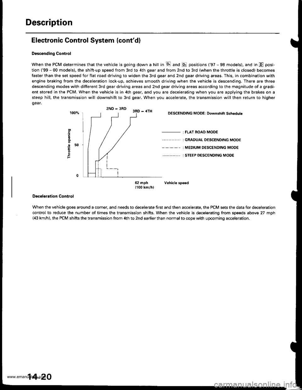
Descending Control
When the PCM determines that the vehicle is going down a hill in E and @ positions ('97 - 98 models). and in @ posi-
tion {'99 - 00 models), the shitt-up speed from 3rd to 4th gear and from 2nd to 3rd (when the throttle is closed) becomes
faster than the set speed for flat road driving to widen the 3rd gear and 2nd gear driving areas. This, in combination with
engine braking from the deceleration lock-up, achieves smooth driving when the vehicle is descending. There are three
descending modes with different 3rd gear driving areas and 2nd gear driving areas according to the magnitude of a gradi-
ent stored in the PCM. When the vehicle is in 4th gear, and you are decelerating when you are applying the brakes on a
steep hill, the transmission will downshift to 3rd gear, When you accelerate, the transmission will then return to higher
gear.
2ND - 3RD 3RD - 4TH
o50
F
DESCENDING MODE: Downshift Schodule
- : FLAT ROAD MODE
----'-----' I GRADUAL DESCENDING MODE
- - - - - : MEDIUM OESC€NOING MODE
. . ... : STEEP DESCENDING MODE
62 mph Vehicle sp€ed1100 km/hl
Deceleration Control
When the vehicle goes around a corner, and needs to decelerate first and then accelerate, the PCM sets the data for deceleration
control to reduce the number of times the transmission shifts. When the vehicle is decelerating from speeds above 27 mph(4i| km,ih), the PCM shifts the transmission from 4th to 2nd earlier than normal to cope with upcoming acceleration,
14-20
www.emanualpro.com
Page 546 of 1395
Description
Hydraulic Flow (cont'dl
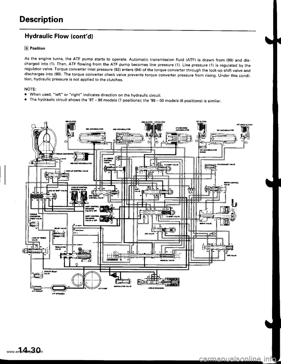
lll Position
As the engine turns, the ATF pump starts to operate. Automatic transmission fluid (ATF) is drawn from (99) and dis-charged into (1). Then, ATF flowing from the ATF pump becomes line pressure ('l). Line pressure (1) js regulated by theregulator valve. Torque converter inlet pressure {92) enters (94) of the torque conveTter through the lock-up shift valve anddischarges into (90) The torque converter check valve prevents torque converter pressure from rising. Under this condi-tion, hydraulic pressure is not applied to the clutches.
NOTE;
. When used. "|eft" o. "right" indicates direction on the hvdraulic circutt.. The hydraulic circuit shows the '97 - 98 models {7 positions}; the '99 - 00 models (6 positions) is similar.
'lF'.j.l
14-30
www.emanualpro.com
Page 547 of 1395
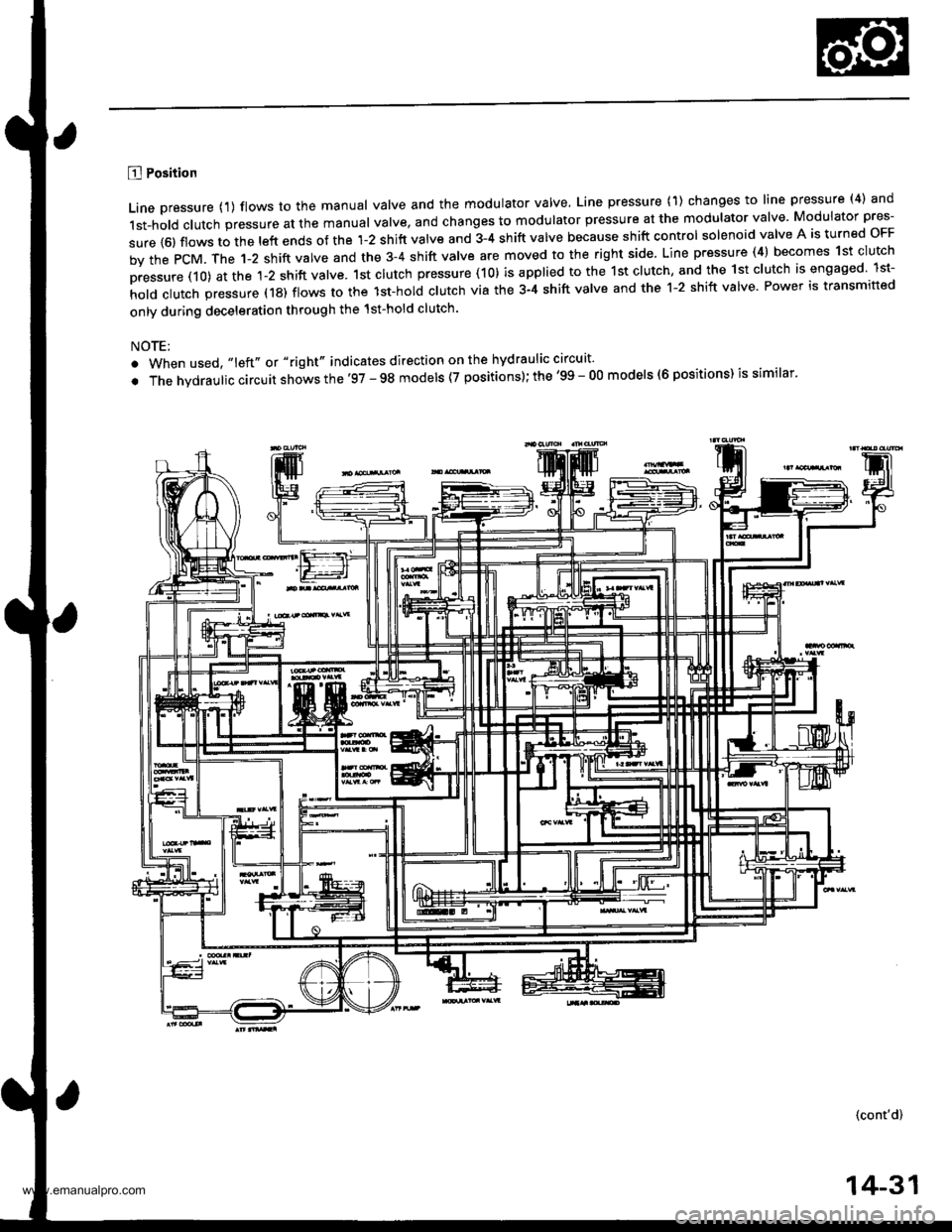
B Position
Line pressure {1) flows to the manual valve and the modulator valve, Line pressure (1) changes to line pressure (4) and
1st-hold clutch pressure at the manual valve, and changes to modulator pressure at the modulator valve Modulator pres-
sure {6) flows to the left ends of the 1-2 shift valve and 3-4 shift valve because shift control solenoid valve A is turned oFF
by the PcM. The 1-2 shift valve and the 3-4 shift valve are moved to the right side. Line pressure (4) becomes 1st clutch
pressure (10) at the 1-2 shift valve. 1st clutch pressure (10) is applied to the 1st clutch, and the 1st clutch is engaged lst-
hold clutch pressure (18) flows to the lst-hol; clutch via the 3-4 shift valve and the 1-2 shift valve Power is transmitted
only during deceleration through the 1st-hold clutch.
NOTE:
. When used, "left" or "right" indicates direction on the hydraulic circuit'
. The hvdraulic circuit shows the'97 - 98 models (7 positions); the '99 - O0 models (6 positions) is similar'
(cont'd)
14-31
www.emanualpro.com
Page 551 of 1395
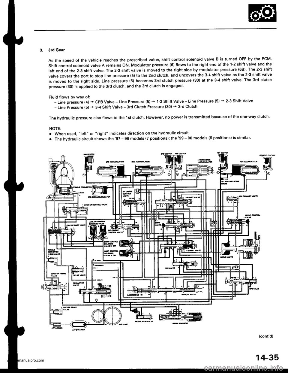
3. 3rd Gear
As the speed of the vehicle reaches the prescribed value. shift control solenoid valve B is turned OFF by the PCM.
Shift control solenoid valve A remains ON. Modulator pressure (6) flows to the right end of the 1-2 shift valve and the
left end of the 2-3 shift valve. The 2-3 shift valve is moved to the right side by modulator pressure (68) The 2-3 shift
valve covers the port to stop line prsssure (5) to the 2nd clutch. and uncovers the 3-4 shift valve as the 2-3 shift valve
is moved to the right side, Line pressure (5) becomes 3rd clutch pressure (30) at the 3-4 shift valve. The 3rd clutch
pressure (30) is applied to the 3rd clutch, and the 3rd clutch is engaged.
Fluid flows by way of:- Line pressure (4) - CPB Valve - Line Pressure (5) * 1-2 Shift Vaiv€ - Line Pressure (5) * 2-3 Shift Valve
- Line Pressure (5) * 3-4 Shift Valve - 3rd Clutch Pressure (30) * 3rd Clutch
The hvdraulic Dressure also flows to the 1st clutch. However, no power is trsnsmitted because of the one-way clutch.
NOTE:
. When used, "|eft" or "right" indicates direction on ths hydraulic circuit.
. The hvdraulic circuit shows the '97 - 98 models (7 positions); the'99 - 00 models (6 positions) is similar.
(cont'd)
14-35
www.emanualpro.com
Page 552 of 1395
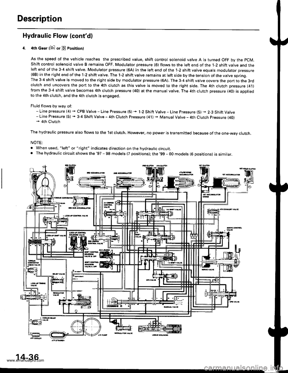
Description
Hydraulic Flow (cont'd)
4th Gear llQ! or E Posirion)
As the speed of the vehicle reaches the prescribed value. shift control solenoid valve A is turned OFF by the pCM,
Shift control solenoid valve B remains OFF. Modulator pressure (6) flows to the left end of the 1-2 shift valve and theleft end of the 3-4 shift valve. Modulator pressure (64) in the left end of the 1-2 shift valve equals modulator pressure(68) in the right end of the 1-2 shift valve. The 1-2 shift valve remains at left side by the tension of the valve spring.The 3-4 shift valve is moved to the right side by modulator pressure (6A). The 3-4 shift valve covers the pon to the 3rdclutch and uncovers the port to the 4th clutch as this valve is moved to the right side, The 4th clutch pressure (41)from the 3-4 shift valve becomes 4th clutch pressure (40) at the manual valve. The 4th clutch pressure (40) is appliedto the 4th clutch, and the 4th clutch is engaged.
Fluid flows by way of:- Line pressure (4) + CPB Valve - Line Pressure (5) + l-2 Shift Valve - Line Pressure {5) * 2-3 Shift Valve- Line Pressure (5) + 3-4 Shift Valve - 4th Clutch Pressure (41) + Manual Valve - 4th Clutch Pressure (40)+ 4th Clutch
The hydraulic pressure also flows to the lst clutch. However, no power is transmitted because of the one-wav clutch.
NOTE:
. When used, "lelt" or " tight" indicates direction on the hydraulic circuit.. The hydrau lic circuit shows the '97 - 98 models (7 positions); the '99 - 0O models (6 oositions) issimilar.
14-36
www.emanualpro.com
Page 562 of 1395
![HONDA CR-V 1998 RD1-RD3 / 1.G Workshop Manual
PCM Circuit Diagram (A/T Control System)
97 Model
UNDER.I]OOD FUSAFELAY BOXEATTEFY
_YEL_
T-l ,
TT-l
t_-:
G101
Fr-r.04
P- r.-or..u L_a TMEALOC(BrK€ru -<< calTFoL
P_ *+rr
F- onmrxCFUISECONTFOLUNITf HONDA CR-V 1998 RD1-RD3 / 1.G Workshop Manual
PCM Circuit Diagram (A/T Control System)
97 Model
UNDER.I]OOD FUSAFELAY BOXEATTEFY
_YEL_
T-l ,
TT-l
t_-:
G101
Fr-r.04
P- r.-or..u L_a TMEALOC(BrK€ru -<< calTFoL
P_ *+rr
F- onmrxCFUISECONTFOLUNITf](/manual-img/13/5778/w960_5778-561.png)
PCM Circuit Diagram (A/T Control System)
'97 Model
UNDER.I]OOD FUSAFELAY BOXEATTEFY
_YEL_
T-l ,
TT-l
t_-:
G101
'Fr-r.04
P- r.-or..u L_a TMEALOC(BrK€ru -<< calTFoL
P_ *+rr
F- onmrxCFUISECONTFOLUNITf-"".>
| ["'"]
I l,[-l
III ;,
F_ pw
P_ eLu
F-- enN
UNDER DASN
M 25(7.54)
IGNITONSWITCH UNDEF OASNFUSAFELAYSOX
oowEa-qar. cor.lFo- MooLrE rpcMr F &*1 r*--'l_____O_=_ATP IO! ,ATP . ATD , A-P , A-P , A-PNP lrNo lR 101 103 12 ll
Ar'TGEAR POS]TIONswtcN
14-46
www.emanualpro.com
Page 570 of 1395

PCM Terminal Voltage/Measuring Conditions
A/T Control System -'98 - 00 Models
The PCM terminal voltage and measuring conditions are shown for the connector terminals that are related to the A"/T con-
trol system. The other PCM terminal voltage and measuring conditions are described in section 11.
FCM Connector Terminal Localions
NOTE: 819 and C3 terminalsare applied to'99 - 00 models.
o (16Pt
T6rminal NumberSignalDescriptionMeasuring Conditions/Terminal Voltage
A5CRSDownshift signal input from
cruise control unit
When cruise control is used; Pulsing signal
A10scsTiming and adjustment service
check signal (5 V from PCM)
With ignition switch ON (ll) and service check
connector open:5 V
With ignition switch ON (ll) and service check
connector jumped with special tool: 0 V
A14('98 model)
D4 INDD4 indicator light control
{Voltage from PCM turns D4 light
oN)
When ignition switch is first turned ON (ll):
Battery voltage for two seconds
In E position: Battery voltage
A14
('99 - 00 models)
D INDD indicator light control(Voltage from PCM turns D light
oN)
When ignition switch is first turned ON (ll):
Baftery voltage for two seconds
ln E position: Battery voltage
428ILUInterlock control(Voltage from PCM)
When ignition switch ON {ll), brake pedal
depressed, and accelerator pedal released:
Battery voltage
A.32STOP SWBrake switch signal inputBrake pedal pressed; Battery voltage
Brake pedal released: 0 V
FCM CONNECTOR B I25P}
Terminal NumberSignalDescriptionMeasuring Conditions/Terminal Voltage
B1IGPlPower supply circuit from main
relay via under-hood Fuse 44
With ignition switch ON {ll): Battery voltage
With ignition switch OFF: 0 V
82PG1Ground (G101)
B8LSMLinear solenoid power supply
negative electrode
IG P2Power supply circuit from main
relay
With ignition switch ON (ll): Baftery voltage
With ignition switch OFF: 0 V
810PG2Ground (G101)
B17Linear solenoid power supply
positive electrode
With ignition switch ON (ll): Pulsing signal
819
('99 - 00 models)
O/D INDOver-Drive (O/D) OFF indicator
light control
When ignition switch is first turned ON (ll):
0 V for two seconds
O/D OFF indicator light ON:0 V
O/D OFF indicator light OFF: Battery voltage
s20Ground (G101)
B�21VBUBack-up power supply(under-hood Fuse 47)
Always battery voltage
B�22LG2Ground (G101)
14-54
www.emanualpro.com