1998 HONDA CR-V Troubleshooting ignition switch
[x] Cancel search: Troubleshooting ignition switchPage 648 of 1395
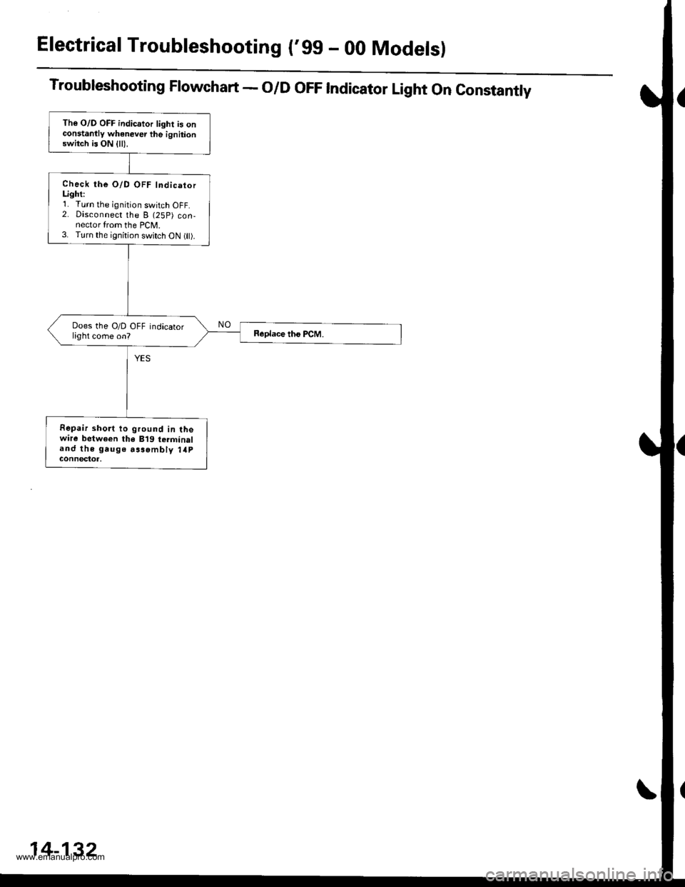
Electrical Troubleshooting ('gg - 00 Modelsl
Troubleshooting Flowchart - O/D OFF Indicator Light On Constantly
The O/D OFF indicator light is onconstanllv whenever the ignitionswitch is ON {ll),
Check the O/D OFF IndicatorLighti'1. Turn the ignition switch OFF.2. Disconnect the B (25P) con-nector from the PCM.3. Turn the ignition switch oN flt).
Does the O/D OFF indicatorlight come on?
Fepair short to ground in lhewire between the B'19 terminaland the gauge aasombly 14pGOnnectot,
14-132
www.emanualpro.com
Page 649 of 1395
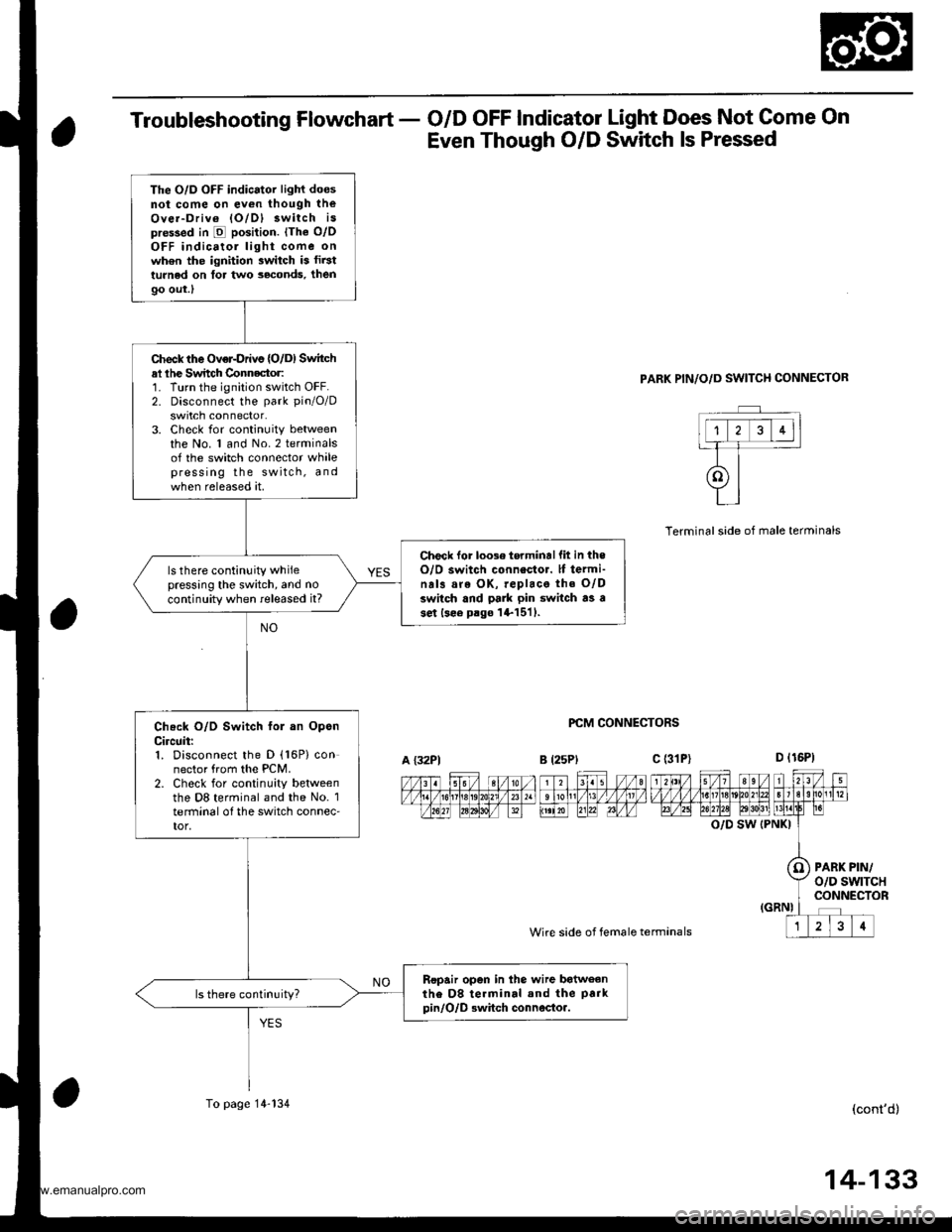
Troubleshooting Flowchart - O/D OFF Indicator Light Does Not Come On
Even Though O/D Switch ls Pressed
PARK PIN/O/D SWITCH CONNECTOR
PCM CONNECTORS
Wire side of female termanals
Terminalside of male terminals
O/D SW (PNKI
PARK PIN/o/D swtTcHCONNECTOR
(cont'd)
The O/D OFF indicator light doesnot come on ev€n though theOver-Driv6 lO/Dl 3witch ispre$ed in E position. lThe o/oOFF indicatol light come onwh6n the ignition switch is fir3tturned on tor two seconds, then
9o out.l
Check the Over-Drivs {O/D) Switchal lhe Switch Connector:1. Turn the ignition switch OFF.2. Disconnect the park pin/O/D
swrtch connector.3. Check for continuity betweenthe No. 1 and No.2 terminalsof the switch connector whalepress ing the switch, andwhen released at.
Check lor loose torminallit in theO/O switch connestor. lf termi-na13 are OK, replace the O/Dswitch and pa]k pin switch as ase.t lsee p.go l+1511.
ls there continuity whilepressing the switch, and no
continuity when released it?
Check O/D Switch fol an OpsnCircuit:1. Disconnect the D (16P) connector from the PCM.2. Check for continuity betweenthe D8 terminal and the No. 1terminal o{ the switch connec'tor,
Ropair open in the wire batweanthe D8 te.minal and the park
pin/O/D Bwhch connocto..
A {32P1B l25Plc (31P)
To page 14-134
14-133
www.emanualpro.com
Page 788 of 1395
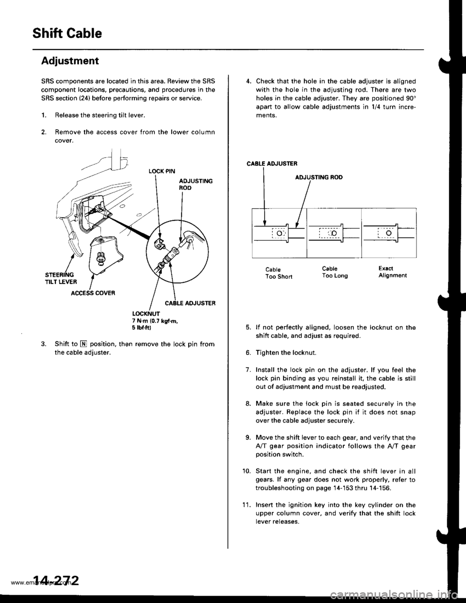
Shift Gable
Adjustment
SRS components are located in this area. Review the SRS
component locations, precautions, and procedures in the
SRS section (241 before performing repairs or service.
1. Release the steering tilt lever.
2. Remove the access cover from the lower column
cover.
LOCK PIN
AOJUSTINGnoo
ADJUSTER
7 N.m (0.7 kg{.m,5 tbf.ft)
3. Shift to E position. then remove the lock pin from
the cable adjuster.
K\ffi
/* 1 6-,>
snenrftc YTILT LEVER IACCESS COVER
14-272
'l 1.
4. Check that the hole in the cable adjuster is aligned
with the hole in the adjusting rod. There are two
holes in the cable adjuster. They are positioned 90"
apart to allow cable adjustments ln l/4 turn incre-
ments.
CABLE ADJUSTER
CablsToo Short
lf not perfectly aligned, loosen the locknut on the
shitt cable. and adjust as required.
Tighten the locknut.
Install the lock pin on the adjuster. lf you feel the
lock pin binding as you reinstall it, the cable is still
out of adjustment and must be readjusted.
Make sure the lock pin is seated securely in the
adjuster. Replace the lock pin if it does not snap
over the cable adjuster securely.
Move the shift lever to each gear, and verify that the
A/T gear position indicator follows the A"/T gear
position switch.
Start the engine, and check the shift lever in all
gears. lf any gear does not work properly, refer to
troubleshooting on page 14-'153 thru 14-156.
Insert the ignition key into the key cylinder on the
upper column cover, and verify that the shift lock
tever reteases.
CableToo LongExactAlignment
7.
a
10.
www.emanualpro.com
Page 846 of 1395

Steering
Special Toofs ............. 17-2
Component Locations
Index ................ ....... 17-3
Troubleshooting
General Troubleshooting ................ 1 7-4
Noise and Vibration ......................... 17-8
Fluid Leaks ............. 17-10
Inspection and Adiustment
Steering Operation .......................... 17-12
Power Assist Check
With Vehicle Parked ....................
Steering Linkage and Gearbox .......
Pump Belt
Rack Guide Adjustment ...................
Fluid Rep|acement ...................,,.,....
Pump Pressure Check .................,,...
*Steering Wheel
Removal ................. 17-18
*Steering Column
Removal/lnstallation ................ ....... 17 -2O
lnspection .............. 17-21
Steering Lock Replacement ............ 17 -22
Power Steering Hoses, Lines
Ffuid Leakage Inspection ................. 17 -23
Repfacement .......... 17-23
Power Steering Pump
Repfacement .......... 17-24
Disassembly ...........17-25
fnspection .............. 17-26
Reassembly ............ 17-28
Power Steering Gearbox
Removal ................. 17-31
Disassembly ........... 17-34
Reassembly ............ 17-40
Ball Joint Boot Replacement .......... 17-50
Installation ............. 17-51
17-12
17-13
17-14
l7-15
17-15
17-16
Disassembly/Reassembly............... 17-18
4'%/b.......... -r'-7--a/
SUPPLEN\EN AL RES\RA(N SYSTES{ (SRS\
This model has an SRS which includes a driver's airbag in the steering wheel hub. a passenger's airbag in the dashboardabove the glove box ('97 - 00 models), and seat belt tensioners in the seat belt retractors ('98 - 00 models). Informationnecessary to safely service the SRS is included in this Service Manual. ltems marked with an asterisk (*) on the contentspage include, or are located near, SBS components. Servicing. disassembling or replacing these items will require specialprecautions and tools, and should only be done by an authorized Honda oearer.
To avoid rendering the SRS inoperative, which could lead to peFonal iniury or death in the event of a sevore trontalcollision. allSRS service work must be performod by an authorized Honda dealer.lmproper service procedurgs, including incorrect removal and installalion of the SRS, could lead to personal iniurycaused by unintontional deployment of th€ airbags {'97 - 00 models), and seat belt tensioners ('98 - 00 modelsl.Do not bump the SRS unit. Otherwise, the system may lail in case ot a collision, or the airbags may deploy when theignition switch is ON (lll.
SRS electrical wiring harnesses are identitied by yellow colof coding. Ralated components are located in the steeringcolumn, front console, dashboard, dashboard lower panel, and in the dashboard above the glove box. Do not use elec-trical test equipment on these cilcuits,
www.emanualpro.com
Page 959 of 1395

Troubleshooting Precautions
ABS lndicalor
1 lf the system is oK, the ABS indicator goes off two seconds after turning the ignition switch oN 1l) wathout staningthe engine, and then comes on again and goes off after two seconds. This occurs because the ABS control unit isturned on by the lG2 power source.2. The ABS indicator comes on when the ABS control unit detects a problem in the system. However, even thouoh thesystem is operating properly, the ABs indicator will come on too, under the following conditions:. Signal disturbance
. Wheel spin
. Only drive wheels rotate. Battery voltage fluctuates
To determine the actual cause of the problem, question the customer about the problem, taking these conditions intoconsideration:
3 When a problem is detected and the ABS indicator comes on, the indicator can stay on until the ignition switch isturned OFF, or it can automatically go off, depending on the mode.. Indicator stays on untilthe ignition switch is turned off: When the system is in the system down mode.. Indicator automatically goes off: When the system is in the control inhibition mode.4 The ABS indicator stays on when the system is reactivated without erasing the DTC, but it goes off after starting thevehicle.
When the wheel sensor system is faulty and the ABS indicator comes on. the algorithm of the system automatically turnsoff the ABS indicator after the wheel speed signal returns to the normal speed. Also, when the DTc is erased, the cpu isreset and the ABS indicator goes off when the system checked out normal by the initial diagnosis.Therefore, test-drive the vehicle after servicing the wheel sensor system. and be sure that the ABS indicator does notcome on.
5 When the ABS control unit outputs battery voltage to the gauge assembly, the ABS indicator ooes off.
Diagnostic Trouble Code (DTCI
1. The diagnostic trouble code (DTc) is memorized when a problem is detected and the ABS indicator does not go off,or when the ABS indicator comes on.The DTc is not memorized when the ABS indicator comes on unress the cpu is activated,2 The memory can hold any number of DTCs. However, when the same DTc is detected twice or more, the tater one iswritten over the old one.
Therefore, when the same problem is detected repeatedly, it is recorded as one DTC.3. The DTCs are indicated in the order of ascending number, not in the order they occur.4. The DTCS are memorized in the EEPROM (non-volatile memorv).Therefore, the memorized DTcs cannot be canceled by disconnecting the battery. perform the specified procedures toerase the DTCS.
Self-diagnosis
1. Self-diagnosis can be classified into these four categories:' Initial diagnosis: Performed right after the eng ine starts and untir theABS indicator goes off.. Except ABS control: Performed when the ABS is not functioning.. During ABS control: Performed when the ABS is functioning.. During warning: Performed when the ABS indicator is ON.2. The system performs the fo|owing contrors when a probrem is detected by the serf-diagnosis:. ABS indicator ON. Memorv of DTC. Mode changetothe "system down mode,, or the ,,control inhibition mode,,.
MODEABS INDICATORMAIN
RELAY
SOLENOID
VALVECPURestart conditionDTC
SYSTEM
DOWNONNo
operation
Drive
inhibitionOperation*rlgnition
switchoFF - ON l)Memory
CONTROL
INHIBITIONONNo
operal|on
Drive
inhibitionOperationAutomaticlMemory
*1: Except CPU failure
19-36
www.emanualpro.com
Page 963 of 1395
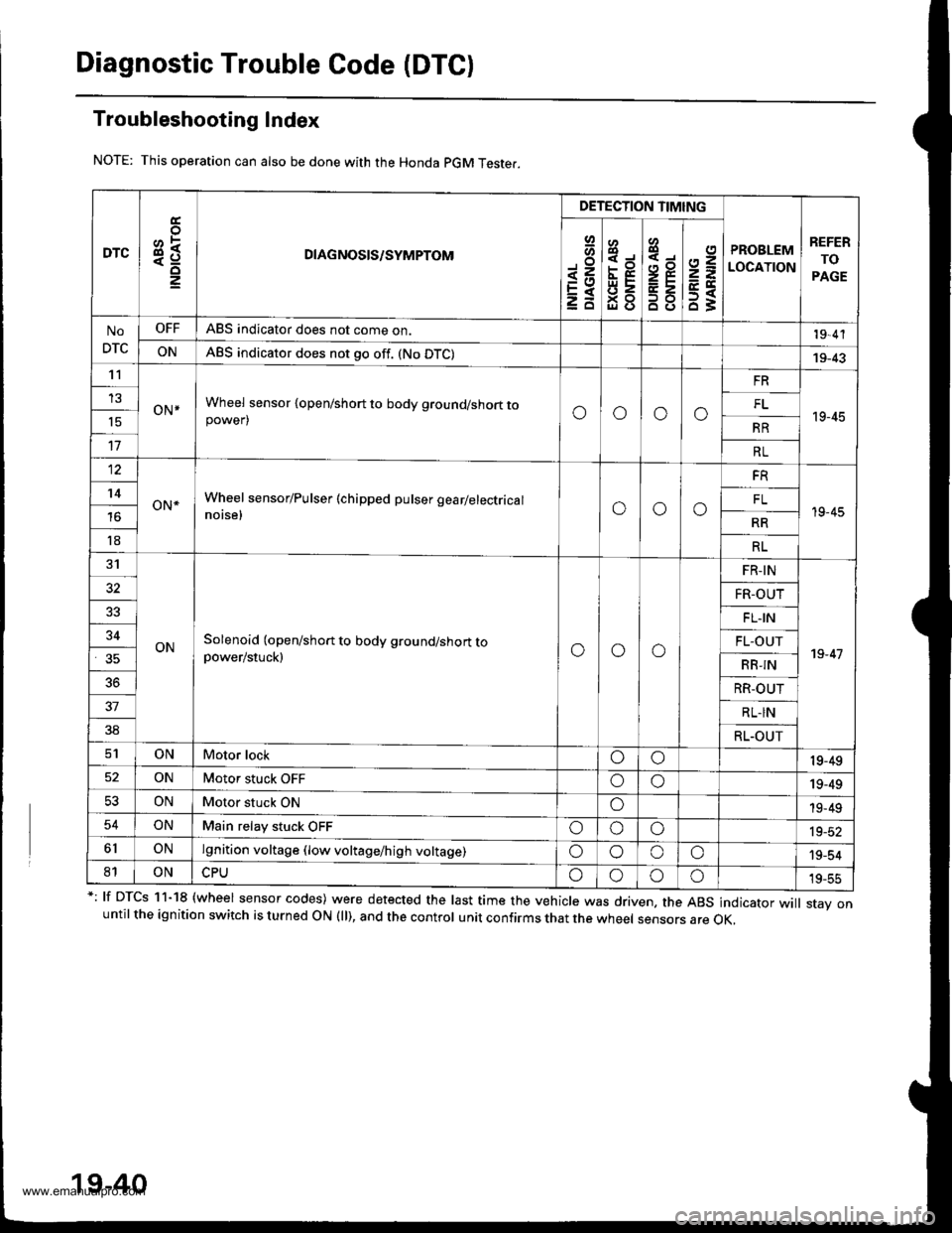
Diagnostic Trouble Code (DTC)
Troubleshooting Index
This operation can also be done with the Honda pGM Teste..
*: lf DTcs 11-18 {wheel sensor codes) were detected the last time the vehicle was driven, the ABs indicator wi
stav onuntil the ignition switch is turned ON (ll), and the control unit confirms that the wheel sensors are OK,
19-40
DTC3R
DETECTION TIMING
PROBLEM
LOCATION
REFER
TO
PAGE
Io
<=EXzd
8
93gl (J
4,,to
B8
2=
ET63
No
DTC
OFFABS indicator does not come on.19,4'l
ONABS indicator does not go off. (No DTC)19-43't1
oN*Wheel sensor {open/short to body ground/short topower)oooo
FR
19-45
13FL't5RR
17RL
12
oN*Wheel sensor/Pulser (chipped pulser gearlelectrical
notse,ooo
FR
19-45
't4FL
RR
18RL
31
ONSolenoid (open/short to body ground/short topower/stuck)ooo
FR-IN
19-47
32FR-OUT
FL.IN
34FL-OUT
RB-IN
36RR-OUT
37RL-IN
38RL.OUT
ONMotor lockoo19-49
ONMotor stuck OFFoo19-49
53ONMotor stuck ONo19-49
54ONMain relay stuck OFFoooia_at
6lONlgnition voltage (low voltage/high voltage)oooo'19-54
81ONoooo19-55
www.emanualpro.com
Page 964 of 1395
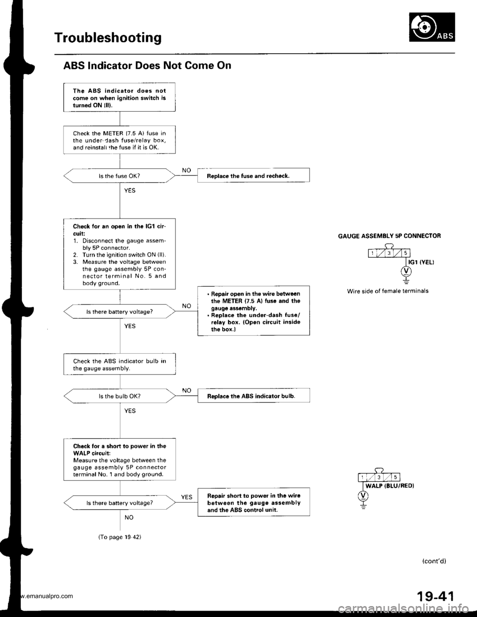
Troubleshooting
ABS lndicator Does Not Come On
The ABS indicator does notcome on when ignition switch isturnod ON lll).
check the METER {7.5 A} fuse inthe underCash fuse/relay box,and reinstaltthe fuse if it is OK.
Check for an open in the lcl ch-cuil:1. Disconnect the gauge assem-bly 5P connector.2. Turn the ignition switch ON (ll).
3. Measure the voltage betweenthe gauge assembly 5P con-nector terminal No. 5 andbody ground.
. Repair open in the wire betweenlhe METER {7.5 A) luse and thogauge assembly.. Reolece the under-dash fuse/relay box. (Opon circuit insidethe box.)
ls there battery voltage?
Check the ABS indicator bulb inthe gauge assembly.
Replace the ABS indicator bulb.
Check for a short to power in theWALP circuit:Measure the voltage between thegauge assembly 5P connectorterminal No. 1 and body ground.
Sepair short to power in the witeb€tween the gaug€ assemblyand the ABS control unil.ls there battery voltageT
Reolace the tuse and recheck.
(To page 19 42)
GAUGE ASSEMBLY 5P CONNECTOR
Wire side of female terminals
(cont'd)
19-41
www.emanualpro.com
Page 965 of 1395
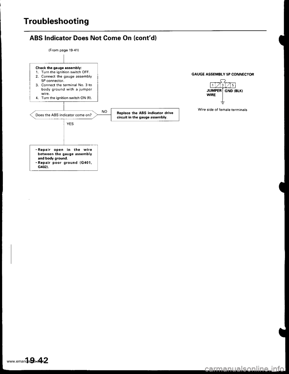
Troubleshooting
ABS Indicator Does Not Come On (cont'd)
(From page 19'41)
GAUG€ ASSEMBLY 5P CONNECTOR
---g-l1 t/l3_l/ | 5 |JUMPER I GND IBLK}wrBE IL
Wire side of female terminals
Check the gruge essembly:1. Turn the ignition switch OFF.2. Connect the gauge assembly5P connector,3. Connect the terminal No. 3 tobody ground with a jumper
4. Turn the ignition switch ON (ll).
Reolace the ABS indicator drivecircuit in the gaug€ ass€mbly.Does the ABS indicator come on?
.Repair open in the wirebetween the gauge assemblyand body ground.. Repair poor ground {G401,c102l-
19-42
www.emanualpro.com