Page 967 of 1395
Troubleshooting
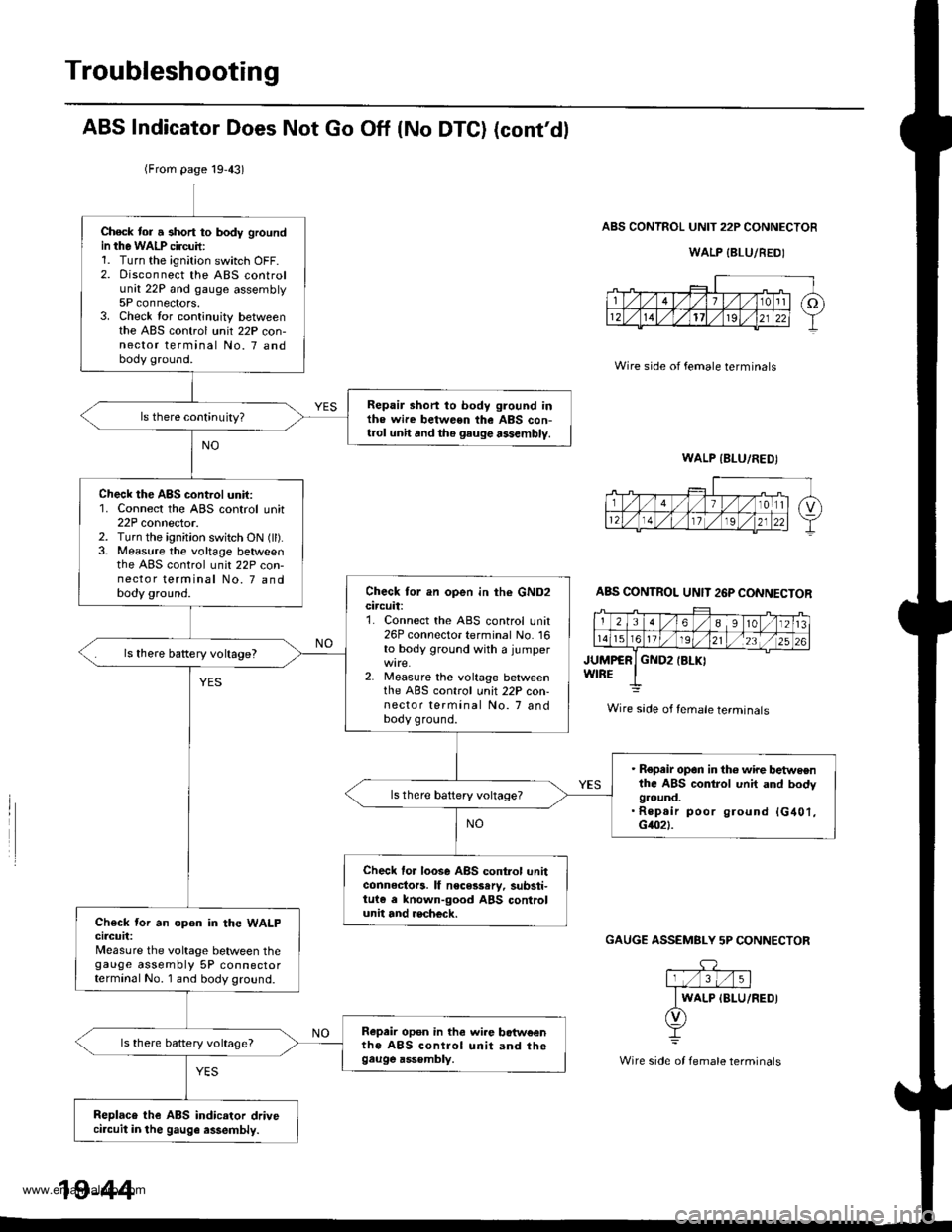
ABS Indicator Does Not Go Off (No DTC) (cont'dl
ABS CONTROL UNIT 22P CONNECTOR
WALP {BLU/REDI
Wire side of female terminals
JUMPCRWIREGND2IBLKI
GAUGE ASSEMBLY 5P CONNECTOF
(From page 19,43)
Check tor a short to body groundin the WALP circuil:1. Turn the ignition switch OFF.2. Disconnect the ABS controlunit 22P and gauge assembly5P connectors.3. Check lor continuity betweenthe ABS control unit 22P con-nector terminal No. 7 andbody ground.
Repair short to body ground inthe wire between the ABS con-t.ol unh and the gauge assembly.
Check the ABS control unit:1. Connect the ABS control unit22P connector.2. Turn the ignition switch ON (ll).3. Measure the voltage betweenthe ABS control unit 22P con-nector terminal No. 7 andbody ground.Check tor an open in the GND2circuit:1. Connect the ABS control unit26P connecto. terminal No. 16to body ground with a jumper
2. Measure the voltage betweenthe ABS control unit 22P con-nector terminal No. 7 andbody ground.
ls there battery voltage?
. Repeir op6n in th6 wire ttetweenthe ABS control unit and bodyground.. Rep.ir poor ground {G401,G4021.
Check lor loose ABS control unhconnectors. lf necesssry, substi-tuie e lnown-good ABS controlunit and recheck.Check tor an open in the WALPcircuit:Measure the voltage between thegauge assembly 5P connectorterminal No. 1 and body ground.
Repair op6n in the wi.e botw€enthe ABS control unit and th€gau9e ass€mbly.
ls there battery voltage?
Replaco the ABS indicator drivecircuit in the gauge assembly.
ABS CONTROL UNIT 26P CONNECTOR
Wire sade of female terminals
WALP IBLU/FEDI
19-44
www.emanualpro.com
Page 973 of 1395

Troubleshooting
DTC 51 - 53: ABS Pump Motor (cont'dl
(From page 19 49)
UND€R-HOOO ABSFUSE/REI-AY BOX
MOTOR +B IREDIMOTOR GND IBLKI
TERMINAL TERMINAL
PUMP MOTOR CONNECTOB
Fr MOTOR +B {WHTI12 lF-(v)vI
Terminal side of female terminals
Terminalside ofmaleterminals
ABS CONTROL UNIT 22P CONNECTOR
JUMPER WIRE
Wire side of female terminals
Chock the pump motor ci.cuit:1. Remove the pump motor relay.2. Turn the ignition switch ON {ll).3. Connect the pump motor relayconnector +B and MOTOR ter-minals with a jumpor wire fora moment,
Check for an open in the pump
motor +B circuit:1. Turn the ignition switch OFF.2. Disconnect the pump motor
3. Turn the ignition switch ON (ll).
4. Connect the pump motor relayconnector +B and MOTOR terminals with a iumper wire.5. Measure the voltage beaveenthe pump motor connectorterminal No. l and bodygrou nd.
Does the pump motor operate?
Bepair opon in the wire botweenthe under-hood ABS fuse/relavbor and the pump motor.ls there battery voltage?
Check the pump motor opera-tion:Connect the battery (+)terminal tothe pump motor connector termi-nal No. 1, and the (-) terminal tothe terminal No. 2 for a moment.
Reolace the modulator unit.
lFaulty pump moto.lDoes the pump motor operate?
Ch6ck for a short to body groundin the PMR circuit:1. Turn the ignition switch OFF.2. Disconnect the ABS controlunit 22P connector.3. Check tor continuity betweenterminal No. 19 and bodyground.
Repair open in the wire bstweenthe pump motor and body ground,
or poo. ground {G3511.
Repair short to body ground inthe wir6 botween the under-hood ABS tuse/rclay box and th€ABS contlol unit.
{To page 19-51)
www.emanualpro.com
Page 975 of 1395
![HONDA CR-V 1998 RD1-RD3 / 1.G Workshop Manual
Troubleshooting
DTG 54: Main Relay
IWHT/GRNI
AAS CONTROL UNIT 26P CONNECTON
Wire side of female terminals
ABS COf{TROL UN]T 22P CONNECTOR
PCOMIGRN/WHTIscoM{BLK/WHTI
Wire side of female terminals
- Wi HONDA CR-V 1998 RD1-RD3 / 1.G Workshop Manual
Troubleshooting
DTG 54: Main Relay
IWHT/GRNI
AAS CONTROL UNIT 26P CONNECTON
Wire side of female terminals
ABS COf{TROL UN]T 22P CONNECTOR
PCOMIGRN/WHTIscoM{BLK/WHTI
Wire side of female terminals
- Wi](/manual-img/13/5778/w960_5778-974.png)
Troubleshooting
DTG 54: Main Relay
IWHT/GRNI
AAS CONTROL UNIT 26P CONNECTON
Wire side of female terminals
ABS COf{TROL UN]T 22P CONNECTOR
PCOMIGRN/WHTIscoM{BLK/WHTI
Wire side of female terminals
- With the ignition switch ON(lll, the ABS indicator doesnot go off.- With the SCS service connec-tor connected {see page 19-381,DTC 54 is indicatod.
Check the ABS +B 120 A) fuse inthe under-hood ABS luse/relaybox, and reinstall the fuse if it isoK.
FeDlace the tu3e and recheck.
Ch€ck tor an open in the 81, 82circuit:Measure the voltage betweenbody ground and the ABS controlunit 26P connector terminal No. 14and No. 15 individually.
Repair open in the wiro bstweonth6 ABS conirol unit and theunder-hood ABS fuse/rolay box,
ls there battery voltage?
Check for a short to body groundin the PMR circuit:L Turn the ignition switch OFF.2. Remove the pump motor relay.3. Disconnect the ABS controlunit 22P connector.4. Check lor continuity betweenterminal No. 19 and bodygrouno.
Repair short to body ground inthe wire betweon the under-hood ABS lGe/r.lay box and theABS control unit.
Check for a short to body groundin the PCOM, SCOM cilcuit:1. Disconnect the ABS controlunit 26P connector.2. Check tor continuity betweenbody ground and the ABS con-trol unit 26P terminals No- 1and No.2 individually.
. R€pair short to body ground inth€ P1COM circuit wire betweenthe ABS control unit and theund6r-hood ABS tuse/r6layoox.. R6p.ir short to body ground inthe PCOM or SCOM circuit wirebetweon th6 ABS control unitand lhe mod!lator unit.. R.Dlece tho modulrtor unit.(Short circuit inside the unitl
ls there continuity?
(To page 19-53)
www.emanualpro.com
Page 1104 of 1395
Troubleshooting
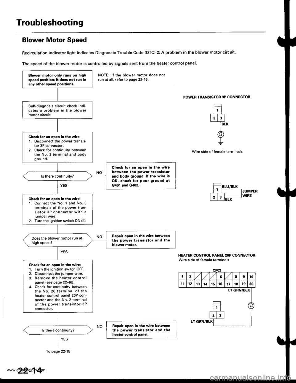
Blower Motor Speed
Recirculation indicator light indicates Diagnostic Trouble Code (DTC) 2: A problem in the blower motor circuit
The speed of the blower motor is controlled by signals sent from the heater control panel
POWER TRANSISTOR 3P CONNECTOR
1
2)3
f
BLK
Wire side of female terminals
JUMPERWIRE
HEATER CONIROL PANEL 2OP CONNECTORWire side oI fgmale t€rminals
12,/1,/68I10
't112131ia't51611181920
LI GRN/BLK
o
LT GBN/BLK
Blower motol only runs on highspood position; h does not run inany othe. speod positions.
Self-diagnosis circuit check indi-cates a problem in the blowermotor circuit,
Chack lor.n open in the wire:1. Disconnect the power transis-tor 3P connector.2. Check for continuity betweenthe No.3 terminal and bodygro(1nd.
Chock for.n op.n in thc wirobotween ihe powa. transistorrnd body ground, It tho wir. is
OK, check for poor ground atG,O1 .nd G4o2.
ls there continuity?
Chsck for an opon in the wire:'1. Connect the No. 1 and No. 3t€rminals of the power tran-sistor 3P connector with ajumper ware.2. Turn the ignition switch ON {ll).
Repair op6n in the wiro betwoontho Dower transi3tol and theblowor motor.
Check tor an open in tho wire:1. Turn the ignition switch OFF.2. Disconnect the iumper wire.3. Remove the heater controlpanel (see page 22-46).4. Check for continuity botweenthe No. 20 terminal of theheater control panel 20P con-nector and the No.2 terminalof the power transistor 3Pconnectof,
R€pair opon in tho wire betwoenth6 oowor ttan3i3tor and th6hoatar control oanel.
NOTE: lf the blower motor doesrun at all, refer to page 22-16.
10 page 22-15
22-14
www.emanualpro.com
Page 1106 of 1395
Troubleshooting
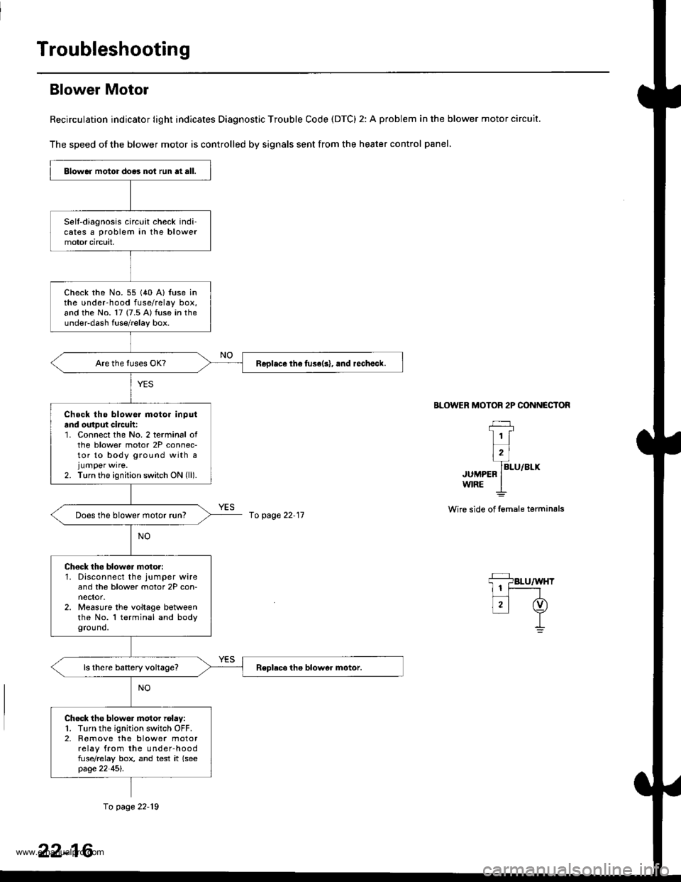
Blower Motor
Recirculation indicator light indicates Diagnostic Trouble Code (DTC) 2: A problem in the blower motor circuit.
The speed of the blower motor is controlled by signals sent from the heater control panel,
BLOWER MOTOR 2P CONNECTOR
JUMPEFw|RE
Wire side of lemale terminals
Blower motor do.3 not run at all.
Selt-diagnosis circuit check indi-cates a problem in the blowermotor circuit,
check rhe No. 55 (40 A) {use inthe under-hood fuse/relay box,and the No. 17 (7.5 A) fuse in theunder-dash fuse/relay box.
Replace th6 fuse(s), and rechalck.
Check tho blowe. motor inputand output cilcuh:1. Connect the No. 2 terminal ofthe blower motor 2P connec-tor to body ground with ajumper wrre.2. Turn the ignition switch ON (ll).
Does the blower motor run?
Chock the blower moto.:1. Disconnect the jumper wireand the blower motor 2P con-nector.2. Measure the voltage betweenthe No. l terminal and bodygrou nd.
Check tho blower motor rolay:1. Turn the ignition switch OFF.2. Romove the blower motorrelay from the under-hoodfuse/relay box, and test it (seepage 22 45l'.
fo page 22-11
fo page 22-19
22-16
www.emanualpro.com
Page 1112 of 1395
Troubleshooting
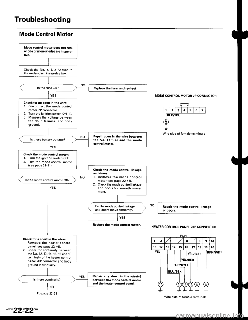
Mode Control Motor
NO
MODE CONTROL MOTOR 7P CONNECTOR
13I5
BLK/YEL
Wire side of female terminals
HEATER CONTROL PANEL 2OP CONNECTOR
BRN/WHT
Wire side of female terminals
Mode control motol does not run.or ono or more modes are inoD€aa-
Check the No. 17 {7.5 A) Iuse inthe under-dash fuse/relay box.
Replace the tus€, snd iecheck.
Chock tor an open in th€ wi.6:1. Disconnect the mode controlmotor 7P connector.2. Turn the ignition switch ON (ll).3. Measure the voltage betweenthe No. l terminal and bodyground.
Repair opon in the wire betwoontho No. 17 luse and tho modecontrol motor.
Check the mode control motor:1. Turn the ignition switch OFF.2. Test the mode control motorGee page 22 41') .
Chock th€ mode cont.ol link.geand doors:1. Remove the mode controlmotor (see page 22-41).2. Check the mode control linkageand doors for smooth move-ment,
ls lhe mode control motor OK?
Do the mode control linkageand doors move smoothly?
Replece the inod6 control motor.
Chock for s shon in the wir€s:1. Remove the heater controlpanel (see page 22'46).2. Check for continuity betweenthe No. 12, 13, 14, 15, 16 and 19terminals ol the heater controlpanel 20P connector and bodyground individuaily.
Repair any short in the wire(slbetween the mode control rnotoaand the h6ater control Danel.
ls there continuity?
2l,/1,/8I10
111213ta151617r81320
BLU
[E!r!
YEL/RED
Ii
To page 22-23
www.emanualpro.com
Page 1114 of 1395
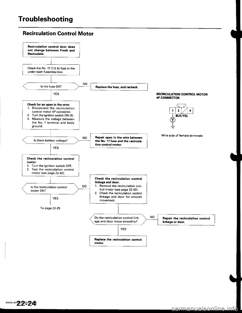
Troubleshooting
Recirculation Gontrol Motor
YES
To page 22-25
REORCULATION CONTROL MOTOR,rP CONNESTOR
q?- T--- V-l
l1, lrl/l1lI BI.IUYEL(v)
+
Wire side of female terminals
Rocirculation control door do6snoi chango botw€en Fresh andReci.culate.
Check the No. 17 {7.5 A)tuse in theunder-dash f use/relay box.
Roplace the fu36, and rechock.
Check for .n open in the wire:1. Disconnect the recirculationcontrol motor 4P connector.2. Turn the ignition switch ON (ll).3. Measure the voltage betlveenthe No. l terminal and bodyground.
Repair op6n in the wire bdtweenthe No. 17 fuse and thc recircule-tion control motor.
Check the rocirculation controlmoior:1. Turn the ignition switch OFF.2. Test the recirculation controlmotor (see page 22-42).
Chock ths r.circulation controllinkag. end doori1. Remove the recirculation con-trol motor (see page 22,42).2. Check the recirculation controllinkage and door for smooth
Do the recirculation control linkage and door move smoothly?Boprir the recirculrtion controllinkag. or dooJ,
www.emanualpro.com
Page 1118 of 1395
Troubleshooting
Radiator Fan (cont'dl
From page 22-26
RADIATOR FAN RELAY 4P SOCKET
BLK/YEL
1
2
a
Chock for an open in the wire:'1. Disconnect the jurnper wire.2. Turn the ignition switch ON (ll).3. lleasure the voltage betweenthe No.4terrninal of the radia-tor fan relay 4P socket andbody ground.
R€pair open in th6 wire botwoonthe No. 17 fuso and the radiatolfan .elsy.
ls there battery voltage?
Rep.ir open in the GRN wirebotw€en lhe radiator tan relayand the PCM/ECM.
22-28
www.emanualpro.com