Page 443 of 1395

Transfer Assembly
lnspection
@ Make sure tifts, iacks, and satety stands
are placed properly (see section 1).
L Raise the front of the vehicle, and support it with
safety stands (see section 1).
2. Set the parking brake, and block both rear wheels
securely.
3. Shift to neutral oosition.
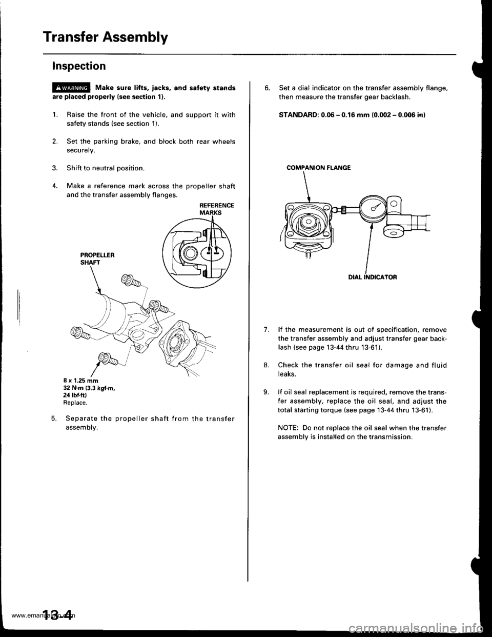
4. Make a reference mark across the DroDeller shaft
and the transfer assembly flanges,
REFERENCE
8 x 1.25 mm32 N.m (3.3 kg{.m.24 rbf.ftlReplace.
Separate the propeller shaft from the transfer
assemDty.
5.
13-4
6. Set a dial indicator on the transfer assembly flange,
then measure the transfer gear backlash.
STANDARD: 0.06 - 0.16 mm (0.002 - 0.006 in)
COMPAf{ION FI-ANGE
1.lf the measurement is out of specification, remove
the transfer assembly and adjust transfer gear back-
lash (see page 13-44 thru '13-61).
Check the transfer oil seal for damage and fluid
teaKs.
lf oil seal replacement is required, remove the trans-
fer assembly, replace the oil seal, and adjust the
total starting torque (see page 13-44 thru 13-61).
NOTE: Do not replace the oil seal when the transfer
assembly is installed on the transmission.
www.emanualpro.com
Page 451 of 1395

Transmission Assembly
lllustrated Index
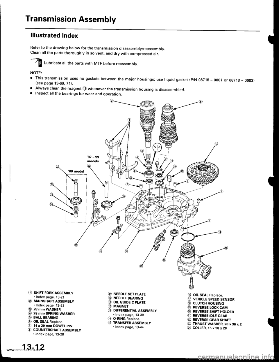
Refer to the drawing below for the transmission disassembly/reassembly.Clean all the pans thoroughly in solvent, and drv with comoressed air.
I LuUri""r" utt the parts with MTF before reassembly.
NOTE:
t This transmission uses no gaskets between the major housings; use liquid gasket (p/N 0g718 - 0001 or oE7l8 - 0003)(see page 13-69, 71).. Always clean the magnet @ whenever the transmissjon housing is disassembled.. Inspect all the bearings for wear and operation.
C) sHrFr FoRK ASSEMBLY.Index page, l3-21(a MAINSHAFT ASSEMBLY.Index page, 13-23(9 28 mm WASHER€) 28 mm SPRTNG WASHERO BALL BEARINGa6) OIL SEAL ReDlace.(D 14 x 20 mm DOWEL ptN
G) couNTERSHAFT ASSEMBLY.lndex page, 13-28
NEEDLE SET PLATENEEDLE BEARINGOIL GUIOE C PLATEMAGNETDIFFERENTIAL ASSEMBLY.lndex page, 13-38O-nlNG Beplace.TRANSFER ASSEMBLY.Index page, '13,44
OIL SEAL Replace.VEHICLE SPEED SENSORCLUTCH HOUSINGREVERSE LOCK CAMREVEESE SHIFT HOLDERREVERSE IDLE GEARREVERSE GEAR SHAFTTHRUST WASHER,20 x 36 x 2COLLER, 15 x 20 x 20
aol
@o@@
(D
i9
@@@(9
@@@e3@
13-12
www.emanualpro.com
Page 452 of 1395
C) TRANSMISSION HANGER
O INTERLOCK BOLT
O 32 mm SEALING BOLT
@ STEEL BALL {5/16 in.)
€) SPRING 26.1 mm {1.03 in.l
@ wasHER Replace.
O sET BALL scREw
@ WASHER Replace.
€) FLANGE BOLT
@ oll SEAL Replace.
@ DRAIN PLUG
@ WASHER Replace.
@ FILLER PLUG
@ WASHER Replace.
(9 10 x 12 mm DOWEL PIN(D SPRING 25.6 mm 11.01 in.l
€' THRUST WASHER
@} SHIFT ARM C(3 CONICAL SPRING WASHER
@ SPECTAL BOLT
8] SHIFT ARM COVER
@ OIL SEAL Replace.
€! SHIFT LEVER
@I BREATHER CAP(2! SHIFT ARM SHAFT ASSEMBLY
@ SPRING PIN Replace.O SELECT ARM
€!} THRUST WASHER
@ sTH/REVERSE SELECTRETURN SPRING
@ SELECT RETURN SPRING
€) OIL GUTTER PLATE
@ 78 mm SHIM
@ OIL GUIOE M PLATE
@ SELECT SPRING BOLT
@ OIL SEAL Replace.
@ SELECT LEVER
O BACK.UP LIGHT SWITCH
@ WASHER Replace.OO TRANSMISSION HOUSING
13-13
www.emanualpro.com
Page 455 of 1395
Transmission Assembly
Disassembly (cont'dl
14. Remove the oil gutter plate, 78 mm shim, and oilguide M plate.
OIL GUIDE M PLATE
15. Remove the select spring bolt.
OIL GUTTER PLATE
SELECT SPRING BOLT
13-16
18. Remove the oil seal.
16.Remove the spring pin using the pin punch and apair of diagonal cutters.
PIN PUNCH, 5.0 mm
17. Remove the select lever, springs, washer, and selectarm.
SEL€CT LEVER
{
V
OIL SEALReplace.
THRUST WASHER
Replace.
SELECT ARM
www.emanualpro.com
Page 457 of 1395

Shift Arm Cover/Shift Arm Shaft Assembly
Disassembly/Reassembly
Shift Arm Cover Ass€mbly
1. Remove the breather cap and set ball screw, washer,
spring. and steel ball.
BREATHER CAP
SPRINGL,25.6 mm (1.01 in.l
T BALL SCREW22 N.m 12.2 kgtm, 16lbf.ftl
Remove the special bolt and conical spring washers.
SHIFTARMCOVER
THRUST WASHER
SHIFI ARM C
WASHER 8x1.0mft
SHIFT LEVER
29 N.m 13.0 kg{.m,z2 tbt.ftl
arm C, and thrustRemove the shift lever, shift
washer from the shift arm cover.
Remove the oil seal.
NOTE: lnstall the thrust washer
face toward shift arm cover.
STEEL BALLD. 5/16 in,
13-18
with the alloy sur-
3. Install in the reverse order of removal.
5. Install the oil seal in to the shift arm cover usino thesDecialtools.
HANOLE07749 - 0010000
ATTACHMENT,32x35mm077a6 - 0010100
OIL SEALReplace.
6. Reassemble the shift arm cover in the reve.se order
of disassembly.
Shift Arm Shaft Assembly
1. Remove the special bolts and conical spring wash-
ers.
SPCCIAL BOLT8x1.0mm29 N.m (3.0 kgf.m,SHIFTARMA 22IbI.ftICONICAL SPRING
SHIFT ARM SHAFT
SPECIAL BOLT8x1.0mm29 N.m {3.0 kgf.m, 22 lbtft}
2. Remove the interlock, shift
from the shift arm shaft.
SPRINGWASHER
arm A, and shift arm B
www.emanualpro.com
Page 479 of 1395

Differential
Bearing Outer Race Replacement
Note these items:
. The bearing outer race and tapered roller bearingshould be replaced as a set.. lnspect and adjust the tapered roller bearing preload
whenever the tapered roller bearing is replaced.
'1. Remove the oil seals from the transmission housingand clutch housing (see page j3-43).
2. Drive the bearing outer race and thrust shim out ofthe transmission housing, or remove the bearingouter race and 75 mm shim from the clutch housingby heating the clutch housing to about 212"F(100"C) with a heat gun. Do not reuse the thrustshim if the outer race was driven out.
TRANSMISSIONHOUSING:
ATTACHMENT52x55mm07746 - 0010400
THRUST SHIM
BEARINGOUTER RACE
CLUTCHHOUSING:
13-40
4, lnstallthe oil seal (see page 13-43).
3. Install the thrust shim or 75 mm shim and the bear-ing outer race in the transmission housing andclutch housing using the special tools.
Note these items during bearing replacement:. Install the bearing outer race squarely.. Check that there is no clearance between thebearing outer race, thrust shim or 75 mm shimand housing.
TRANSMISSIONHOUSING:
HANDI-E07749 - 00 xxto
ATTACHMENT,62x68mm077ir6 - 0010500
BEARINGOUIER RACETHRUST SHIM
CLUTCHHOUSING:HANDLE07749 - 001tXX)o
ATTACHMENT.72xt5mm07745 - 00106{x)
OUTER RACE
75 mm SHIM
www.emanualpro.com
Page 482 of 1395
Oil Seal Replacement
Transmission Housing:
1. Remove the oil seal from the transmission housing
2.lnstall the new oil seal into the transmission hous-
ing using the special tools.
NOTE: Install oil seal up to i0.5 mm (10.02 jn) from
transmission housing end surface.
TRANSMISSIONHOUSING
PRESS
fHANOLE
.--.'/'01119 - @1OCIO0
DRIVER ATTACHMENT- PG4()r00
PILOT,28 x 30 mm07JAO - PH80400
OIL SEALReplace.
OIL SEAL
Clutch Housing:
1. Remove the oil seal from the clutch housing.
HANDLE
lnstall the new oil seal into the clutch housing using
the special tools.
NOTE: Install oil seal up to t0.5 mm (t0.02 in) from
transmission housing end surface
CLUTCHHOUSING
PRESS
I
07749 - tx)l(xxto
DRIVER ATTACHMENTOTJAD - PHM1Ol
PILOT, 28 x 30 mm07JAD - PH8oaU)
Replace.
13-43
www.emanualpro.com
Page 487 of 1395
Transfer Assembly
Disassembly (cont'd)
Secure the transfer housing in a bench vise withsoft jaws.
COMPANION FLANGEHOLDER07RAA -
Install the special tool on the companion flange,then loosen the transfer driven gear shaft locknut.
Remove the transfer driven gear shaft locknut, coni-cal spring washer, back-up ring, O-ring, and com-psnion flange.
7.
TRANSFER DRIVENGEAR SHAFT LOCKNUTReolace,
13-48
9. Remove the transfer driven gear shaft, then removethe transfer spacer from the transfer driven gearshaft.
TRANSFER ORIVENGEAR SHAFT
Remove the oil seal and the tapered roller bearingfrom the transfer housing,
OIL SEALReplace.
TAPEREO ROLIIRAEARING
TRANSFER HOUSING
www.emanualpro.com