Page 147 of 1395

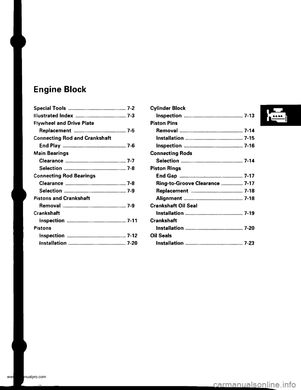
Engine Block
Speciaf Tools .............7-2
lllustrated lndex ................................... 7-3
Flywheel and Drive Plate
Replacement ..,.,....7-5
Connecting Rod and Grankshaft
End Play .................7-6
Main Bearings
Cfearance ...............7 -7
Selection ................7-8
Connecting Rod Bearings
Clearance ...............7-8
Selection ................7-9
Pistons and Crankshaft
Removal .................7-9
Crankshaft
Inspection .............. 7-11
Pistons
fnspection ..............7-12
fnstaflation .............7-20
Cylinder Block
Inspection ..............7-13
Piston Pins
Removal ..,.......,,..... 7-14
Installation ............. 7-15
Inspection .............. 7-16
Connecting Rods
Selection ................7 -14
Piston Rings
End Gap .................7 -17
Ring-to-Groove Clearance ............... 7 -17
Replacement .........7-18
Alignment .............. 7-18
Crankshaft Oil Seal
lnstallation ............. 7-19
Crankshaft
lnstalfation .............7-20
Oil Seals
fnstalfation ....,..,.....7-23
www.emanualpro.com
Page 149 of 1395

lllustrated lndex
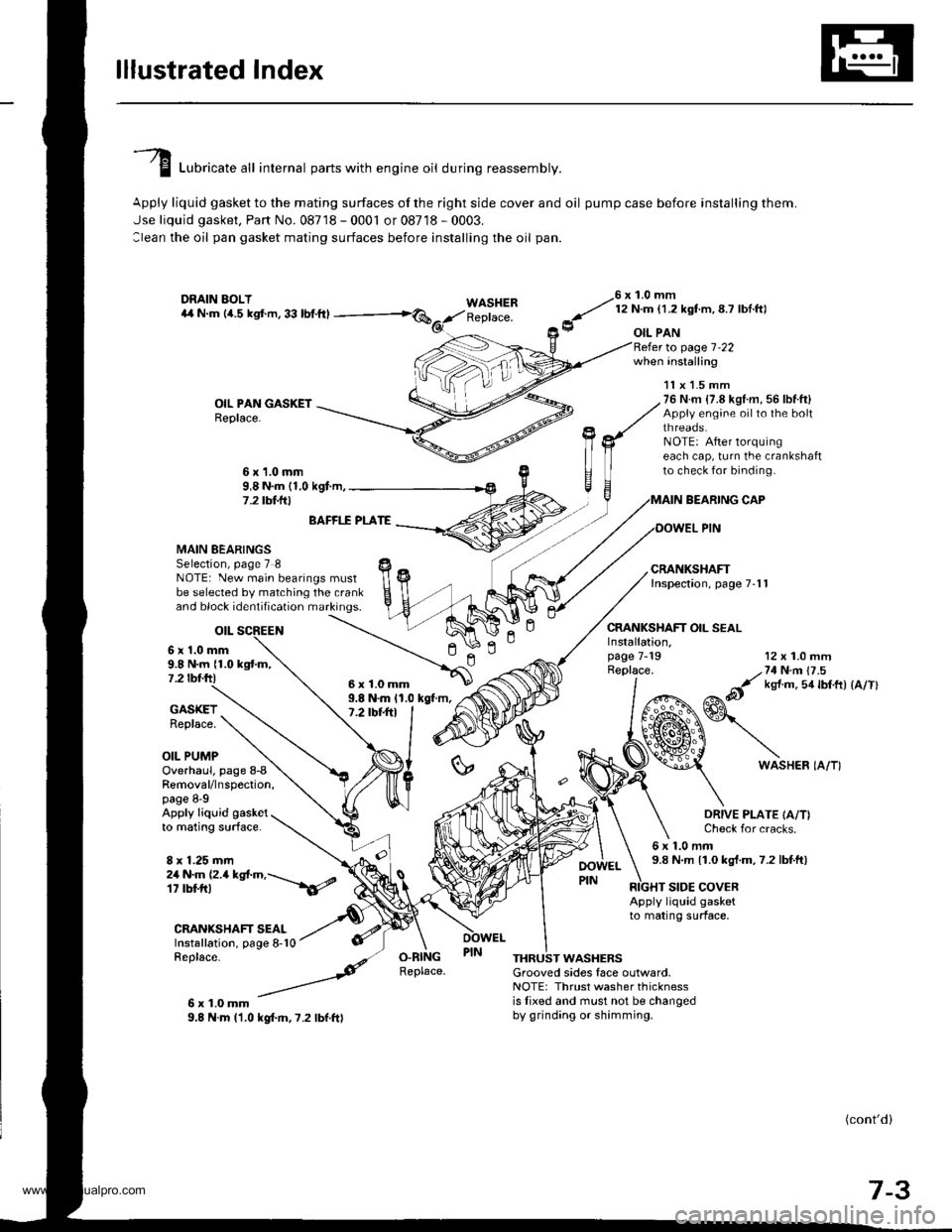
I Luori""t" "tl internal parts with engine oil during reassembly.
Apply liquid gasket to the mating surfaces of the right side cover and oil pump case before installing them.
Jse liquid gasket, Part No. 08718 - 0001 or 08718 - 0003.
:lean the oil pan gasket mating surfaces before installing the oil pan.
WASHERReplace.
76 x 1.0 mm
y' t:n- l.zxstm, 8.7 lbl ftl
9 oIL PAN
OIL PAN GASKETReplace.
to page 1-22when installing
BEARING CAP
OOWEL PIN
CRANKSHAFT OIL SEAL
11x 1.5 mm76 N.m {7.8 kgl.m, 56 lbf.ft}Appiy engine oilto the boltthreaos.NOTE: After lorquingeach cap, turn the crankshaftto check for binding.6x1.0mm9,8 N.m (1,0 kgf.m,7 .2 tbt.lrl
n
MAIN BEARINGSSelection, page 7 8NOTE: New main bearings mustbe selected by matching the crankand block identification markings.
otL
6 x'1.0 mm9.8 N.m {1.0 kgtm,7.2 tbf.ftl
BAFFI.f PLATE
9.8 N.m 11.0 kgt m,7.2 tbt+tl
12 x 1.0 mm
/,71N n 17 .5
&it ks{ m 5a lbtft) {a/Tl
GASKETReplace.
OIL PUMP
Installation,page 7-19Replace.
ln
6WASHER IA/T}Overhaul, page 8-8Removal/lnspection,page 8-9Apply liquid gasketto mating surface.
8 x 1.25 mm
ORIVE PLATE IA/T)Check for cracks.
6x1.0mm9.8 N.m 11.0 kgt.m,7.2 lbtft)2a N.m (2.a kgt.m,---\6/
CRANIGHAFT SEALInstallation, page 8-10Replace-
6x1.0mm9.8 N.m l'1.0 kgf.m,7.2 lbf.ft)
RIGHT SIDE COVERApply liquid gasketto mating surface,
O.RINGReplace.THRUST WASHERSGrooved sides face outlvard,NOTE: Thrust washer thicknessis lixed and must not be changedby grinding or shimming.
(cont'd)
7-3
6x1.0mm
www.emanualpro.com
Page 165 of 1395
Crankshaft Oil Seal
Rotate the rings in their grooves to make sure they
do not bind.
Position the ring end gaps as shownl
SECOND RING GAP
Appror.90"
DO NOT position any ring gap
at piston thrust surfaces,
OIL RINGGAPAppror.90'TOP RI.IIG GAPSPACER GAP
DO NOT position any ring gap
in line with the piston pin hole.OIL RING GAP
1.
lnstallation
The seal mating surface on the block should be dry
Apply a light coat of oil to the crankshaft and to the
lip of the seal.
Drive the crankshaft oil seal squarely into the right
sroe cover.
DRIVER
lnstall seal with thepart number sidefacing out.
Confirm that the clearance is equal all the way around
with a feeler gauge.
Clearance:0.5 - 0.8 mm {0.02 - 0.03 inl
NOTE| Refer to pages 7 23 and 8-10 for installation
of the oil oumD side crankshait oil seal.
0.5-0.8 mm{O.02 0.03 in)
7-19
www.emanualpro.com
Page 168 of 1395
Crankshaft
12.
Installation (cont'd)
14.
13.
Apply liquid gasket to the oil pump mating surfaceof the block.
Apply a light coat of oil to the crankshaft, the lip ofthe seal, and the O-rings.
Apply grease to the lips of the oil seals.
Align the inner rotor with the crankshaft, then installthe oil pump. When the pump is in place, clean anyexcess grease off the crankshaft, then check that theoil seal lips are not distoned.
6x1,0mm9.8 N.m {1.0 kg{.m,,.2 tbf.ftl
I
{/^ I GASKET(..6 Replace."[z
O-RINGReplace.
OIL PUMP
6x1.0mm9,8 N.m 11.0 kg{.m,7.2lbt.trl
8 x 1.25 mm24 N.m {2.4 kgf.m,17 tbt.ftl
7 -22
,'t ./o,DowEL PtN
// |
16.Apply liquid gasket on
cover matrng areas.
CYLINDERBLOCK
the oil pump and right side
Apply liquid g€sketto these pornts.
17. Install the oil pan gasket and oil pan. Wait no
than five minutes after applying liquid gasket.
OIL PAN
OIL PANGASKETReplace.
Apply liquid gasketto these pornts,
www.emanualpro.com
Page 169 of 1395
Oil Seals
18. Tighten the bolts and nuts finger tight at six points.
Tighten all bolts and nuts, starting from nut O. clock-
wise in three steps. Excessive tightening can cause
distortion ot the oil pan gasket and oil leakage.
Torque: 12 N.m (1.2 kgt.m,8.7 lbtft)
19.
1.
lnstallation
Dry the crankshaft oil seal housing.
Apply a light coat of grease to the crankshsft and to
the lips of the seals.
Using the special tool, drive in the timing pulley-end
seal until the driver bottoms against the oil pump.
When the seal is in place, clean any excess grease
off the crankshaft and check that the oil seal lip is
not distorted,
SEAL DRIVEROTLAD - PT3O1OAlnstall sealwith theparts number sidefacing out.
(cont'd)
7-23
www.emanualpro.com
Page 170 of 1395
Oil Seals
Installation (cont'dl
4. l/easure the flywheel-end seal thickness and the oil
seal housing depth. Using the special tool, drive theflywheel end seal into the rear cover to the point
where the clearance between the bottom of the oil
seal and the right side cover is 0.5 - 0.8 mm (0.02 -
0.03 in) (see page 7-19). Align the hole in the driverattachment with the pin on the crankshaft.
DRIVERATTACHMENT76x80mm07948 - 5800101Install sealwith thenumber side facingout,
<:
7 -24
www.emanualpro.com
Page 172 of 1395
Special Tools
Ret. No. I Tool NumberIDescriptionOty i Pagc Roforance
oOTLAD _ PT3O1OA
079'12 - 6110001
Seal Driver
Oil Filter Wrench
1
1
8-10
8-6
8-2
www.emanualpro.com
Page 173 of 1395
lllustrated Index
OIL CONTROLORIFICE
OIL PUMPOverhaul, page 8-8Removal/lnspection, page 8 IApply liquid gasket tomating surface of engine block.
'99 - 00 models:KNOCK SENSOR31 N.m {3.2 kgf.m.23 lbl.ft)
ENGINE OIL PRESSURE SWITCH18 N.m {1.8 kgtm, 13lbl.ft)1/8 in. BSPT (British StandardPipe Taper) 28 Threads/inch.Use proper liquid sealant.
O-RING
DOWEL PIN
6x1.0mm9.8 N.m (1.0 kgf.m,7.2 tbl.ft)
8 x 1.25 mm24 N.m 12.4 kgf.m,17 tbf.ft)
BAFFLE PLATE
kgtm,7.2 lbtftl
Replace.
6x1.0mm9.8 N.m 11.0 kgf m,7.2 tbf.ftl
OIL PANGASKETReplace.
OIL PANBeferto page 7 22when installing.
6x1.0mm12 N.m 11.2 kglm,8.7 lblftl
WASHEBReplace.
DRAIN BOLT4,1N.m {,1.5 kgf'm,33 lbf ft)Do not overtighten.
'-- /o-RrNG ,/ Reptace.
\^ ./
v,/
U
6x1.0mm9.8 N.rn {1.0
SCREEN
8-3
www.emanualpro.com