1998 HONDA CR-V 700
[x] Cancel search: 700Page 579 of 1395
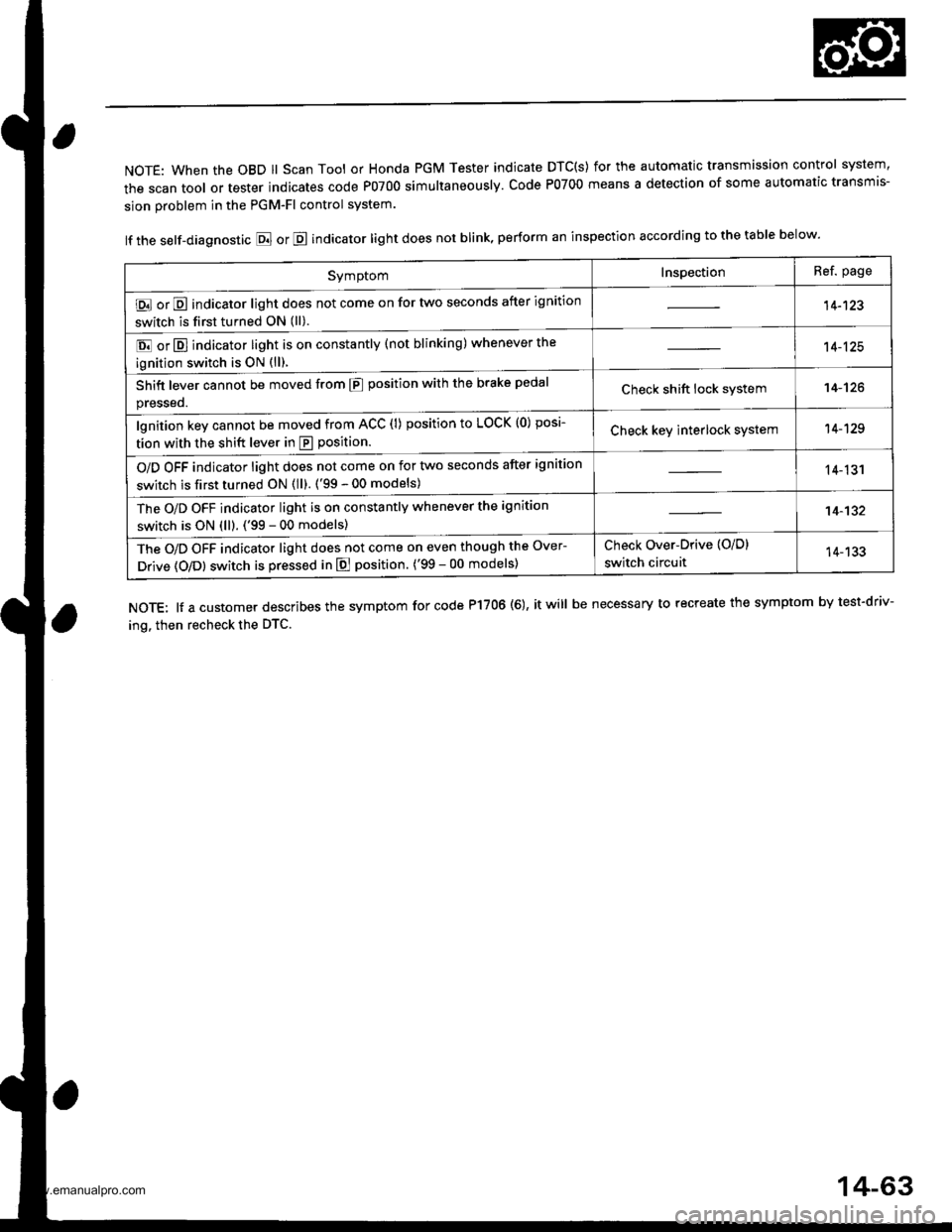
NOTE: When the OBD ll Scan Tool or Honda PGM Tester indicate DTC(S) for the automatic transmission control system,
the scan tool or tester indicates code P0700 simultaneously. Code P0700 means a detection of some automatic transmis-
sion problem in the PGM-Fl control system.
lf the self-diagnostic E or E indicator light does not blink, perform an inspection according to the table below.
NOTE: lf a customer describes the symptom for code P17OO (6), it will be necessary to recreate the symptom by test-driv-
ing. then recheck the DTC.
SymptomInspectionRef. page
E or E indicator light does not come on for two seconds after ignition
switch is first turned ON (ll).14-123
E or E] indicator light is on constantly (not blinking) whenever the
ignition switch is oN {ll).
14-125
Shift lever cannot be moved from E position with the brake pedal
presseo.Check shift lock system14-'t26
lgnition key cannot be moved from ACC (l) position to LOCK (0) posi-
tion with the shift lever in E position.Check key interlock system14-129
O/D OFF indicator light does not come on for two seconds after ignition
switch is first turned ON (ll). ('99 - 00 models)14-131
The O/D OFF indicator light is on constantly whenever the ignition
switch is ON (ll). ('99 - 00 models)14-132
The O/D OFF indicator light does not come on even though the Over-
Drive (O/Dl switch is pressed in E position. ('99 - 00 models)
Check Over-Drive {O/D}
switch circuit14-133
14-63
www.emanualpro.com
Page 675 of 1395
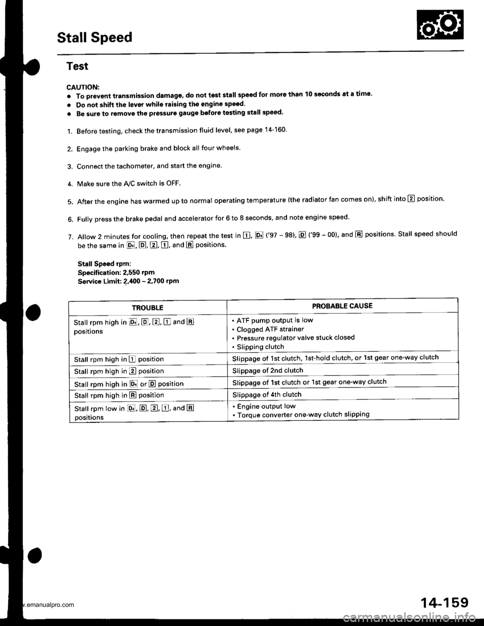
Stall Speed
Test
CAUTION:
. To prevent transmission damage, do not te3t stall speed for mors than 10 s€€onds at a time'
. Do not shift the lever while raising th€ engine spsed.
. Be sure to remove tho pressuro gauge bofore testing stall speed,
1. Before testing, check the transmission fluid level, s€e page 14-160.
2. Engage the parking brake and block all four wheels
3. Connect the tachometer, and start the engane.
4. Make sure the Ay'C switch is OFF
5. After the engine haswarmed upto normal operating temperature (the radiator fan comes on),shiftinto@ position.
6. Fully press the brake pedal and accelerator for 6 to 8 seconds, and note engine speed '
j. A|ow 2 minutes for cooling, then repeat the test in E, E ('97 - 98). E {'99 - 00}, and E positions. Stall speed should
be the same in E, E, E, tr. and E positions
Stall Speed rpm:
Specitication: 2,550 rpm
S€rvice Limit: ?,400 - 2.700 rpm
TROUBLEPROBAELE CAUSE
Stall rpm high in El, E, E, E and E
positions
ATF pump output is low
Clogged ATF strainer
Pressure regulator valve stuck closed
Slipping clutch
Stall rpm high in E positionSlippage of 1st clutch, 1st-hold clutch, or 1st gear one-way clutch
Stall rpm high in E positionSlippage of 2nd clutch
stall rpm high in E! or E positionSlippage of 1st clutch or 1st gear one-way clutch
Stall rpm high in E positionSlippage of 4th clutch
Stall rpm low in [dd, E. E, E, ana E
positions
. Engine output low
. Torque converter one-way clutch slipping
14-159
www.emanualpro.com
Page 900 of 1395
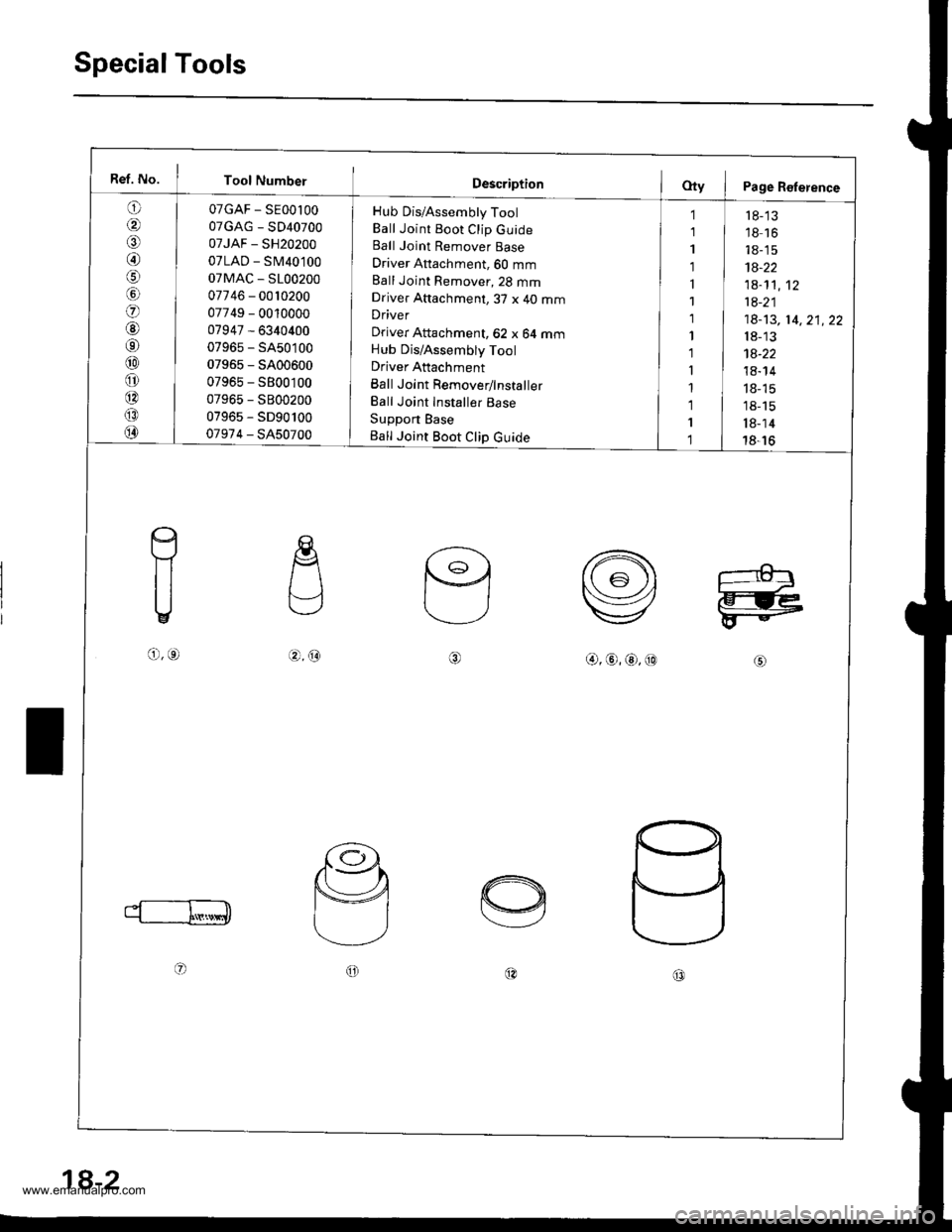
SpecialTools
Ref. No. I Tool Number
o
/a
@/6
lol
o
@6r
@
o
@
@
@
07GAF - SE00l00
07GAG - SD40700
07JAF - SH20200
07LAD - SM40100
07MAC - S100200
07746 - 0010200
07749 - 0010000
07947 - 6340400
07965 - SA50100
07965 - 5400600
07965 - S800100
07965 - S800200
07965 - SD90100
07974 - SA50700
Hub Dis/Assembly Tool
Ball Joint Boot Clip GuideBall Joint Remover Base
Driver Attachment, 60 mm
Ball Joint Remover,23 mmDriver Attachment,3T x 40 mmDriver
Driver Attachment, 62 x 64 mmHub Dis/Assembly Tool
Driver Attachment
Ball Joint Remover/lnstaller
Ball Joint Installer Base
Support Base
Ball Joint Boot Clip Guide
1
1
1
1
1
1
1
1'l
I
1
1
I
1
r 8-'13'18 16
18-15
1A-22
1a-1't,12
1a-21
18-13, 14,21,22
18-13
1a-22
18- 14
18- 15
18-15
l8-14
18-16
c
f1
U
o,o.4.@@,@,@,@
oo@c0
18-2
www.emanualpro.com
Page 941 of 1395
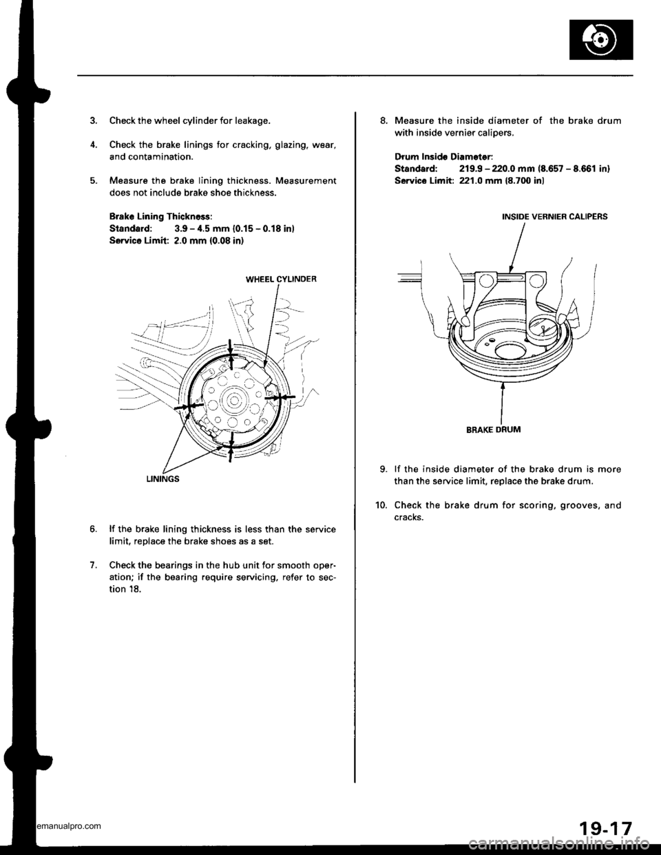
Check the wheel cylinder for leakage.
Check the brake linings for cracking, glazing, wear,
and contamination.
Measure the brake lining thickness. Measurement
does not include brako shoe thickness.
Brake Lining Thicknoss:
Standard: 3.9 -,1.5 mm {0.15 - 0.18 inl
Sorvice Limil: 2.0 mm {0.08 in}
lf the brake lining thickness is less than the service
limit, replace the brake shoes as a set.
Check the bearings in the hub unit for smooth oper-
ation; if the bearing require servicing. refer to sec-
tion 18.
7.
WHEEL CYLINOER
LININGS
8. Measure the inside diameter of the brake drum
with inside vernier calioers,
Drum Insido Diamoter:
Standard: 219.9 - 220.0 mm (8.657 - 8.661 in)
Service Limit: 221.0 mm {8.700 inl
lf the inside diameter of the brake drum is more
than the service limit, replaca the brake drum.
Check the brake drum for scoring, grooves, and
cracKs.
10.
BRAKE DRUM
19-17
www.emanualpro.com
Page 1089 of 1395
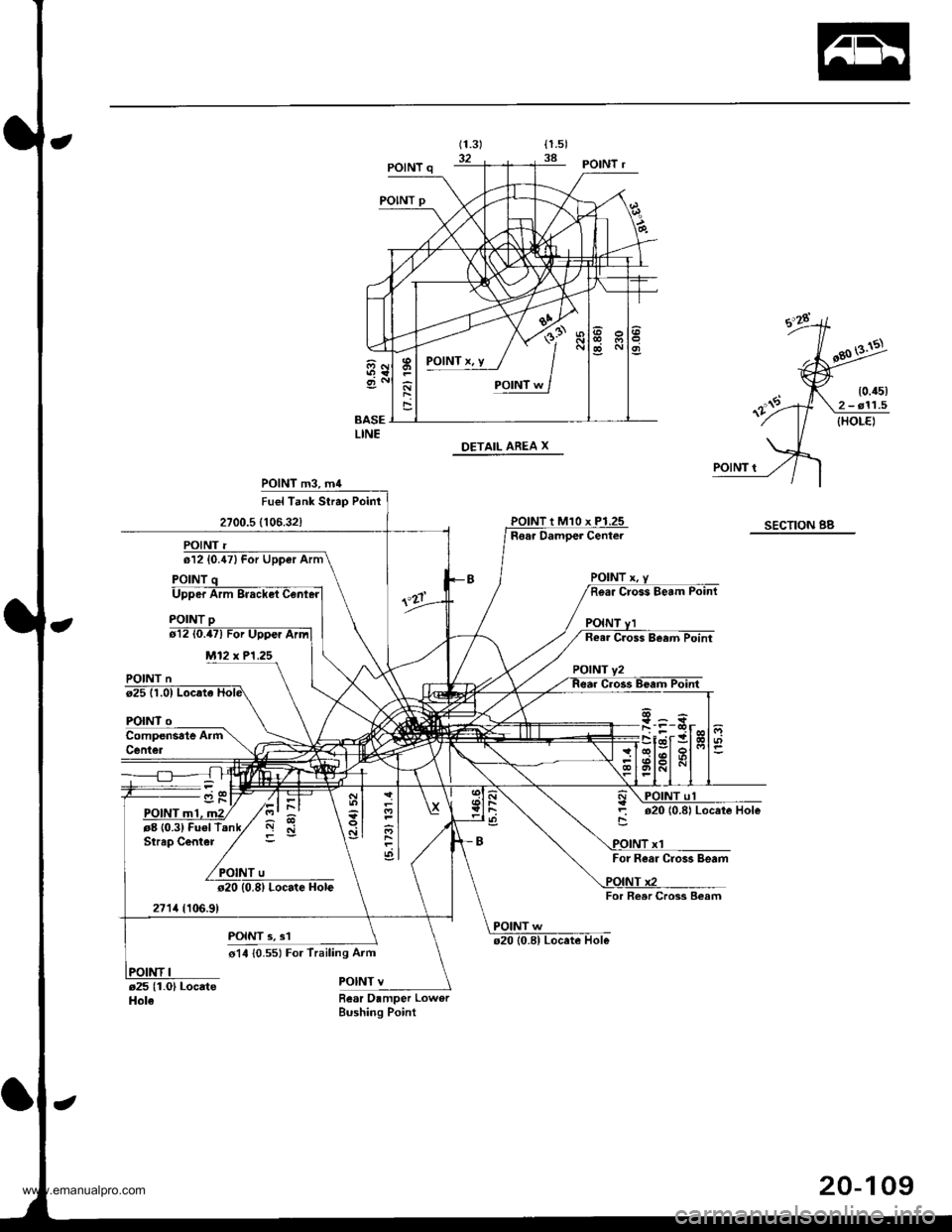
POlNTx.y / I
'sad
POINT m3, m4
Upper Arm
M12 x P1.25
Locate Hole
POINT 3, s1
o14 {0.551 For Trailing Aim
POINT v
Fuel Tank Strap Poinr
2700.5 (106.32)SECTION BBRear Damoer Center
POINT n
FOINT
rg (0.3) Fuel TStrap Center
271,1(10,6.9)
o2010.8| Locate Hole
For Rear Cros3 Beam
For Reer Cross Beam
POINT w
Bear Damper LowerBushing Point
I
\-
ql
ol
.df
20-109
www.emanualpro.com
Page 1150 of 1395
A/C System Service
Evacuation
Use only service equipment that is U.L.-listed and is cer-tified to meet the requirements of SAE J2210 to removeHFC-134a {R-134a)from the air conditioner system.
CAUTION: Exposure to air conditioner refrigerant andlubricant vapor or mist can irrhate eyes, noso and throat.Avoid breathing the air condhioner retrigerant and lubri-cant vapor or mist.
lf accidental system discharge occu.s. ventilate workarea before resuming service.
R 134a service equipment or vehicle air conditioner sys-tems should not be pressure tested or leak tested withcompressed arr.
!@ some mixtures of air and R-134a hsvo beenshown to be combustible at elevated pressures and canresult in tire or explosion causing iniury ot property
damage. Never use compressed air to pressure test R-134a service equipment or vehicle air conditioner svs-tems.
Additional health and safety information may be obtainedfrom the refrigerant and lubricant manufacturers.
1, When an A,/C System has been opened to the atmo-
sphere, such as during installation or repair, it must
be evacuated using a R-l34a refrigerant recovery/
recycling/charging station. {lf the system has beenopen for several days, the receiver/dryer should bereplaced, and the system should be evacuated forseveral hours.)
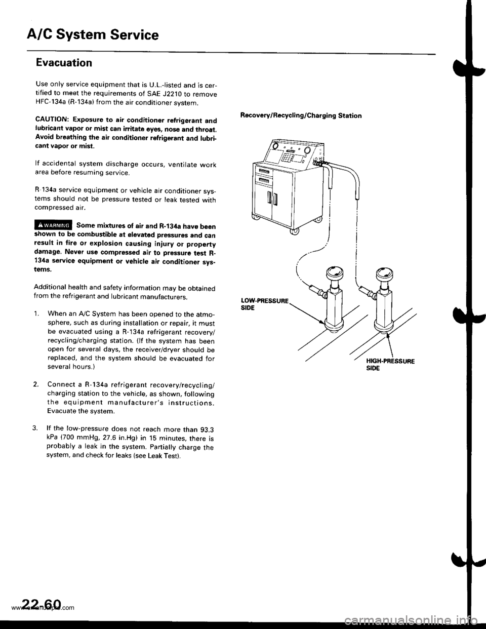
Connect a R-134a refrigerant recovery/recyclin g/
charging station to the vehicle, as shown, following
the equipment manufacturer's instructions.
Evacuate the system,
lf the low-pressure does not reach more than 93.3kPa (700 mmHg,27.6 in.Hg) in 15 minutes, there isprobably a leak in the system. partially charge thesystem, and check for leaks (see Leak Test).
Recovery/Recycling/Charging Station
22-60
www.emanualpro.com
Page 1151 of 1395
Charging
Use only service equipment that is U.L.-listed and is cer-
tified to meet the requirements of SAE J2210 to remove
HFC-134a (R-134a) from the air conditioner system.
CAUTION: Exposure to air conditioner refrigerant and
lubricant vapor or mist can irritate eyes, nose and
throat. Avoid breathing th€ air conditioner refrigerant
and lubricant vapor or mist.
lf accidental system discharge occurs, ventilate work
area before resuming service. Additional health and
safety information may be obtained from the relrigerant
and lubricant manufacturers.
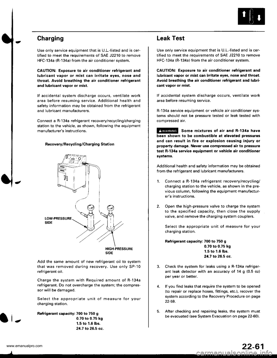
Connect a R-'134a refrigerant recovery/recycling/charging
station to the vehicle, as shown. following the equipment
manufacturer's instructions.
R€covery/Recycling/Charging Station
HIGH-PRESSURESIDE
Add the same amount of new refrigerant oil to system
that was removed during recovery. Use only SP-'10
refrigerant oil.
Charge the system with Required amount of R-134a
refrigerant. Do not overcharge the system; the compres-
sor will be damaged.
Select the appropriate unit of measure for your
charging station.
Refrigerant capacity: 700 to 750 g
0.70 to 0.?5 k9
1.5 to 1.6 lbs.
21.7 to 26.5 oz.
ll-
22-61
Leak Test
Use only service equipment that is U.L.-listed and is cer-
tified to meet the requirements of SAE J2210 to remove
HFC-134a (R-134a) from the air conditioner system.
CAUTION: Exposure to air conditionor refrigerant and
lubricant vapor or mist can irritate eyes, nose and throat.
Avoid breathing the air conditioner retrigerant and lubri-
cant vapor or mist.
lf accidental system discharge occurs, ventilate work
area before resuming service.
R-134a service equipment or vehicle ajr conditioner sys-
tems should not be pressure tested or leak tested with
compressed arr.
!@ some mixturos of air and R-1348 have
been shown to be combustible at olovatod pres3uras
and can result in fire or explosion causing iniury or
property damage. Never use comprelised air to pressure
test R-13ila service equipment or vehicle air conditioner
systems.
Additional health and safety information may be obtained
from the refrigerant and lubricant manufacturers.
2.
1.Connect a R-134a refrigerant recove rylrecycling/
charging station to the vehicle, as shown in the pre-
vious column, following the equipment manufactur-
er's instructions.
Open the high-pressure valve to charge the system
to the specified capacity, then close the supply
valve, and remove the charging system couplers.
Select the appropriate unit of measure for your
charging station.
Refrigerant capacity: 700 to 750 g
0.70 to 0.75 kg
1.5 to 1.6 lbs.
21.7 to 26.5 oz.
Check the system for leaks using a R-134a refriger-
ant leak detector with an accuracy of 14 g (0.5 ozl
per year or better.
lf you find leaks that require the system to be opened
(to repair or replace hoses, fittings, etc.), recover the
system according to the Recovery Procedure on page
22-59.
After checking and repairing leaks, the system must
be evacuated (see System Evacuation on page 22-601.
5.
www.emanualpro.com