1998 HONDA CR-V 700
[x] Cancel search: 700Page 32 of 1395
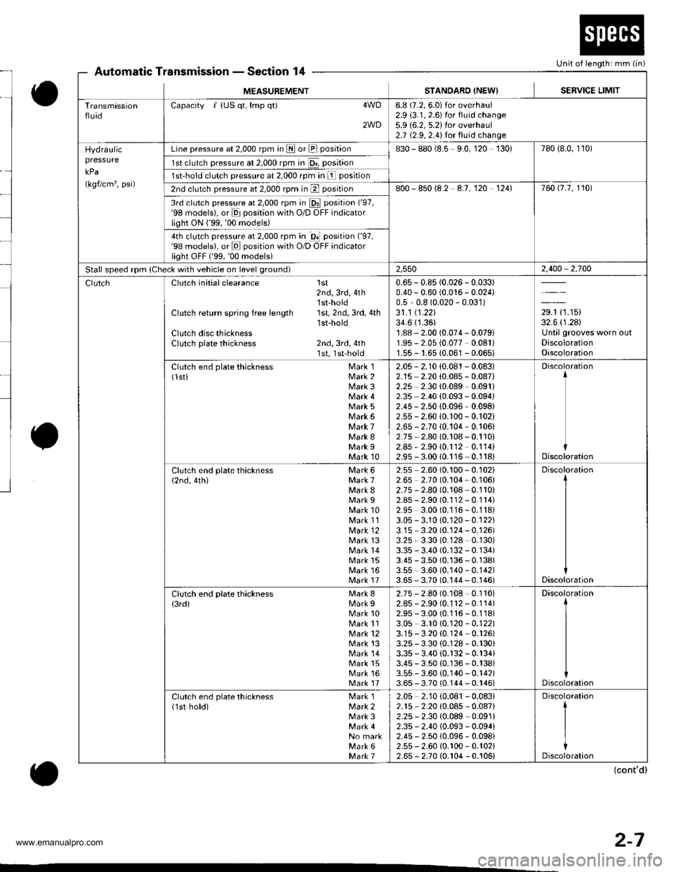
Unit of length: mm (in)Automatic TransmissionSection 14
MEASUREMENTSTANDARO INEW}SERVICE LIMIT
TransmissionfluidCapacity I {US qt, lmp q0 4WD
2WD
6.8 (7.2, 6.0) for overhaul2.9 (3.1, 2.6) for fluid change5.9 {6.2, 5.2)for overhaul2.7 {2.9, 2.4}for fluid change
Hydraulicpressure
kPa
(kgflcm'�, psi)
Line pressure at 2,000 rpm in LII or El position830 - 880 (8.5 - 9.0, 120 130)780 (8.0, 1'�t0)
1sl clutch pressure at 2,000 rpm in Da position
1st-hold clutch pressure at 2,000 rpm In l position
2nd clutch pressure at 2,000 rpm in El position800 - 850 (8.2 4.7,120 1241760 t7.7, 1101
3rd clutch pressure at 2,000 rpm in E position ('97,'98 models), or E position with O/D OFF indicatorlight ON ('99,'00 models)
4th clutch pressure at 2,000 rpm in gl position ('97,'98 models), or E position with O/D OFF indicatorlight oFF ('99,'00 models)
Stall speed rpm (Check with vehicle on level ground)2,5502,400,2,700
Clutch initial clearance 1st2nd,3rd,4th'lst-hold
Clutch return spring free length 1st, 2nd, 3rd, 4th'1st-hold
Clutch disc thicknessClutch plate thickness 2nd, 3rd, 4th1st, 1st-hold
0.65 - 0.85 (0.026 -0.033)
0.40 - 0.60 (0.016 - 0.024)0.5 - 0.8 (0.020 - 0.031)31 .1 11 .22)34.6 (1.36)
1.88 - 2.00 (0.074 - 0.079)'r.95 - 2.05 {0.077 0.081)'1.55- 1.65 (0.061 - 0.065)
29.1 (1.15)
32.6 (r.28)
Until grooves worn outDiscolorationDiscoloration
Clutch end plate thickness Mark 1(lsti Mark 2Mark 3Mark 4Mark 5Mark 6Mark 7Mark 8Mark IMark 10
2.05 - 2.r0 (0.081 - 0.083)2.15 2.20 (0.085 - 0.08712.25 2.30 (0.089,0.091)
2.35 2.40 {0.093 - 0.094}2.45 - 2.50 {0.096- 0.098}2.55 - 2.60 (0.100 - 0.102)2.65 - 2.70 (0.104 - 0.106)2.75 2.80 i0.108 - 0.110)2.85 - 2.9010.r 12 0.114)2.95 - 3.0010.116 0.118)
Discoloration
Discoloration
Clutch end plate thickness Mark 6{2nd, 4th) Mark 7Mark 8Mark 9Mark 10Mark 11lvlark 12Mark 13Mark 14Mark 15Mark 16Mark 17
2.55 2.60 10.100 - 0.102)2.65 2.70(0.104,0.106)2.75 - 2.80 (0.108 0.110)2.85 - 2.90 (0.112 -0.rr4)
2.95 3.00 (0.116-0.118)
3.05 - 3.10 (0.120 - 0.122)3.15 3.20 (0.124-0.126)
3.25 - 3.30 (0.128 0.130)3.35 - 3.40 (0. r32 - 0.134)3.45 - 3.50 (0.136 - 0.138)3.55 3.60 (0.140 - 0.142)3.65 - 3.70 (0.144 - 0.146)
Discoloration
Discoloration
Clutch end plate thickness Mark 8
{3rdi Mark IMark 10Mark 11Mark 12Mark 13Mark 14Mark 15Mark 16Mark 17
2.75 - 2.80 (0.108 0.110)2.85- 2.90 (0.112 - 0.114)2.95 - 3.00 (0.116 - 0.1'�j8)3.05 3.10 (0.120 - 0.122)3.15-3.20 {0.124 0.126)3.25 - 3.30 (0.128 - 0.r30)3.35 - 3.40 (0.132 - 0.r34i3.45 - 3.50 (0.136 - 0.138)3.55 - 3.60 {0.140 - 0.142)3.65 - 3.70 {0.144 - 0.r46)
Discoloration
Discoloration
Clutch end plate thickness Mark 1(1st hold) Mark 2Mark 3
No markMark 6Mark 7
2.05 2.10 (0.081 - 0.08312.r5 2.20 (0.085 - 0.087)2.25 - 2.30 {0.089 - 0.091}2.35 - 2.40 10.093 - 0.094i2.45 - 2.50 (0.096- 0.098i2.55 - 2.60 (0.r00 - 0.102)2.65 - 2.70 (0.r04 - 0.106)
(cont'd)
2-7
www.emanualpro.com
Page 279 of 1395
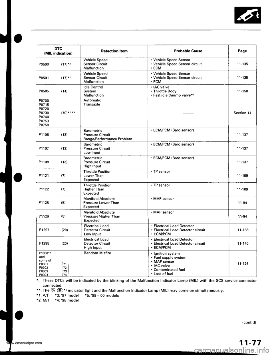
DTC(MlL indicationlDotection ltomProbable CausePage
P0500 t17)*,
Vehicle SpeedSensor CircuitMalfunction
Vehicle Speed SensorVehicle Speed Sensor circu itECtVI1 1-135
P0501 l17J*1
Vehicle SpeedSensor CircuitMalfunction
Vehicle Speed SensorVehicle Speed Sensor circuitPCM11-135
P0505 (14)ldle ControlSystemMalfunction
IAC valveThrottle BodyFast idle thermo valve*11 '�]- 150
P0700P0715PO720P0730P0740P0753P0758
AutomaticTransaxle
Section l4
P1106 (13)BarometricPressure CircuitRange/Performance Problem
ECM/PCM (Baro sensor)
11-137
P1107 (13)BarometricPressure CircuitLow InPut
. ECM/PCM {Baro sensor)11-137
P1108 (13)BarometricPressure CircuitHigh Inpur
ECM/PCM {Baro sensor)11,137
P1121 (7)Throttle PositionLower ThanExpected
. TP sensor11-109
P1122 (7)Throttle PositionHigher ThanExpected
' TP sensor1 1-'109
P112a (5)Manifold AbsolutePressure Lower ThanExpected
. MAP sensor11-94
P1129 (5)Manifold AbsolutePressure HiqherThanExpected
' MAP sensor1l-94
P1297 (20)Electrical LoadDetector CircuitLow Input
Electrical Load DetectorElectrical Load Detector circuitECM/PCM1 1- 138
P1298 (20)Electrical LoadDetector CircuitHigh Input
Electrical Load DetectorElectrical Load Detector circuitECM/PCM11-140
P1300'3
P0301P0302P0303P0304
7l721314
Random lvlisfirelgnition systemFuel supply systemMAP sensorIAC valveContaminated fuelLack offuel
11-126
*: These DTCS will be indicated by the blinking of the Malfunction Indicator Lamp {MlL} with the SCS service connector
connected.**:The E (E])+s indicator light and the Malfunction Indicator Lamp (MlL) may come on simultaneously.*1:A,./T "3: '97 model +5: '99 - 00 models*2: M/T *4:'98 model
{cont'd)
11-77
www.emanualpro.com
Page 333 of 1395
tro-rsl
1Tffi61
tF136t
fPfa6r-1
tF138tl
I-Pi382l
Crankshaft Position/Top Dead Genter/Gylinder Position (CKP/TDC/CYPI Sensor
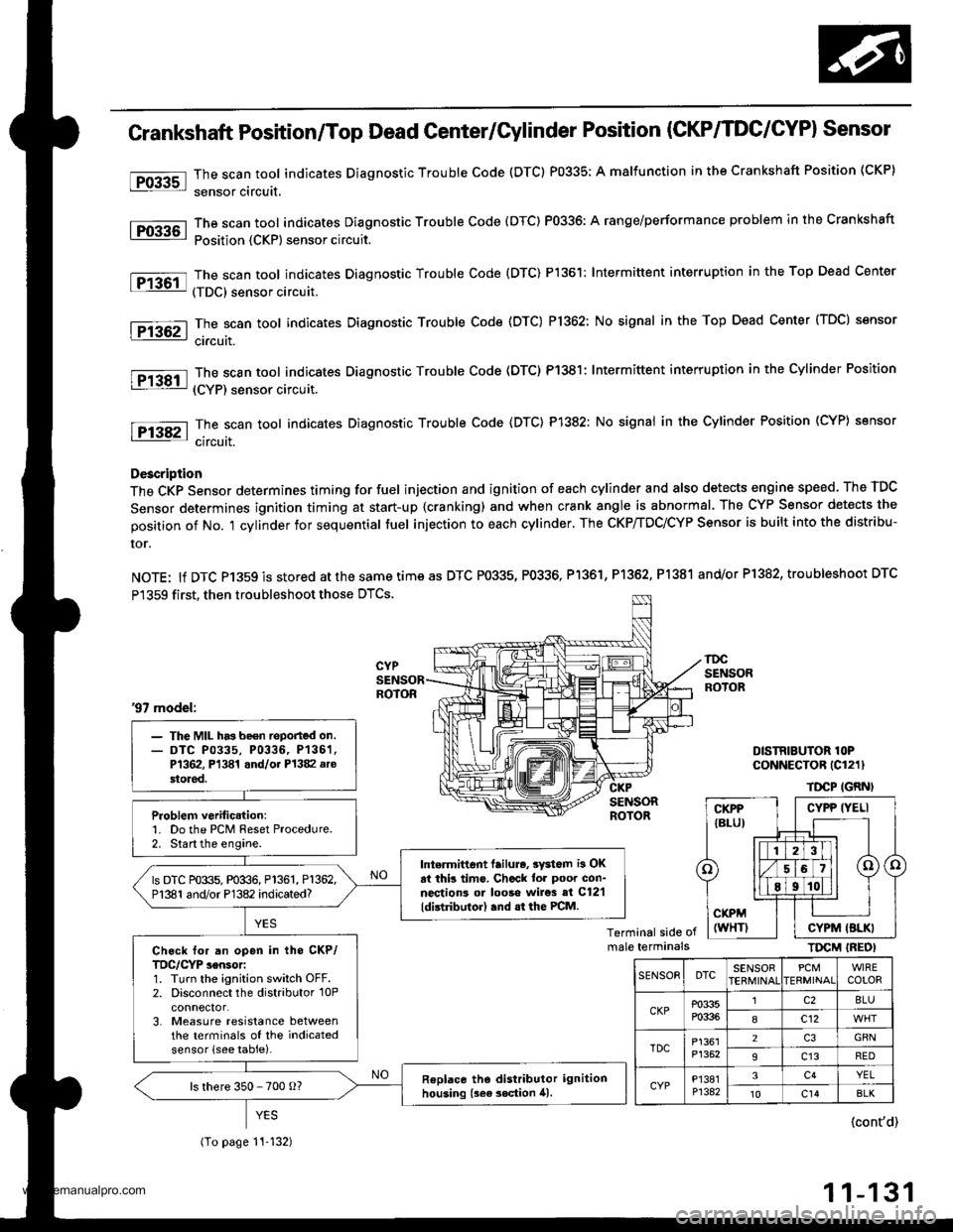
The scan tool indicates Diagnostic Trouble Code (DTC) P0335; A malfunction in the Crankshaft Position (CKP)
sensor circuit,
The scan tool indicates Diagnostic Trouble Code (DTC) P0336: A range/performance problem in the Crankshaft
Position {CKP) sensor circuit.
The scan tool indicates Diagnostic Trouble Code {DTC) P1361: Intermittent interruption in the Top Dead Center
(TDC) sensor circuit.
The scan tool indicates Diagnostic Trouble Code (DTC) P1362: No signal in the Top Dead Center (TDC) sensor
ci.cuit.
The scan tool indicates Diagnostic Trouble Code (DTC) P1381: Intermittent interruption in the Cylinder Position
(CYP) sensor circuit.
The scan toot indicates Diagnostic Trouble Code {DTC) P1382: No signal in the Cylinder Position (CYP} sensor
circuit.
Description
The CKP Sensor determines timing for fuel injection and ignition of each cylinder and also detects engine speed. The TDC
Sensor determines ignition timing at start-up {cranking) and when crank angle is abnormal. The CYP Sensor detects the
position of No. 't cylinder for sequential fuel injection to each cylinder. The CKP/TDC/CYP Sensor is built into the distribu-
ror.
NOTE: lf DTC P1359 is stored atthesametimeas DTC P0335, P0336, Pl361, P1362, P1381 and/or P1382, troubleshoot DTC
P1359 first, then troubleshoot those DTCS.
DISTRIBUTOR lOPCoNNECTOR (Cl211
TDCP IGRNI
Terminal side ofmale terminalsTIrcM IREOI
'97 model:
- The MIL has be€n reported on.- DTC P0335, P0336, P136'�1,P1362, Pl341 and/oi P1382 arestored.
Problem verific.tion:1. Do the PCM Reset Procedure.2. Start the engine.
Intermittent lailure, 3yd6m i3 OKat thb tims. Chcck tor poor con-nections ol looso wire3 si C12'l
ldistributor) .nd .t the PCM.
ls DTC P0335, P0336, P1361, P1362,P1381 and/or P1382 indicated?
Ch.ck for an open in tho CKP/TDC/CYP sensor:1. Turn the ignition switch OFF.2. Disconnect the distributor 10Pconnector.3. Measure resistance betweenthe terminals of the indicatedsensor (see table).
Replace tho distributor ignitionhousing {sea 3ection 41.ls there 350 - 700 o?
(To page 11-132)
CYPP IYELI
CYPM (BLKI
SENSOEDTCSENSOBPCMERMINAIWIRECOLOR
CKPP0335P0336
lc28LU
8c12
TDCP1361P1352
2GRN
9c13RED
CYPP'�I381P1342
3c4YEL't0c14BLK
{cont'd)
11-131
www.emanualpro.com
Page 334 of 1395
PGM-FI System
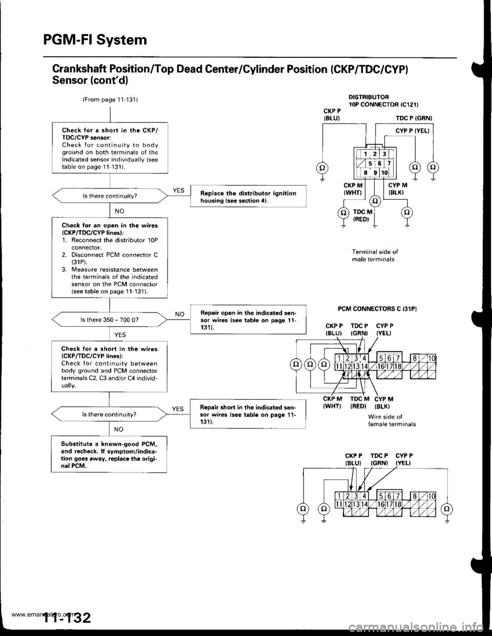
Grankshaft Position/Top Dead Center/Cylinder Position (CKP/TDC/CYPI
Sensor (cont'd)
DISTRIBUTOR10P CONNECTOR tCl2l)CKP P
IBLUITDC P {GRNI
PCM CONNECTORS C I31P)
CKP P TDC P CYP PIBLU) IGRNI IYEL}
Terminal side ofmale terminals
IREDI IBLK)
Wire side offemale terminals
{WHT)
{From page 1'1-131)
Check for a short in the CKP/TDC/CYP sensor:Check for continuity to bodyground on both terminals of theindicated sensor individually (see
table on page 1l 131).
R€plac€ the distributor ignitionhousing {see section 4}.ls there continuity?
Ch€ck fo. an open in the wires{CKP/TDC/CYP lines):'1. Reconnect the distributor 10Pconnector.2. Disconnect PCM connector C(31P).
3. Measure resistance betweenthe terminals of the indicatedsensor on the PCM connectorlseetable on page 1l 131).
Repair open in the indicated sen-sor wires {se6 table on page 11-131).ls there 350 - 700 0?
Check tor a short in the wires{CKP/TDC/CYP linesllCheck for continuity betweenbody ground and PCM connectorterminals C2, C3 and/or C4 individ-
R€Dair short in the indicatod sen-sor wires lsee table on page 11-13rI.ls there continuity?
Substitute a known-good PCM,and recheck. lf symptom/indica-tion goes away, r€place lhe origi-nal PCM.
CKP P TDC P CYP P
www.emanualpro.com
Page 335 of 1395
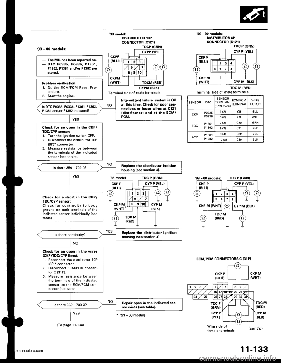
TDCP (GRN)
CYPP (YEL}
TDCM (REDI
'98 - 00 models:
'98 model:DISTRIBUTOR 1OPCoNNECTOR (C121)
CYPM IBLKI
Terminal side of male terminals
'99 - 00 modelr:DISTRIBUTOR 8PcoNNECTOR {C121)
TDC M (RED}
Terminal side of male terminals
CKP P
{BLU)
'98 modeliTDC P {GRNI
CKP MIWHT)
TOC P
IGRNI
CYP P(YEL)
(RED)
CYP M(BLKI
M
female terminals(cont'd)
1 1-133
TDC P (GNN}
CYP P IYEL}
CYP M IBLKI
SENSORDTCSENSORERMINAT):'99 mode
ECM/PCMIERMINAIWIRECOLOR
CKPP0335P0336
1 t2)c8BLU
8 (6)c9
TDCP1361Pl362
2 (3)c20GBN
9 (7)c21RED
CYPP]381P]382
3 (4)c29YEL
10 {8)c30BLK
ECM/PCM CONNECTOFS C {31P)
The MIL ha3 been reoorted on.DTC P0335. P0336, P1361,P1362. P1381 andlor P13V arestor€d,
Problem verification:1. Do the ECM/PCM Reset Procedure.2. Start the engine.Intermittant tailure, svstom is OKat this time. Check for poor con-nections or loose wirgs al C121{distributo.l .nd at the ECM/PCM.
ls DTC P0$5, m$6, Pl361, P1362,P1381 and/or Pl382 indicated?
Check for an open in th6 CKP/TDC/CYP sensor:1. Turn the ignition switch OFF.2. Disconnect the distributor 10P(8P)* connector.3, Measure resistance betweenthe terminals of the indicatedsensor {see table).
Rephce the distributor ignitionhouaing l3e9 3oction 4).ls there 350 700 0?
Check for a short in the CKP/TDC/CYP s€nsor:Check for continuity to bodyground on both terminals of theindicated sensor individually (see
table).
Replaco tho distributor ignitionhousing lsee soction tll.
Check for an op€n in th6 wiresICKP/TDC/CYP linesl:1. Reconnect the distributor 10P(8P)* connector.2. Disconnect ECM/PCM connec-tor C (31P).
3. Measure resistance betweenthe terminals of the indicatedsensor on the ECM/PCM connector (see table).
Repair open in the indicated sen-sor wires lsee t.ble).ls there 350 700 O?
(To page 11-134)
':'99 - 00 models
www.emanualpro.com
Page 352 of 1395

ldle Control System
ldle Control System
I P0505 | The scan tool indicates Diagnostic T.ouble Code (DTCI PO5O5: ldlecontrol svstem mattunction.
NOTE: lf DTC P1508 is stored at the same time as DTC P0505, troubleshoot DTC P1508 first. then troubleshoot DTC p0505.
Possibls Cause
. IAC valve mechanical malfunction. Throttle body clogged port, improper adlustment. Intake manifold gasket leakaging. Intake air hose loose leakaging. Vacuum hose leakaging
a ECT sensor incorrect output. Throttle Position sensor incorrect output
Troubleshooting Flowchart
The MIL has been reDorted on.DTC P0505 is sto.ed.
Problem verificationi1. Start the engine. Hold theengine at 3,000 rpm with noload (in Park or neutral) untilthe radiator Ian comes on, thenlet it idle.2. With the scan tool, check thelollowing items.- Throttle position should beapprox. 10% with the throt-tle {ully closed.- Engine coolant temperature shorJld be 194 - 205'F(90 - 96"C).lf they are not within thespec., repair the faulty sen-sor circuit.3 Check the engine speed atidle with no-load conditions:headlights, blower fan. reardefogger, radiator lan, and airconditioner are not operaling,
Inte.mittent failure. syltem is OKat this time.ls it 750 {730)* i 50 rpm?
ls il 700 (680)' rpm or less?
{To page 11-151)(To page 1'l-151)
l:'99 - 00 models
www.emanualpro.com
Page 572 of 1395
Troubleshooting Procedures
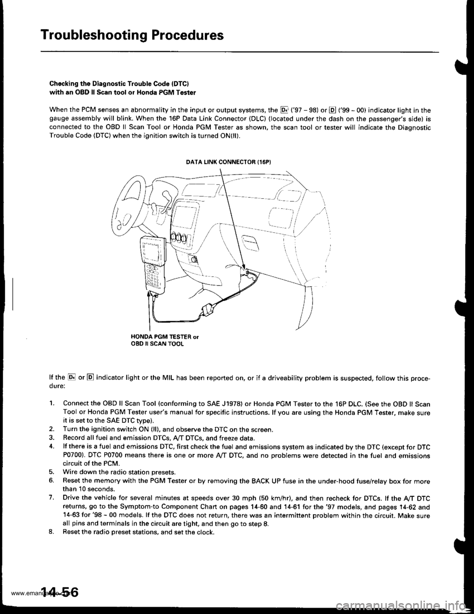
Checking ths Diagnostic Trouble Code (DTC)
with an O8D ll Scan tool or Honda PGM Tsster
When the PCM senses an abnormality in the input or output systems, the El ('97 - 98) or E ('99 - O0) indicator light in thegauge ass€mbly will blink. When the 16P Data Link Connector (DLC) {located under the dash on the passenger's side) is
connected to the OBD ll Scan Tool or Honda PGM Tester as shown, the scan tool or tester will indicate the Diagnostic
Trouble Code (DTC) when the ignition switch is turned ON(ll).
HONDA PGM TESTER olOBD II SCAN TOOL
lf the E or E indicator light or the MIL has been reported on, or if a driveability problem is suspected, follow this proce-
dure:
1. Connect the OBD ll Scan Tool (conforming to SAE J1978) or Honda PGM Tester to the 16P DLC. (See the OBD ll ScanTool or Honda PGM Tester user's manual for specific instructions. lf you are using the Honda PGM Tester, make sureit is set to the SAE DTC Wpe).2. Turn the ignition switch ON (ll), and observe the DTC on the screen
3. Record allfuel and emission DTCS, A,,/T DTCS, and freeze data.
4. lf there is a fuel and emissions DTC, first check the fuel and emissions system as indicated by the DTC (except for DTCP0700). DTC P0700 means there is one or more Ay'T DTC, and no Droblems were detected in the fuel and emissionscircuit of the PCM.
5. Wire down the radio station presets.
6. Reset the memory with the PGM Tester o. by removing the BACK UP fuse in the under-hood fuse/relay box for morethan 10 seconds.
7. Drive the vehicle for several minutes at speeds over 30 mph (50 km/hr), and then recheck for DTCS. lf the A/T DTCreturns, 9o to the Symptom-to Component Chart on pages 14-60 and 14-61 for the '97 models, and pages 14-62 and14-63 for '98 - 00 models. lf the OTC does not return, there was an intermittent problem within the circuit. Make sureall pins and terminals in the circuit are tight, and then go to step 8.8. Reset the radio Dreset stations, and set the clock.
DATA LINK CONNECTOR {16PI
[ -=.r,
ili,i /i,
v,., i
14-56
www.emanualpro.com
Page 577 of 1395
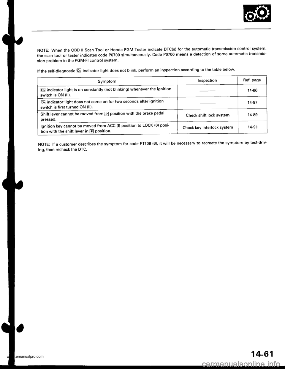
NOTE: When the OBD ll Scan Tool or Honda PGM Tester indicate DTC(s) for the automatic transmission control system'
the scan tool or tester indicates code P0700 simultaneously. code P07oo means a detection of some automatic transmis-
sion problem in the PGM-Fl control system
lf the self-diagnostic E indicator light does not blink, perform an inspection according to the table below.
NOTE: lf a customer describes the symptom for code P1706 (6), it will be necessary to recreate the symptom by test-driv-
ing, then recheck the OTC.
SymptomInspectionRef. page
E indicator light is on constantly (not blinking) whenever the ignition
switch is ON (ll).14-86
E indicator light does not come on for two seconds after ignition
switch is first turned ON (ll).
't 4-41
Shift lever cannot be moved from @ position with the brake pedal
Dressed,Check shift lock system14-89
lgnition key cannot be moved from ACC (l) position to LOCK {0) posi
tion with the shift lever in E position.Check keY interlock system14-91
14-61
www.emanualpro.com