Page 931 of 1395

Bleeding
CAUNON:
. Do not spill brake tluid on the vehicle. it may damage
the paint; if brake fluid does contaqt th€ paint, wash
it otf immodiately with water.
. Maks sure no dirt oy other forsign matter is allowsd
to contaminate the brake fluid.
NOTE:
. Do not reuse the drained fluid.
. Always use Genuine Honda DOT 3 Brake Fluid. Using
a non-Honda brake fluid can cause corrosion and
decrease the life of the svstem.
. The reservoir on the master cylinder must be at the
MAX (upper) level mark at the start of bleeding pro-
cedure and checked after bleeding each brake caliper
and wheel cylinder. Add fluid as required.
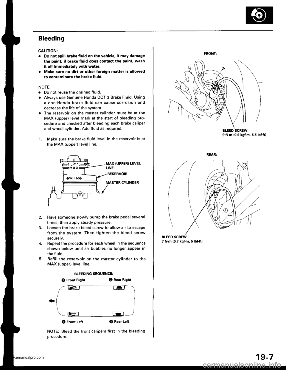
1, Make sure the brake fluid level in the reservoir is at
the MAX (uDDer) level line.
MAX {UPPER) LEVELLINE
RESERVOIR
MASTER CYLINDER
2.
3.
Have someone slowly pump the brake pedal several
times, then apply steady pressu.e.
Loosen the brake bleed screw to allow air to escape
from the system. Then tighten the bleed screw
securely.
Repeat the procedure for each wheel in the sequence
shown below until air bubbles no longer appear in
the tluid.
Refill the reservoir on the master cvlinder to the
MAX (upper) level line.
ALEEDING SEOUENCE:
O Front RightGt Rear Right
O Front LeflO Rear Left
NOTE: Bleed the front calipers first in the bleeding
procedure.
4.
FRONT:
BLEEO SCREW7 N.m (0.? kgf.m, 5 lbf.ftl
19-7
www.emanualpro.com
Page 937 of 1395

Master Cylinder/Brake Booster
Removal/lnstallation
1, Disconnect the brake fluid level switch connectors.
2. Remove the reservoir cap from the master cylinder.
3. Remove the brake fluid from the master cvlinder
reservoir with a syringe.
4. Disconnect the brake lines from the master cylinder.
To prevent spills, cover the line joints with rags or
shop towels.
5. Remove the master cylinder mounting nuts and
wasners.
6. Remove the master cylinder from the brake booster.
CAUTION: Be careful not to bend or damage the
brake lines when removing the master cylinder.
Do not spill brake fluid on the vehicle; it may dam.
age the paint; it brake fluid does cont.ct the paint,
wash it oft immediately with water.
7. Disconnect the vacuum hose from the brake booster.
8. Remove the cotter pin and clevis pin from the clevis.
Do not disconnect the clevis by removing it from
the operating rod of the brake booster. lf the clevis
is loosened, adjust the pushrod length before
installing the brake booster (see page 19-15).
To Front Caliper (Without ABS)
\\
15 N.m {1.5 kgtm, vAcuuM HosE
r r rbf.ft) |
/ | BRAKE FLUTD LEvEL
/l /
swrrcHcoNNEcroRs
/ I I I COTTER PIN
I I / neotace
l,/-- ro Rear wheet cylinders / | I
h ./-''' /. I I IYli //*s (.S
I /r:
9. Remove the four booster mounting nuts.'10. Pull the brake booster forward until the clevis is
clear of the bulkhead.
11. Remove the brake booster from the enqine com-
panment.
12. Install the brake booster and master cylinder in the
reverse order of removal, and note these items:
. When connecting the brake lines, make sure that
there is no interference between the brake lines
and other parts.
. Be careful not to bend or damage the brake lines
when installing the master cylinder.
. lf replacing the master cylinder or brake booster,
check and adjust the pushrod clearance before
installing the master cylinder (see page 19-14).
Fill the master cylinder reservoir, and bleed the
brake system (see page 19-7).
After installation, check the brake pedal height and
brake pedal free play (see page 19-5), and adjust if
necessary.
13 N.m 11.3 kg{.m,I rbf.ft)
13.
14.
To Master Cylinder(Without ABS)To Modulator Unit(with ABs)@-\
\
^ To Front Caliper
9i\.
-#qCLEVIS PIN
):-,/
PROPORTIONING CONTROL VALVE
MASTER CYLINDER
15 N.m (1.5 kgf.m, 11 lbl.ftl
BRAXE BOOSTER
www.emanualpro.com
Page 940 of 1395

Rear Drum Brakes
Never use an air hose or dry brush to clgan brake assemblies,
Use an OSHA approved vacuum cleaner to avoid breathing brake dust.
Contaminated brake linings or drums reduce stopping ability.
Block the front wheels betore iacking up lhe rear ot the vehicle,
Block the front wheels, loosen the rear wheel nuts slightly, then raise the
poned. Remove the rear wheels.
2. Release the parking brake, and remove the rear brake drum.
I N.m {0.9rbr.ft)kgl.m,5.5
\\
\
196
@
Inspection
a
a
rl
a
1.vehicle, and make sure it is securely sup-
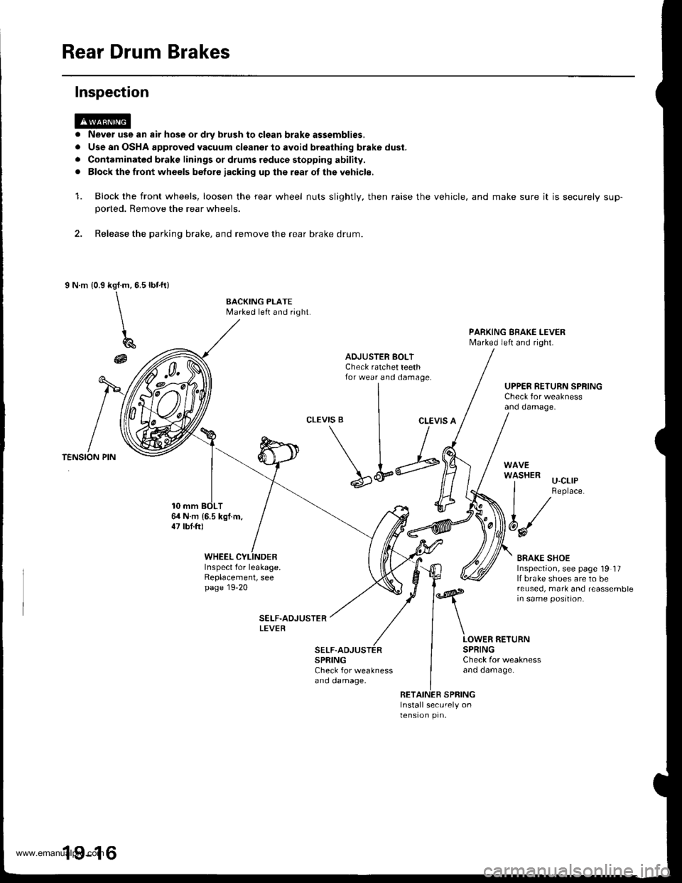
BACKING PLATEMarked left and right.
PARKING EBAKE I-EVERMarked left and right.
ADJUSTER BOLTCheck ratchet teethfor wear and damage.UPPER RETURN SPRINGCheck for weaknessand damage.
CLEVIS BCLEVIS A
64 N.m 16.5 kgl.m,47 lbt.ftl
\L;
SPRINGCheck for weaknessano oamage.
'l-'-' u-cllP
I Replace.
t/
6d/
BRAKE SHOEInspection, see page 19 17lf brake shoes are to bereused, mark and reassemblein same position.
WHEELInspect for leakage.Replacement, seepage 19-20
LOWER RETURNSPRINGCheck for weaknessano oamage.
RETAINER SPRINGInstall securely onlensron prn.
19-16
www.emanualpro.com
Page 942 of 1395

Rear Drum Brakes
Brake Shoes Replacement
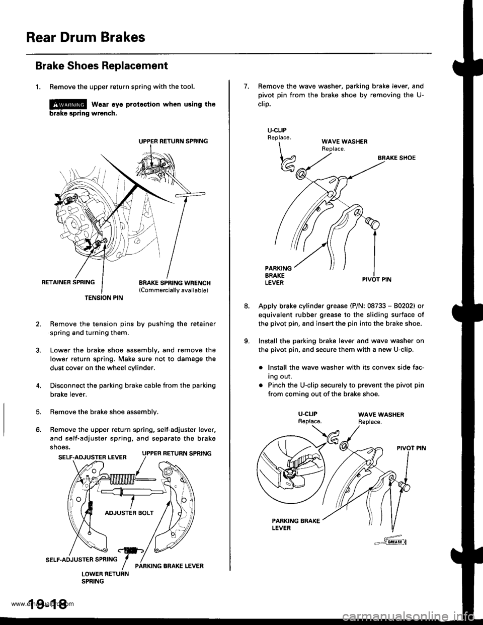
1. Remove the upper return spring with the tool.
l@ w€ar eye protestion when using the
brske spring wrench.
RETAINER SPRINGBRAKE SPRING WBENCH{Commerciallv available)
Remove the tension pins by pushing the retainer
spring and turning them.
Lower the brake shoe assembly, and remove the
lower return spring, Make sure not to damage the
dust cover on the wheel cylinder,
Disconnect the parking brake cable from the parking
brake lever.
Remove the brake shoe assembly,
Remove the upper return spring, self-adjuster lever,
and self-adjuster spring, and separate the brake
shoes.
TENSION PIN
5.
o.
SELF.ADJUSTER LEVER UPPER RETURN SPRING
19-18
7. Remove the wave washer, parking brake lever. and
pivot pin from the brake shoe by removing the U-
cliD.
BRAKE SHOE
Apply brake cylinder grease (P/N: 08733 - 80202) or
equivalent rubber grease to the sliding surface of
the pivot pin, 8nd insert the pin into the brake shoe.
Install the parking brake lever and wave washer on
the pivot pin, and secure them with a new U-clip.
. lnstall the wave washer with its convex side fac-
Ing our.
. Pinch the U-clip securely to prevent the pivot pin
from coming out of the brake shoe.
U.CLIPReplace.
\\
w
U-CLIPReplace.WAVE WASHERReplace.
www.emanualpro.com
Page 944 of 1395

Rear Drum Brakes
Brake Shoes Replacement (cont'd)
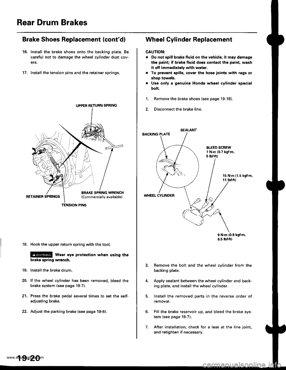
16. Install the brake shoes onto the backing plate. Be
careful not to damage the wheel cylinder dust cov-
ers.
17. Install the tension pins and the retainer springs.
18. Hook the upper return spring with the tool.
@ wsar eye proieclion whon using tho
brtko spring wronch.
lnstallthe brake drum.
lf the wheel cylinder has been removed, bleed the
brake system (see page 19-7).
Press the brake pedal several times to set the self-
adjusting brake.
Adjust the parking brako (see page 19-6).
19.
20.
21.
UPPER RETURN SPRING
TENSION PINS
19-20
7.
SEALANT
Wheel Cylinder Replacement
CAUTION:
. Do not spill brake fluid on th6 vehicle; it may damage
the paint; if brako fluid doos contact tho paint, wash
it off immedialely whh water.
. To pr6v6ni 3pills, cov6r th6 hose ioinls with rags ol
shop lowels,
. Use only a genuine Honda whoel cylinder spocial
bolt.
Remove the brake shoes {see page '19-18).
Disconnect the brake line,
BACKING PLATE
1.
15 N,m 11.5 kgt m,11 tbf.ftl
WHEEL CYLINDER
9 N.m 10,9 kgf'm.6.5 rbtft)
Remove the bolt and the wheel cylinder from the
backing plate.
Apply sealant between the wheel cylinder and back-
ing plate, and install the wheel cylinder.
Install the removed parts in the reverse order of
removal.
Fill the brake reservoir up. and bleed the brake sys-
tem {see page 19-7).
After installation. check for a leak at the line joint.
and retighten if necessary.
www.emanualpro.com
Page 950 of 1395
Component Locations
NOTE: The illustrations show the '97 - 98 models. The '99 - 00 models are similar.
ABS CONTROL UNITRIGHT-REAR WHEEL SENSOR
UNDER.HOOD ABSFUSE/RELAY BOX
RIGHT.FRONT WHEELSENSOR CONNECTOR
RIGHT-FRONTWHEEL SENSORRIGHT-REAB WHEELSENSOR CONNECTOR
MODULATOR UNIT
LEFT.FRONT WHEEL SENSOB
UNDER.DASH FUSE,/RELAY 8OX
UNDER.HOOO FUSE/RELAY AOX
IGl I(, AI FUSE
ABS +B 120 Al FUSEPUMP MOTOR ('II AI FUSE
HOBN/STOP I15 AI FUSE
UNDER.HOOD ABS FUSE/RELAY BOX
LEFT.FRONT WHEELSENSOE CONNECTOR
GAUGE ASSEMBLY
ABS INDICATOR
UNDER-DASH FUSE/NELAY BOX
METER {7.5 AI FUSE
MOTOR RELAY
19-27
SERVICE CHECK CONNECTOR {2PI
D!
trtrtr
[r D!
ABS {7.5 AI FUSEMTR CHECK 17.5 AI FUSE
www.emanualpro.com
Page 951 of 1395
Anti-lock Brake System (ABS)
Features/Construction
When the brake pedal is pressed during driving, the wheels can lock before the vehicle comes to a stop. In such an event,
the maneuverability of the vehicle is reduced if the front wheels are locked, and the stability of the vehicle is reduced if the
rear wheels are locked, creating an extremely unstable condition. The ABS precisely controls the slip rate of the wheels to
ensure maximum grip force from the tires, and it thereby ensures maneuverbility and stability of the vehicle.
The ABS calculates the slip rate of the wheels based on the vehicle speed and the wheel speed, then it controls the brake
fluid pressure to attain the target slip rate.
Grip Force of Tire and Road Surlace
COEFFICIENT OFFRICTION
TARGET SLIP RATE
RADIALOIRECTIONOF THEROTATIONALDIRECTION
SLIP RATE
19-24
www.emanualpro.com
Page 956 of 1395
ABS CONTROL I.]NII {NBK)
Gil
SEFVCE CHEC(STOP
-[rf$-n*'"[m;] t
ra
G2t
rlr*r"t_._*hr;�c, ------ r"-!cc
-
Pf:-tL
t=
#
J*tt-
-
55
V-
,ln l'? g,l,BFN+BsN-,| Br(--o-.8:
Y G101cr02
WIT/BLIJ
,r-,,..J A ^ l0lTA L M|; i trr cor'hrEcroF 'r6P)
8LK
4c1013,402
tG2,
Lffi-
_-- -.^ PMR,
t!94
.,._ PCOM,
9
GRN/8I(x
,,-:gLTpliirn
Ilcrom.:C, IRE^R4iq!AGFNmL---l
BLr( -l
eli -.1
BtK-L,-ry
ABs coNTRoL uNrr 26p coNNEcroR 9E-FY!!(o;fib;;; -- coNNF
e -rlr z :ltl,/ a ,18 e tol/ 12li3l I'
| | 4 1 5 16)17 V I1s V l2' VIIU)4 p91ffi
ABS coNTRoL uNrr 22p coNNEcroR QAIA.Li-;;i,;;) -- coNNE
T
t,*---;T- =l------5o ril mtTlI r, / , | #l,'2 -14 i7 19 -)1 .221 | | ,z
Wire side of lemale terminals
)E CHECK:CTOR (2P)
,f
'97
FRO
TermmateINKcroR (16P)
?'--"r""""-./ 6 ,/ 8\
F{ c7
HEEL SENSOR CONNECTOR
model '98-99 models
NT/ REAR FRONTI RIG-HT-REAR
iTtl /J r lz !\
nal side ol Terminal side olterminals male terminals
LEFT.REAR/nf'�\1./ 1F
r .4-;1V L:JTerminal side ollemale terminals
19-33
www.emanualpro.com