Page 1010 of 1395
Glass
Component Location Index
NOTE: The numbers after the part names show the quantities of the pans used.
Windshield:
MOLOINGUPPER SEAL,2UPPER RUBBER DAM1'00 model)
WINDSHIELDReplacement, page 20-30
LOWER RUBBER DAM('00 model)
UPPER FASTENER('97 - 99 models, and required forreplacement or reinstallationon '00 model)
FASTENER,2(Self'adhesive type, glass side)('97 - 99 models, and required forreplacement or reinstallationon'00 model)
tE-r
*@
FASTENER,2(Self-adhesive-type,
body side)('97 - 99 models, andrequired lor replacementor reinstallation on'00 model)
SIDE RUBBER DAM, 2{'97 -99 models, andrequired for replacementor reinstallation on'00 model)LOWER RUBBER DAMl'97 99 models, and required for reDlacementor reinstallation on'00 modeliOuarter Glass:
OUABTER GLASSReplacement, page 20-35
FASTENER, 1(Clip-type, body side)
\,o,,.,.*,,,
(Self adhesive-type, glass side)
www.emanualpro.com
Page 1013 of 1395
Glass
Windshield Replacement (cont'dl
11. Glue the molding side seal and molding upper seal
to the molding on each side.
20-32
12. Align and glue the molding to the edge of the wind-
shield.
NOTE: Be careful not to touch the windshield
where adhesive will be applied.
a. With a brush, apply a light coat of primer (3lvl N-
200, or equivalent) to the edge ot the windshield
as shown,
b. Glue the adhesive tapes l3M 4212, or equivalent)
to both bottom edges of the windshield.
c. Align the alignment mark on the molding to the
alignment mark of the windshield.
d. Glue the molding to the edge of the windshield.
>: Alignment mark locations
ALIGNMENTApply primerMARK here. ln3ide , /
@
100 mm {3.9 in.l100 mm {3.9 in.}
ADHESIVE TAPEThic*ness: 1.2 mm (0.05 in.)Widthr 4 mm (0.16 in.)
r0 mm (1.6 in.l
www.emanualpro.com
Page 1014 of 1395

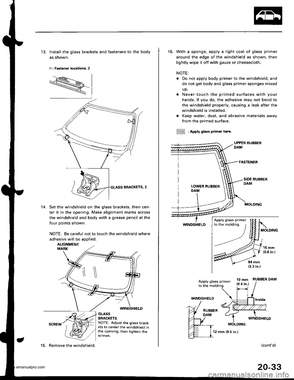
'13. Install the glass brackets and fasteners to the body
as shown.
>: Fastener locations, 2
R-
14. Set the windshield on the glass brackets. then cen
ter it in the opening. Make alignment marks across
the windshield and body with a grease pencil at the
four points shown.
NOTE| Be careful not to touch the windshield where
adhesive will be applied.
ALIGNMENTMABK
WINDSHIELD
GLASSBRACKETSNOTE: Adjust the glass brack-ets to center the windshield inthe opening, then tighten the
15. Remove the windshield.
12 mm 10.5 in.)
16. With a sponge, apply a light coat of glass primer
around the edge of the windshield as shown, then
lightly wipe it off with gauze or cheesecloth.
NOTE:
Do not apply body primer to the windshield, and
do not get body and glass primer sponges mixed
up.
Never touch the primed surfaces with your
hands. lf you do, the adhesive may not bond to
the windshield properly, causing a leak after the
windshield is installed.
. Keep water, dust, and abrasive materials away
from the primed surface.
//fu : Apply glass ptimar hea.
WINDSHIELD
10 mm{0.4 in.}RUBBER DAMApply glass primerto the molding.
(cont'd)
20-33
Apply glass primer
WINDSHIELD
MOLDING
www.emanualpro.com
Page 1018 of 1395
7. Glue the fastener to the inside face of quarter glass
as shown. lf the old quarter glass is to be reinstalled,
apply a light coat of primer (3M C- 100, or equivalent),
then apply butyltape to the quaner glass as shown.
NOTE:
. Be careful not to touch the quarter glass where
adhesive will be aDplied.
. Do not peel the separator off the butyl tape.
Width: 5.4 mm 10.25 in.)
BUTYL TAPE
I
w-mr
>t\
/\SS MOLDING
/'/.//// | Bttryl taee locations l3M 8628, or equivalent)Thickness:3.2 mm 10.13 in.l
>: Fastenoa location, I
FASTENER MOLDING
GLA
8. lnstall the fastener to the bodv as shown.
>: Fastener location, 1
1l mm(0.43 in.)
GLASS
400 mm (15.75 in.)
9. lf the old quarter glass is to be reinstalled, seal the
body hole with piece of urethane tape, Set the quar
ter glass upright in the opening and make alignment
marks across the quarter glass and body with a
grease pencil at the three points shown.
(cont'd)
20-37
ALIGNMENT MANK
10. Remove the quarter glass.
www.emanualpro.com
Page 1021 of 1395
lnterior Trim
20-40
CARGO FRONTSPACER(see page 20 43)
FRONT PILLARTRIM(see page 20-41)
TRUNK FLOOREXTENSION(see page 20 43)
HEADLINERRemoval and lnstallation,page 20-44
Component Location Index
SRS components are located in the areas marked with an asterisk (*). Review the SRS component locations, precautions,
and procedures in the SRS section (24) before performing repairs or service.
CENTER PILLARUPPER TRIM(see page 20 41)CENTER PILLARLOWER TRIM PANEL(see page 20 41)
FRONT SIDETRIM(see page 20-41)
BEAR SIDETEIM(see page 20'41)
OUARTER PILLARTRIM PANEL(see page 20 42)
*CARPET
Replacement,page 20 45
CENTER CONSOLE IM/T}Replacement, page 20-47
CENTEN TABLE(see page 20-45)
PARKING BRAKECOVER(see page 20-45)
TRIM
www.emanualpro.com
Page 1022 of 1395
Removal and Installation
CAUTION:
. Put on gloves to protect your hands,
. When prying with a tlat-tip screwdrivel, wrap it with protective tape to prevent damage.
. When removing the support strut of the rear hatch glass, you will need to open or close the rear hatch glass by hand.
NOTE: Take care not to bend or scratch the trim and panels.
>: Clio locations
a>,5c>, 1o>.2e>,2B >,8
UPPERBOLT7/16 - 20 UNF32 N.m {3.3 kgf.m,24 rbt.ft)Apply liquid thread
CENTER PILLARLOWER TRIM PANEL
LOWERANCHOBCOVER('98 00 models)
{cont'd)
I l_lss-l , | 'rrl
elElw"lel sl
FRONT SEAT BELT
FRONT SEAT BELLOWER ANCHORBOLT7/15 - 20 UNF32Nm(3.3kgf.m,24 tbt.ftl
ANCHORCAP('97 model)
REAR DOORTRIM
REAR SIDE TRIMtlemove the rear seat(see page 20 63).
REAR SIDE
20-41
www.emanualpro.com
Page 1024 of 1395
>: Bolt, screw locations
a>,3 B>,4
o: Nut locations, 2 >: Clip locations
TRUNK MAT
CARGO STORAGE BIN
/ rr. 6xl.Omm I
m)b D lbe.8 Nm r1.o ksnm.l-
c>,2 0>,2 A>,8 B>,r
| .€ | r- -I At I tl1|r' t I l���'---llH- | E
GlrrIIITTpl 0pE l w I l--Tr@HPv | | v I vv
LOCK ASSEMBLY
TRUNK FLOOREXTENSIONS
FLOOR SrO€LID
FLOOR SIDE FRAME
CARGO FRONT TRIM
Insta,lation is the reverse of the removal procedure.
NOTE:
. lf necessary, replace any damaged clips.
r Before installing the anchor bolts, make sure there are no twists or kinks in the seat belts.
BUSHING
l^IV
>ilv '%L
"ro"*i*
CARGO AREA FLOOR
l*,hl
20-43
www.emanualpro.com
Page 1025 of 1395

lnterior Trim
Headliner Removal and Installation
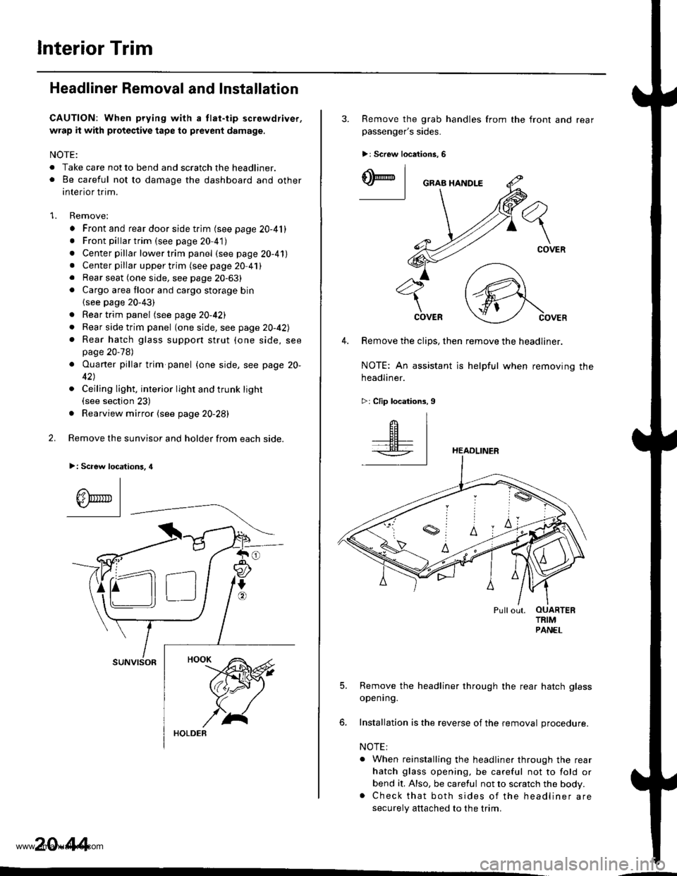
CAUTION: When prying with a tlat-tip screwdriver,
wrap it with protective tape to prevent damage.
NOTE:
. Take care not to bend and scratch the headliner.o Be careful not to damage the dashboard and other
interior trim.
1. Remove:
. Front and rear door side trim (see page 20-41). Front pillartrim (see page 20-41)
. Center pillar lower trim panel (see page 20-41). Center pillar upper trim (see page 20 41). Rear seat (one side, see page 20-63). Cargo area floor and cargo storage bin
{see page 20-43)
. Rear trim panel (see page 20-421
. Rear side trim panel (oneside, see page 20-42l,
. Rear hatch glass support strut (one side, seepage 20-78)
. Ouaner pillar trim panel {one side, see page 20-
42)
. Ceiling light, interior light and trunk light(see section 23)
. Rearview mirror (see page 20-28)
2. Remove the sunvisor and holder from each side.
>: Scaew location3, 4
I
A\"r- |Yr* || -
suNvtsoR
20-44
3. Remove the grab handles from
passenger's sides.
>r Screw locations, 6
the front and rear
ry_l
COVER
4. Remove the clips, then remove the headliner.
NOTE: An assistant is helpful when removing the
headliner.
>: Clip locations,9
HEADLINER
Pullout. OUARTERTRIMPANEL
5. Remove the headliner through the rear hatch glass
openrng.
6. Installation is the reverse of the removal procedure.
NOTE:
. When reinstalling the headliner through the rear
hatch glass opening, be careful not to fold or
bend it, Also, be careful not to scratch the body.. Check that both sides of the headliner are
securely attached to the trim.
www.emanualpro.com