1998 HONDA CR-V 11-142
[x] Cancel search: 11-142Page 204 of 1395

Fuel and Emissions
Special Tools ...................... 11-2
Component Locations
lndex ...................... ....,.... 11-3
Svstem Description
Vacuum Connections ...........,....,.,................. 1 1-9
Electrical Connections ................................... 1 1-15
System Connectors .,.,,.,............................,.,. 1 1-36
Troubleshooting
Troubleshooting Procedures,.,..................... 11-60
Engine Control Module/Powertrain ConttolModule Terminal Arrangement .............., 11-67
Diagnostic Trouble Code Chart .................... 1 t-75
How to Read Flowcharts .......,.....,.,............... I 1-79
PGM-Fl System
System Description .................,.,.,,,............... 1 1-80
Troubleshooting Flowcharts
Engine Control Module/PowertrainControl Module ........11-52
Manifold Absolute Pressure Sensor ............. 11-90
Intake Air Temperature Sensor .................... 1 1-95
Engine Coolant Temperature Sensor .,..,.,.... 1 1-99
Throttle Position Sensor ...........,.....,.,.,..,...... I 1'103
Primary Heated Orygen Sensor (Sensor 1) ... 11-110
Secondary Heated Oxygen Sensor{Sensor 2l .................. 1 1-117
Heated Oxygen Sensor Heater ..................... 11-121
Fuef Supply System ......11-124
Random Misfire ,....,.,..... 11-126
Mistire Detected in One Cylinder .....-........... 11-128
Knock Sensor ................ 11-130
CKP/TDC/CYP Sensor .................................... 1 1-131
Vehicle Speed Sensor ...............................,.... 1 1-135
Barometric Pressure Sensor .....,...,...,.,,........ 1 1-137
Electrical Load Detector ...,.,.......................... 1 1-138
CKF Sensor ................,.,, '11-112
ECM/PCM lnternaf Circuit ............................. 11'117
HO2S Replacement .,.,.,. 11-148
ldle Control System
System Description ............ 11-149
Troubleshooting Flowcharts
ldle Control System ...... 11-150
fdle Air Control Valve ......................,............. 11-152
Air Conditioning Signal ................................. I 1-155
Alternator FR Signal ...................................... 1 1-159
Starter Switch Si9na1 .................................... t l-161
Power Steering Pressure Switch Signal ...... 11-162
Brake Switch Si9na1 ...................................... 11-166
Fast ldle Thermo Valve .,.,.............................,.,.,. 11-168
ldle speed setting .............. 11-169
Fuel Supply System
Fuel Lines ............................ 11-171
Fuef Tube/Ouick-Conneci Fittings ..................... 11 -175
System Description ............ 11-178
Fuel Pressurg ...................... 11-178
Fuel Iniectors ................,..... 11-179
Fuel Pressure Re9u1ator .............................,.,...., f 1-181
Fuef Fifter ....,.,.,.,,,,.,............11-142
Fuel Pump ........................... 11-183
Fuel Gauge .......................... 11-184
Fuel Gauge Sending Unit ................................... I 1-185
Low Fuel Indicator System ...........,.,..,............... 1 1-185
PGM-FI Main Relay ............. 11-187
Fue|Tank................ ............. 11-191
Intake Air System
System Description ............ 11-193
Air Cleanel ,.,.,..................... 11-194
Throttle Cable ..................... 11-194
Throttle Body........ .............. 11-196
Emission Control System
System D$cription ...,....,.,. 11-199
Tailpipe Emission ............... 11-199
Three Way Catalytic Converter ..................,.,...,, 11-199
Positive Crankcase Ventilation System .,.,,,,.,.., 11-2O1
Evaporative Emission Controls .........,.,.,............ 11-203
www.emanualpro.com
Page 280 of 1395

Troubleshooting
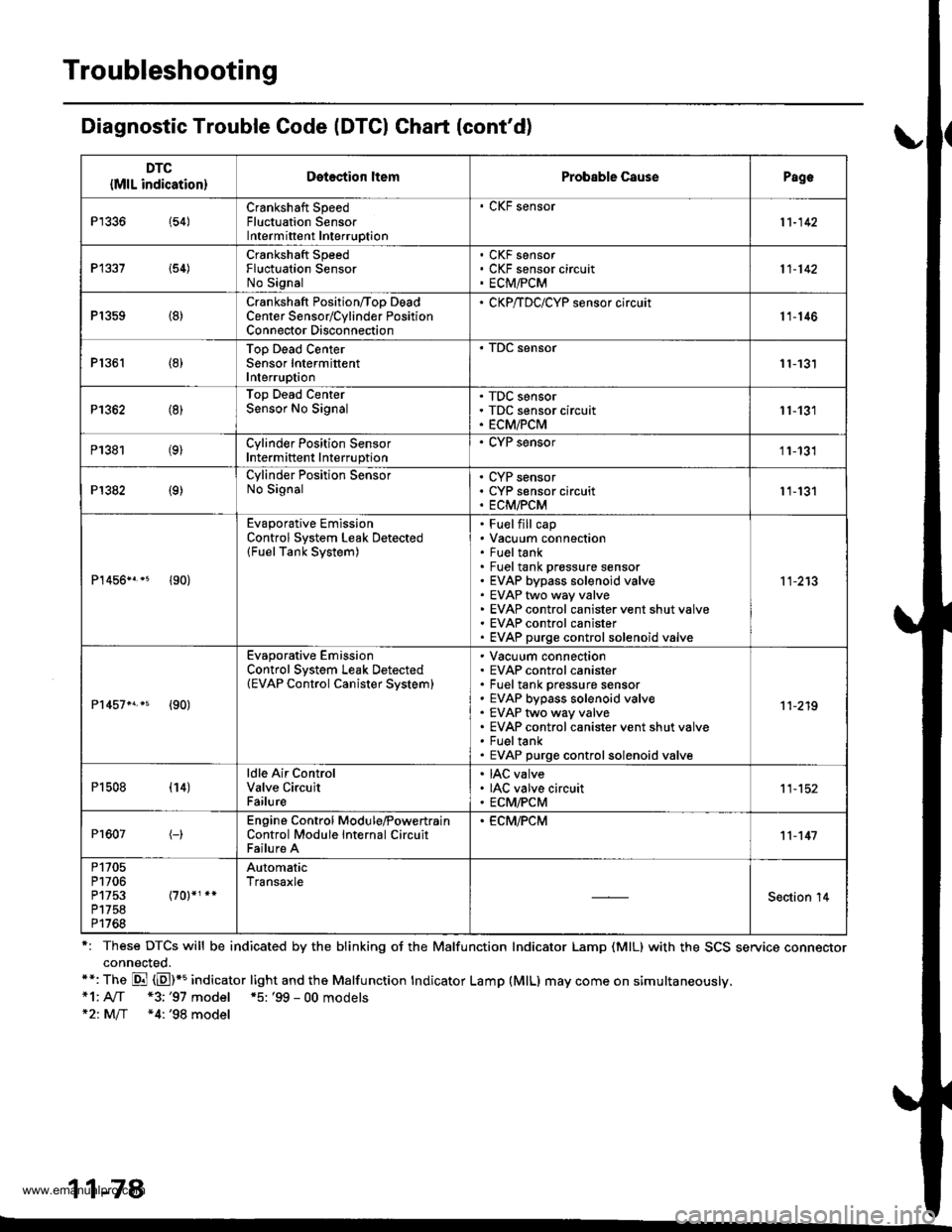
Diagnostic Trouble Code (DTCI Ghart (cont'd)
r: These DTCS will be indicated by the blinking oJ the Malfunction Indicator Lamp (MlL) with the SCS service connectorconnected.**: The Di (E)*5 indicator light and the Malfunction tndicator Lamp (MlL) may come on simultaneously.*1: A[f *3;'97 model *5: '99 - 00 models*21M/f *4: '98 model
11-78
DTC
{MlL indication}Detection ltemProbable CausePagc
P1336 154)Crankshaft SpeedFluctuation SensorIntermittent Interruption
. CKF sensor
11-142
P1337 i54)Crankshaft SpeedFluctuation SensorNo Signal
CKF sensorCKF sensor circuitECM,FCM11-142
P1359 (8)Crankshaft Position/Too DeadCenter Sensorrcylinder PositionConnector Disconnection
' CKP/TDC/CYP sensor circuit11-146
P1361 (8)Top Dead CenterSensor IntermittentInterruption11-131
P1362 (8)Top Dead CenterSensor No SignalTDC sensorTDC sensor circuitECM/PCM11-131
P1381 (9)Cylinder Position SensorIntermittent Interruption
. CYP sensor11-131
P1382 (9)Cylinder Position SensorNo SignalCYP sensorCYP sensor circuitECM/PCM11-131
P1456n.* {90}
Evaporative EmissionControl System Leak Detected(FuelTank System)
Fuelfill capVacuum connectionFueltankFuel tank prossure sensorEVAP bypass solenoid valveEVAP two way valveEVAP control canister vent shut valveEVAP control canisterEVAP purge controlsolenoid valve
11-213
Pr457n.s {90)
Evaporative EmissionControl System Leak Detected(EVAP Control Canister Svstem)
Vacuum connectionEVAP control canisterFuel tank pressure sensorEVAP bypass solenoid valveEVAP two way valveEVAP control canister vent shut valveFueltankEVAP purge controlsolenoid valve
11-219
P1508 (14)ldle Air ControlValve CircuitFailure
IAC valveIAC valve circuitECM/PCM11-152
Pr607(-)Engine Control Module,PowertrainControl Module Internal CircuitFailure A
. ECM,FCM11-147
P1705P1706P1753P1758P1768
AutomaticTransaxle
Section '14
www.emanualpro.com
Page 344 of 1395

PGM-FI System
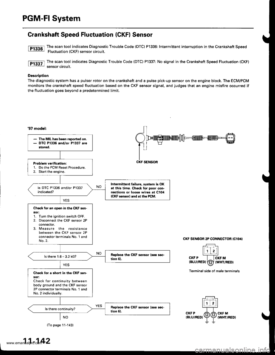
Grankshaft Speed Fluctuation (CKF) Sensor
fF13361l Tj":""l.tool indicates Diagnostic Trouble Code (DTCI P1336: Intermittent interruption inthe Crankshaft Speed: Fluctuation (CKF) sensor circuit.
The scan tool indicates Diagnostic Trouble Code (DTC) P1337: No signal in the Crankshaft Speed Fluctuation (CKF)
sensor circuit.
Description
The diagnostic system has a pulser rotor on the crankshaft and a pulse pick-up sensor on the engine block. The ECM/PCM
monitors the crankshaft speed fluctuation based on the CKF sensor signal, and judges that an engine misfire occurred if
the fluctuation goes beyond a predetermined limit.
37 mod.l:
CKF SENSOR 2P CONNECTOR IClO4I
T:]l-r'r Lll
l1 zLl''''CKF P I lcKF Mtalu/aeot fdJ twxrneor\-7
Terminal side of male terminals
(To page 11-113)
11-142
- Tho MIL ha3 been reported on.- DTC P1336 and/or P1337 arestored.
Problem verificrtion:1. Do the PCM Reset Procedure.2. Start the engine.
Intermittent {ailure, systom is OK.l thia timo. Ch6ck tor poor con-nections or loose wir$ at ClorlICKF sonsorl .nd at tho PCM.
Chock tor an opon in th6 CKF .en'30r:1. Turn the ignition switch OFF.2. Disconnect the CKF sensor 2Pconnector,3, M easure the resistancebetween the CKF sensor 2Pconnector terminals No. 'l andNo.2.
ls there 1.6-3.2 kO?
Check fo. a short in the CKF 3en-sot:Check for continuity betweenbody ground and the CKF sensor2P connector terminals No. 1 andNo.2 individually.
CKF SENSOR
www.emanualpro.com
Page 345 of 1395

{From page 11-142)
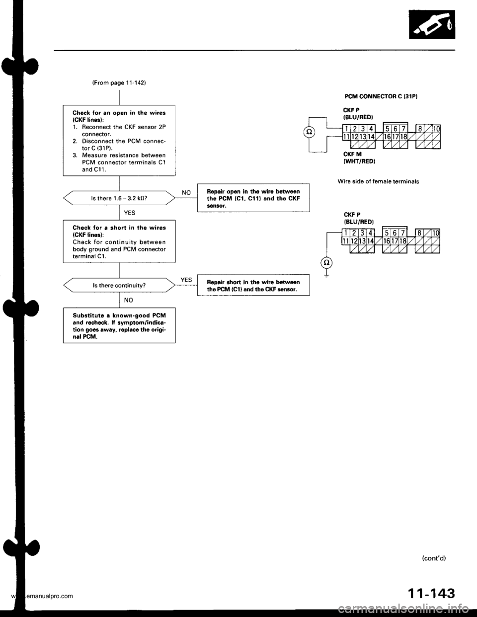
Chock to. an open in the wires(CKF lin06l:1. Reconnect the CKF sensor 2Pconnector,2. D;sconnect the PCM connec-tor C (31P).
3. Measure resistance betweenPCM connector terminals C1and Cl1.
Ropair open in the wire betwoontho PCM lcl, Cl1l and th6 CKF!6naor.ls there 1.6 - 3.2 k0?
Chock tor a short in the wires(CKF lino3):Check for continuity betweenbody ground and PCM connectorterminalCl.
Rcoair short in thc wire b€tweenthe PCM {Cl I and the CKF .en!o..
Subsiituto r known-good PCMand r6chock. lf symptom/indica-tion goe3 away, roplaco the origi-n.l rcM.
PCM CONNECTOR C 13lPI
Wire side of lemale terminals
CKF P
IELU/REDI
(cont'd)
11-143
www.emanualpro.com