Page 702 of 1395

End Cover
Removal
NOTE:
o The illustration shows the 4WD automatic transmission; the 2WD is similar.. cleanall parts thoroughly in solvent or carburetor cleaner, and drythem with compressed air.. Blow out all passages.
. When removing the transmission end cover, replace the following:- End cover gasket- Lock washer- O-rings- Shaft locknuts- Conical spring washers- Sealing washers
END COVER GASKET
MAINSHAFT LOCKNUT
CONICAL SPRING WASHER
6 x 1 .0 rhm EOLTS
PARK PAWL
A/T GEAR POSMONSwlTCH COVER
NEEDI.T BEARING
SUB.SHAFT LOCKNUT
CONICAL SPRINGWASHER
LINE AOLT
ATF COOI.f B LINES
14-186
PAwL 7// Locx wASHER
'sHAFr 9/ ?ARK srop
o-- Ay' couNTERsHAFr
G-€ LocKNUr!€ / ..t,"o, "oo
A/T GEAR POSMONSW|TCH HARNESS CLAMP
CONICAL SPRINGWASHCR
A/T GEAR POSITION
PARK GEAR
Y CLUTCH
lST GEAR
NEEDLE BEARING
1ST CLUTCH ASSEMBLY
THRUST WASHER
THRUST NEEDLE AEARING
O.RINGS
\\
SUB.SHAFT 1ST GEAR
MAINSHAF? 'ST GEAR
MAINSHAFT 1STGEAR COLLAR
SEALING WASHERS
!€'-l
I"EVERSPRING
COUNTERSHAFTlST GEAR COLLAR
PAWL
lt1/ sroe
Y plwl f
L/'SPRING
LOCKNUT
LINE BOLTSEALING WASHERS
www.emanualpro.com
Page 703 of 1395

1. Remove the A/T gear position switch harness
cramp.
Remove the y'VT gear position switch cover.
Remove the bolt securing the ly'T gear position switch
harness clamp on the end cover, then remove the A/T
gear position switch.
Remove the 12 bolts securing the end cover. then
remove the cover.
Slip the special tool onto the mainshaft as shown.
6. Engage the park pawl with the park gear.
7. Cut the locktabs of each shaft locknut using a chisel as
shown. Keep all chiseled particles out of the transmis-
ston.
M=tt"
Align the hole of the sub-shaft 1st gear with the hole
of the transmission housing. then insert a pin to lock
the sub-shaft while removing the sub-shaft locknut.
Remove the locknuts and conical spring washers from
each shaft.
NOTE:
Mainshaft and countershaft locknuts have left-
hand threads.
Clean the old countershaft locknut. lt is used to
install the press fit park gear on the countershaft.
MAINSHAFT
PIN8 mm pin,
commercially
SUB-SHAFTLOCKNUTReplace.COUNTERSHAFTLOCKNUTReplace.
CONICAL SPNING WASHERSReplace.
9. Remove the lock pin that was installed to hold the
sub-shaft.
10. Remove the special tool from the mainshaft.
11. Remove the 1st clutch, mainshaft 1st gear assembly,
and mainshaft 1st gear collar.'12. Remove the sub-shaft 1st gear.
13. Remove the park pawl, pawl spring, pawl shaft. and
pawl stoP.
14. Remove the park lever from the control shaft.
15. Using a universal two jaw puller, remove the park
gear, one-way clutch, and countershaft 1st geal
assemblv.
{Commercially available)
1SY GEAR
Remove the needle bearing and countershaft 1st gear
co ar.
Remove the ATF cooler lines,
LOCKNUTReplace.
2\
Irot)
PULLER
11.
14-187
www.emanualpro.com
Page 718 of 1395

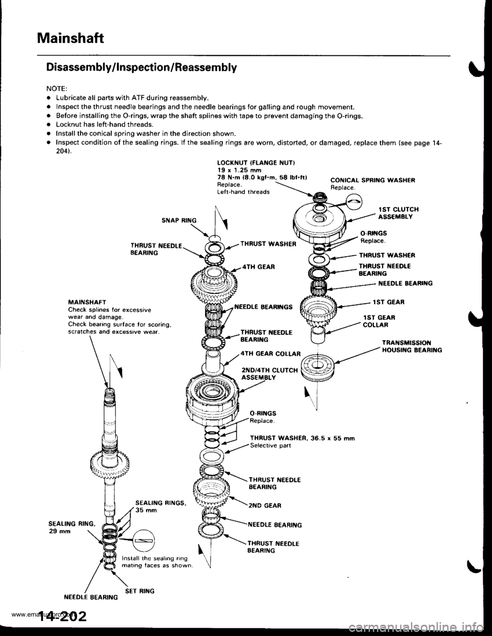
Mainshaft
Disassembly/lnspection/Reassembly
NOTE:
. Lubricate all parts with ATF during reassembly.
.Inspectthethrustneedlebearingsandtheneedlebearingsforgallingandroughmov\
ement,
. Before installing the O-rings. wrap the shaft splines with tape to prevent damaging the O-rings.. Locknut has left-hand threads.
. Install the conical spring washer in the direction shown.
. Inspect condition of the sealing rings. lf the sealing rings are worn, distorted, ordamaged, replace them (see page 14-
2041.
LOCKNUT IFLANGE NUT)19 x 1.25 mm78 N.m {8.O kgf.m,58 lbl.ftlReplace.Left-hand threads
CONICAL SPRING WASHERReplace.
lST CIUTCHASSEMBI.YSNAP RING
THRUST NEEDLEB€ARING
Install the sealing ringmating faces as shown
THRUST WASHEB
4TH GEAR
BEARII{GS
o-Brr{Gs
o-Rtt{GsReplace.
THRUST WASHCR
THRUST NEEOI€BEARIl{G
I{EEDLE BEARIIIG
lST GEARMAINSI{AFTCheck splines for excessivewear ano damage.Check bearing surface tor scoring,scratches and excessive wear.
rST GEARCOLLARTXBUST 1{EEDLEBEARIl{G
4TH GEAR COLLAR
2ND/4TH CLUTCX
TnANSMtSSIOt{HOUSII{G BEARII{G
THRUST WASHER, 36.5 r 55 mmSelective part
SEALING29 mm
THRUST NEEDLESEARING
2NO GEAR
NEEDLE EEARING
THRUST NEEDI-EBEARING
RltrlG,
NEEDLE EEARING
14-202
SET RING
www.emanualpro.com
Page 719 of 1395
Inspection
Clearance Measurement
1. Remove the mainshaft bearing from the transmis-
sion housing lsee page 14-227l..
2. Assemble the mainshaft parts, but do not install the
O-rings,
CONICAL SPRING WASHER
SNAP RII{G
lST CLUTCH ASSEMELY
THRUST WASHER
1ST GEAB COLLAR
TRAI{SMISSIONHOUSIf{G BEARING
THRUST WASI{ER
2[{D/4TH CLUTCHASSEMALY
GEAR COLLAR
THRUST WASHER.5r55mmSelective part
THBUST IIEEDLEEEARII{G
2ND G€AR
EEARIt{G
TI{RUST NEEOLEBEARII{G
MAII{SHAFT
3. Tighten the mainshaft locknut to 29 N.m (3.0 kgf.m,
22 tbf.ft).
The mainshaft locknut has left-hand threads.
29 N.m (3.O kst.m, 22 lbt.frl
Hold 2nd gear against the 2nd clutch, then measure
the clearance between 2nd gear and 3rd gear with a
feeler gauge. Take measurements in at least threeplaces, and use the average as the actual clearance.
STANDARD: 0.05 - 0.13 mm (0.002 - 0.005 in)
FEELER GAUGC
THRUST WASHER.36.5 x 55 mm
(cont'd)
3RD GEAR 2'{D GEAR
14-203
www.emanualpro.com
Page 721 of 1395
Countershaft
Disassembly/lnspection/Reassembly
NOTE:
. Lubricate all pans with ATF before reassembly.
.Inspectthethrustneedlebearingsandtheneedlebearingsforgallingandroughmov\
ement.
. Before installing the O-rings, wrap the shaft spllnes with tape to prevent damaging the O-rings.
. Locknut has left-hand threads.
. Install the conical spring washer in the direction shown.
R€VERSE GEAR
LOCKNUT IFLANGE NUTI23 x 1.25 mm103-0-103N.mCONICAL SPRINGWASHERReplace.t10.5 - 0 -
75.9 - 0 -
Replace.
10.5 kgl.m,75.9 lbt.lr)
Lelt.hand threads
COUNTERSHAFTCheck splines for excessivewear and damage.
REVERSE SELECTORHUB
4TH GEAR
NEEDLE EEARING
NEEOLE BEARING
REVERSESELECTOR
OISTANCE COLLAR.28 mmSelective part
2NO GEAR
lST GEAR
I{EEDLE BEARINGCheck bearing surface for scoring,scratches and excessive wear.lST GEAR COLLAR
TRANSn SSTONHOUSI G BEARING
3RD GEAR
NEEDLE BEARING
3RD GEAR COLLAR
THRUST NEEOLE BEARING
SPLINED WASHER
3RO CLUTCH ASS€MBLY
14-205
www.emanualpro.com
Page 724 of 1395

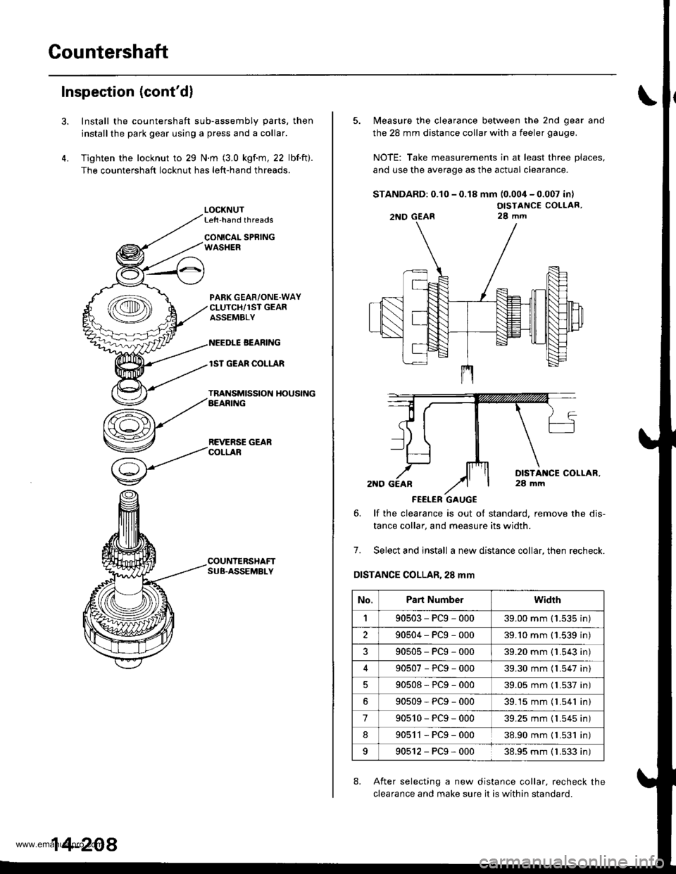
Countershaft
Inspection (cont'd)
3.
4.
Install the countershaft sub-assembly parts, then
installthe park gear using a press and a collar.
Tighten the locknut to 29 N.m (3.0 kgf.m, 22 lbf.ft).
The countershaft locknut has left-hand threads.
LOCKNUTLe{t-hand threads
CONICAL SPRINGWASHER
PABK GEAR/ONE.WAYCLUTCH/1ST GEARASSEMBLY
NEEDLE BEANING
lST GEAR COLLAR
TRANSMISSION HOUSINGAEARING
REVERSE GEARCOLLAR
COUNTERSHAFTSUB.ASSEMBLY
14-208
5. Measure the clearance between the 2nd gear and
the 28 mm distance collar with a feeler gauge.
NOTE: Take measurements in at least three places,
and use the average as the actual clearance.
STANDARD: 0.10 - 0.18 mm (0.004 - 0.007 in)
OISTANCE COLLAR,28 mm
FEELER GAUGE
6. lf the clearance is out ot standard, remove the dis-
tance collar, and measure its width.
7. Select and install a new distance collar, then recheck.
DISTANCE COLLAR,28 mm
8. After selecting a new distance collar. recheck the
clearance and make sure it is within standard.
2NO GEAR
No.Part Numberwidrh
190503-PCg-00039.00 mm ('1.535 in)
290504-PCg-00039.'10 mm (1.539 in)
?90505-PCg-00039.20 mm {1.543 in)
90507-PCg-00039.30 mm (l.547 in)
90508*PCg-00039.05 mm (l.537 in)
90509-PCg-00039.15 mm (l.541 in)
790510-PCg-00039.25 mm {1.545 in)
890511-PCg-00038.90 mm { L531 in)
990512-PCg-00038.95 mm ( 1.533 in)
www.emanualpro.com
Page 749 of 1395

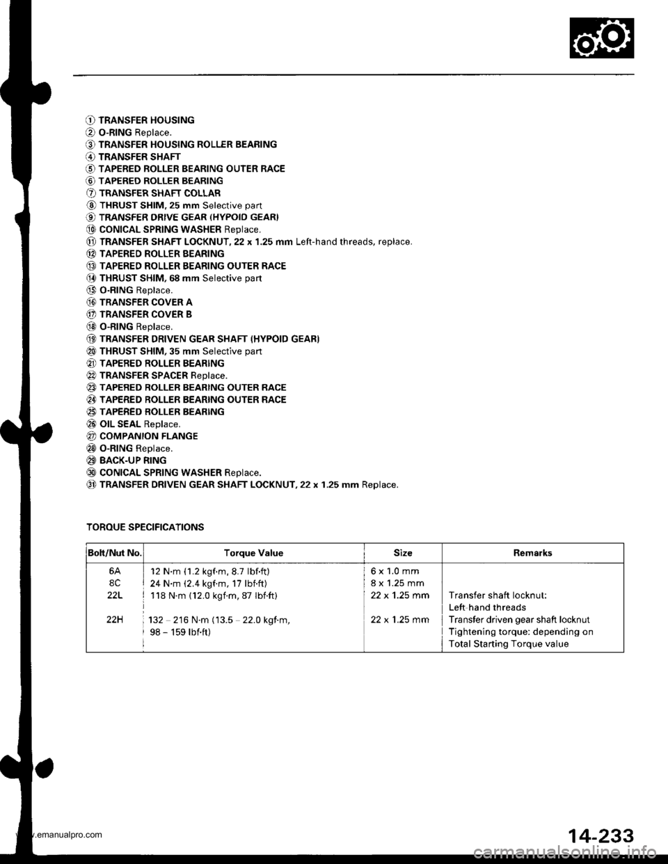
O TRANSFER HOUSING
O o-RING Replace.
O TRANSFER HOUSING ROLLER BEARING
@ TRANSFER SHAFT
O TAPERED ROLLER BEARING OUTER RACE
@ TAPERED ROLLER BEARING
O TRANSFER SHAFT COLLAR
@ THRUST SHIM, 25 mm Selective part
€) TRANSFER DRtvE GEAR (HYPoID GEAR}
@ coNtcAL SPRtNG WASHER Reptace,
@ TRANSFER SHAFT LOCKNUT,22 x 1.25 mm Left-hand rhreads, replace.
(D TAPERED ROLLER EEARING
@ TAPERED ROLLER EEARING OUTER RACE(} THRUST SHIM, 68 mm Selective part
@ O-RING Replace.
@ TRANSFER coVER A
(} TRANSFER COVER B
@ o-RING Replace.
(9 TRANSFER DRIVEN GEAR SHAFT (HYPOID GEAR)
@ THRUST SHIM, 35 mm Selective part
@ TAPERED ROLLER BEARING
@ TRANSFER SPACER Reptace.
@ TAPERED RoLLER BEARTNG OUTER RACE
@ TAPERED ROLLER BEARING OUTER RACE
@ TAPERED BOLLER BEARTNG
@ olL SEAL Replace.
@ COMPANION FLANGE
@ o-RING Replace.
@ BACK-UP RING
@ coNtcAL SPRtNG WASHER Reptace.
@ TRANSFER DRIVEN GEAR SHAFT LOCKNUT,22 x 1.25 mm Replace.
TOROUE SPECIFICATIONS
Boh/Nut No.Torque ValueSizeRemarks
6A
8C
22L
22H
12 N'm (1.2 kgf.m,8.7 lbf.ft)
24 N.m (2.4 kgf.m, 17 lbnft)
118 N.m (12.0 kgim,87 Ibift)
132 216 N.m (13.5 22.0 kgf.m,
98 - 159 lbift)
6x1.0mm
8 x 1.25 mm
22 x 'l.25 mm
22 x 1.25 mm
Transfer shaft locknut:
Left hand threads
Transfer driven gear shaft locknut
Tightening torque: depending on
Total Starting Torque value
14-233
www.emanualpro.com
Page 751 of 1395
Disassembly
1. Remove the transfer covers A and B.
2. Cut the lock tabs of the locknut usino a chisel.
LOCK TAB
5.
Put a 14 mm Allen wrench in the gear side of the
transfer shaft, then secure the Allen wrench in a
bench vise.
Remove the transfer shaft locknut and the conical
spring washer. The transfer shaft locknut has left
hand threads.
Remove the transfer shaft, transfer drive gear, 25
mm thrust shim, transfer shaft collar, and tapered
roller bearing from the transfer housing.
TRANSFER SHAFT
THRUST SHIM,25 mrnSelective part
CONICAL SPRINGWASHERReplace.
(cont'd)
1a mm ALLEN WRENCH
14-235
www.emanualpro.com