1998 HONDA CIVIC sound
[x] Cancel search: soundPage 362 of 2189
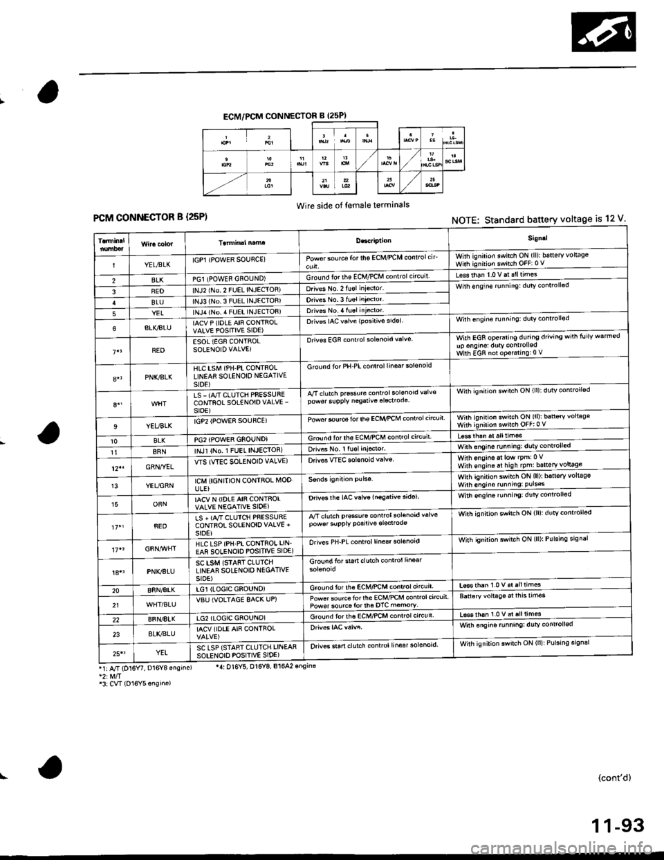
ECM/PCM CONNECTOR B (25PI
Wire side of female terminals
FCM CONNECTOR B {25P)NOTE: Standard battery voltage is 12 V
Sign.l
YELtsLKIGP1 IPOWER SOUflCE)Powor sou rca for the ECM/PCM conlrolcirwhh ignilion swilch ON (ll)ibatteryvoltageWith ignition switch OFF:0 V
BLKPGl {POWEB GNOUND)Ground fo. the ECM,/PCM contrclcncuit'Less than 1.0 V at slltimes
FEDlNJ2 (No 2 FUEL INJECIOR)Drives No. 2 fu€l inieclor'Wirh enqine runnin9: dulv conlroll6d
BLUlNJ3 (No.3 FUEL INJECTOB)Orives No.3 fuel inieclor'
YELlNJ,r lNo. 4 FUEL INJECTOF)Drives No. 4 luel injector'
6BLI(BIUIACV P (IDLE AIR CONTROLVAIVE POSITIVE SIDE)O.iv€s IAC valve {Posirivo side)Wilh engine running: duty conrrollod
BEDESOL {EG8 CONTROLSOLENOID VALVE)Drives EGF controlsolonoid valveWith EGR operaiing during driving wirh follv warmedup onginsl dutY controlledWilh EGR nol op€r.ring:0 V
PNKSLKHlC tstvr (PH-PL CONTnOLLINEAfl SOLENOID NEGATIVEst0E)
G rcund for PH-PL control linsar solsnoid
8.,LS - (A/T CLUTCH PFESSURECONTROL SOTENOIDVALVE'sroE)
A/Tclutch prsssure conrrol sol€nod valv€pow6r slpply negative elecrodeWith ignilion swirch ON (ll):dutv controll€d
9YEUBLKrGP2 {POWE8 SOUFCE)Powor $urce for lhe ECI{,'PCM controlc'rcuitwnh ignirion swirch ON (ll): ban€ry voltag€with ignirion swnch oFF:0 v
10BLKPG2IPOWER GSOUNDIGround lor ths ECM/PCM controlctrcuil
118RNINJl {No,1 FUEL INJEqIOR)orives No. r ru6l Iniocror.With onsino at low lpm:0Vwith ens,n. ar hish tpm:bsneryl9!9gl-12"GRN,.YELWS (WEC SOLENOID VALVE)Orivos WEC solanoid v.lvs.
13YEUGRNICM {I6NITION CONTROL MODULE}
With ignition switch ON (ll)r b5n6ry volt€gsWilh engino running: Puls6
15ORNIACV N (IDLE AIN CONTSOIVALVE NEGATIVE SIOE)Drivos the IAC valve lnogativ€ 3idelWith €ngin€ ru nningi dr]tv controlled
REDLS + (A,/T CIUICH PRESSURECONTFOT SOIENOIOVALVE +SIDE}
A/T clutch pr€so.6 controlsolenoid valvepow6r slpply posiliv€ oroclrodeWirh ignition swatch ON (lll: dutYcontrorled
HLC LSP (PH-PI CONTROI LIN.EA8 SOLENOID POSITIVE SIDE)Orives PH-PL control line€r solenoidWith qnition switch ON (lll: Pulsing srgnal
PNK/BTUSC LSM (STAfiT CLUTCHLINEAR SOLENOIO N€GATIVESIDE)
Groundforstartclutchcontrol line6r
20BnN/AtKLGI (LOGIC GEOUNO)Ground for lh€ EcM/PcM controlcircuit'L6se rhan 1.0 v.i alltimes
21VBU IVOLTAGE 8AC( UP)Powet source torlhe ECM/PCM control circuitPower sourco tor th6 DTC m€mory'Battaryvoltage aitnEtrmes
22BFN/8IKLG2 (LOGIC GSOUND)Ground iorths ECMnCM conrrol circuir'tsss thah 1.0 v al all times
238LI(BLUIACV (IOTE AIR CONTROLWitn ongine funning: dutv conrol!6d
25'3YELSC LSP {STANT CLUTCH LINEARsotENorD PoSlrlvE slDE)Orives sran clutch control linesr solonoid.With ignilion swilch ON (ll): Pulsing sign3r
r1: A/r (D16 , D16Y8 ensins)
'3:CVT {O16Y5ensino)
'4: Ol6Y5, Dl6Y8, B164? onsina
(cont'd)
1 1-93
Page 363 of 2189
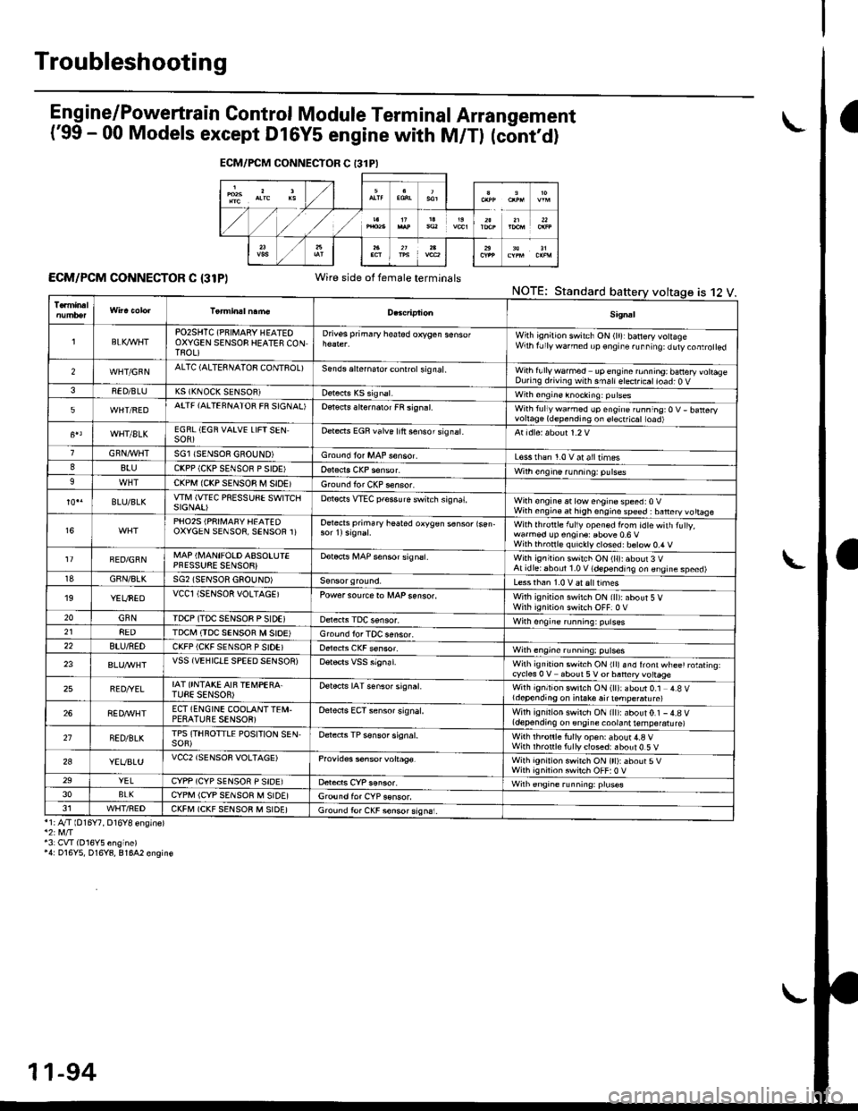
Troubleshooting
Eng ine/P_owertrain Control Module Term inal Arrangement
('99 - 00 Models except Dl6Y5 engine with M/Tl (cont,d)
ECM/PCM CONNECTOR C {31P)Wire side of female terminalsNOTE;Standard
*1;4"/T lD16Y7, D16Y8 ensinel
43: CVI(016Y5 engine)'4: D16Y5, D16Y8, 81642 engin€
ECM/FCM CONNECTOR C 13lPI
is 12 V.
Sig.al
lBLK4/VHTPO2SHTC (PNIMARY HEATEOOXYGEN SENSOB HEATES CONTROL)
Drivss primary hoated orygen sensofWith ignition switch ON (lr)rbanery volageWrh fJly warned up €ngir. ru..i19: duty.oaro ed
2WHT/GFNALTC (ALTESNATOB CONTSOL)Sends aliernalo. control sig nal,With fullywa.med upengine ronning; banery vohaseDuring d.iving with smallelect.icatioad; O V38ED/BLUK5 (KNOCK SENSOR)with sngine knocking: pulses
5WHT/REDATTF {AITEFNATOR FR SIGNAL'Detects slternaror FR si9n.l.With tullywarmed up engine running:O V- batteryvortage(dependingon erectficat toad)
WHT/8LKEGRL (EGN VAIVE LIFTSENSOR)Dete.ts EGR valve lrft sensorsignat.
GRN,4r'l/flTSGl ISENSOE GBOUND)Groond fo. MAP s€nsor.L€ss rhan 1.0 v at alltimes88luCKPP (CKP SENSOR P SIOE'With engine running: pulses9CKPM {CKP SENSOR M SIDEIGround for CKP sensor.
BLU/BLKwlvl (wEc PREssuSE swtTcllSIGNAI)D€tocts VTEC pfessure switch signat,With €ngine at low enginospeed:0VWith engin€ at high engino speed : banery vo ttaae
16PHO25 (PRII\,1AFY HEATEDOXYGEN SENSOR, SENSOR 1)Oetects primary heated oxygen s6nsor lsen-With lhrottle f!l1y open€d from idtewith tuly,wa.med !p engin€: Ebove 0.6 VWilh thronl€ quickly closed: b€tow 0.4 V
FED/GRNMAP (I\,4ANIFOLD ASSOLUIEPFESSUSE SENSOB}Dotocrs i,4AP sensor signsl.With ignitioh switch ON (ll):about 3 VAt idlei6boul 1.0 V (depending on engine speed)18GBN/8LKSG2 (SENSOR GSOUND)Less than 1.0 V aralttimes'19YEUNEDVCCl (SENSOR VOLTAGEIPowersourcero MAPsenso..With ignition swilch ON {ll):about 5 VWirh iqnition switch OFF]0 V20GNNIDCP (TDC SENSOB P SIDEIWith ongine running: pulses218EDTDCI\,I (TDC SENSOR M SIOE)Ground lor TOC aensor.22BTU/NEDCKFP (CKF SENSOR P SIDE)With engine running: p!lses
23VSS {VEHIClE SPEED SENSOR)Wilh ignrt|on swich ON rllr snd lront wl-ee' rotating.cycles 0 V about 5V or baneryvottage
25BED/YELIAT ONTAKE AIF TEi,4PEBA.TUEE SENSOR)Detects IAT senso. signat.With ignition switch ON (ll): about 0.1 4.8 Vldepending on i.take air ternpe.atu re)
268ED,ryVHTECT (ENGINE COOLANTTEI\,I.PESATUBE SENSOR)Oelects ECT sensor signal.With ignirion swirch ON {ll):about0.1 -4.8 V(depending on engine coolant temperatu re)
21NED/BLKTPS (THROTTLE POSITION SEN,SOF)Detects TP sensor signal.Wilh th.onle fully op€n: about 4.a VWith rhronle f!lly closed: about 0.5 V
2aYEVBLUVCC2 (SENSOR VOLTAGE)Provides s6nsor voltag€.With ignirion swirch ON (tt):about 5VWith ignilion swiich OFF:0 V29YELCYPP (CYP SENSOR P SIDE)Wilh €ngrne running: pruses3oBLKCYPM (CYP SENSOR M SIDE]G,ound for CYP sonsor.J1WHT/FEDCKFM (CKF SENSOB M SIDE)Ground fo. CKF sonsorsign6i.
11-94
Page 437 of 2189
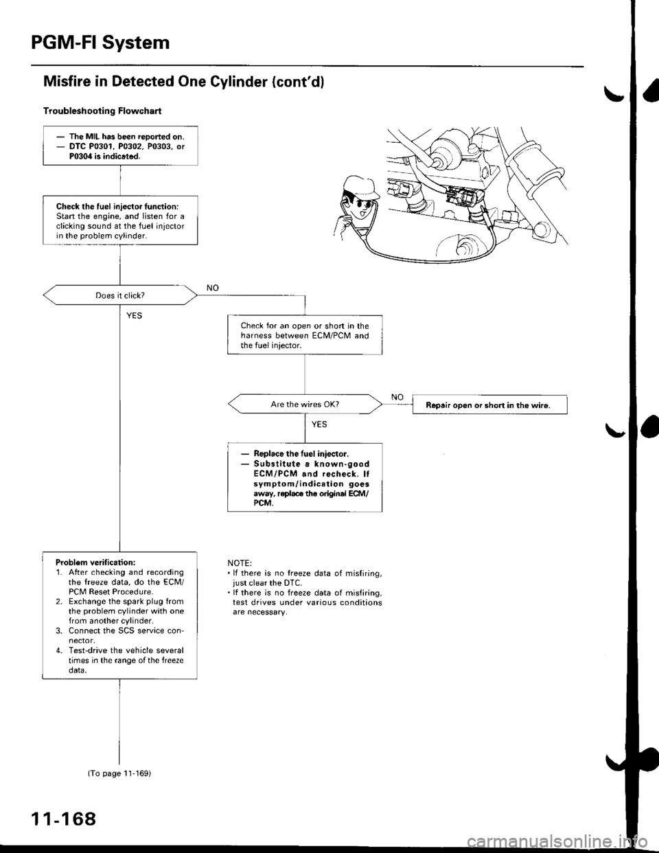
PGM-FI System
Misfire in Detected One Gylinder (cont'dl
Troubleshootin g Flowchart
NOTE:. lf there is no treeze data of misfiring,just clear the DTC.. It there is no freeze data of misfiring,test drives under various conditions
- The MIL has been reoorted on.- DTC P0301. P0302. P0303, orP030il is indicated.
Check the fuel iniecto. lunction:Stan the engine, and listen for aclicking sound at the fuel injectorin the problem cylinder.
Check for an open or short in theharness between ECM/PCM andthe fuel iniector.
Repair open or short in the wir€.
Replace the fuel iniector.Sub3titute a known-goodECM/PCM and recheck. Itsymptom/indication goesaway, replace the original ECM/PCM.
Problem verification:1. After checking and recordingthe freeze data, do the ECM/PCM Reset Procedure.2. Exchange the spark plug fromthe problem cylinder with onefrom another cylinder,3. Connect the SCS service con'nector,4. Test-drive the vehicle severaltimes in the range ofthe free2edata.
(To page 11-169)
1 1-1 68
Page 498 of 2189

t
Belore connecting a new fuel tube/quick-connect fining
assembly, remove the old retainer from the mating pipe
with thetabs pulled
apan, removeand discard the
I
retarner
New FUEL TUBE/OUICK.CONNECTFITTING ASSEMELY
3. Align the quick-connect fiftings with the pipe, and
align the retainer locking pawls with the connector
grooves. Then press the quick-connect fittings onto
the pipe until both retainer pawls lock with a click-
ing sound.
NOTE: lf it is hard to connect, put a small amount
of new engine oil on the pipe end.
Connection with new retainer:
4. Make sure the connection is secure and the pawls
are firmly locked into place; check visually and by
pulling the connector.
RCTAINER
Reconnect the battery negative cable, and turn the
ignition switch ON (ll). The fuel pump will run for
about two seconds, and fuel pressure will rise.
Repeat two or three times, and check that there is
no leakage in the fuel supplv system
11-229
Page 535 of 2189

Emission Control System
Positive Crankcase Ventilation IPCVI System
Descripiion
The Positive Crankcase Ventilation (PCV) system is
designed to prevent blow-by gas from escaping to the
atmosphere. The PCV valve contains a spring-loaded
plunger. When the engine starts, the plunger in the PCV
valve is lifted in proportion to intake manifold vacuum
and the blow-by gas is drawn directly into the intake
manifold.
D15Y5, D16Y8, 816A2 ongins:
BREATHERHOSE
Dl6'|11 6ngin6:
-: aLOW-BY VAPOR-: FnESH AIF
11-266
tJ
lrcpection
1. Check the PCV hoses and connections for leaks and
clogging.
2. At idle, make sure there is a clicking sound from the
PCV valve when the hose between the PCV valve
and the intake manifold is lightly pinched with your
fingers or pliers,
D16Y5, D16Y8 ongins:
BREATHERHOSE
PCV VALVE
Gently pinch here.
Bl6A2 engins:VALVE
lf there is no clicking sound, check the PCV valve
grommet for cracks and damage. If the grommet is
OK, replace the PCV valve and recheck.
PCV
Page 783 of 2189
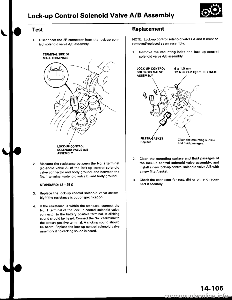
Lock-up Gontrol Solenoid Valve A/B Assembly
Test
'1, Disconnect the 2P connector from the
trol solenoid valve 1y'8 assembly.
TERMINAL SIOE OF
MALE TERMINALS
tocK-up con-
LOCK.UP CONTROLSOLENOID VALVE A/BASSEMBLY
Measure the resistance between the No. 2 terminal
(solenoid valve A) of the lock-up control solenoid
valve connector and body ground, and between the
No. 1 terminal (solenoid valve Bl and body ground.
STANDARD: 12 - 25 O
Replace the lock-up control solenoid valve assem-
bly if the resistance is out of specification.
lf the resistance is within the standard, connect the
No. 1 terminal of the lock-up control solenoid valve
connector to the battery positive terminal. A clicking
sound should be heard. Connsct the No. 2 terminal to
the battery positive terminal. A clicking sound should
be heard. Replace the lock-up control solenoid valve
assembly if no clicking sound is heard.
Replacement
NOTE: Lock-up control solenoid valves A and I must bs
removed/replaced as an assembly.
1. Remove the mounting bolts and lock-up control
solenoid valve Ay'B assemblv.
6 r 1.0 mm12 N.m (1.2 kgf.m,8.7 lbl.ftl
/:'-
Clean the mounting surfaceand fluid psssages.
Clean the mounting surface and fluid passages of
th6 lock-up control solenoid valve assembly, and
instsll a new lock-up control sol€noid valve Ay'B with
a new filtsr/gask€t.
Check the connector for rust, dirt or oil, and racon-
nect it securely.
1+105
Page 784 of 2189
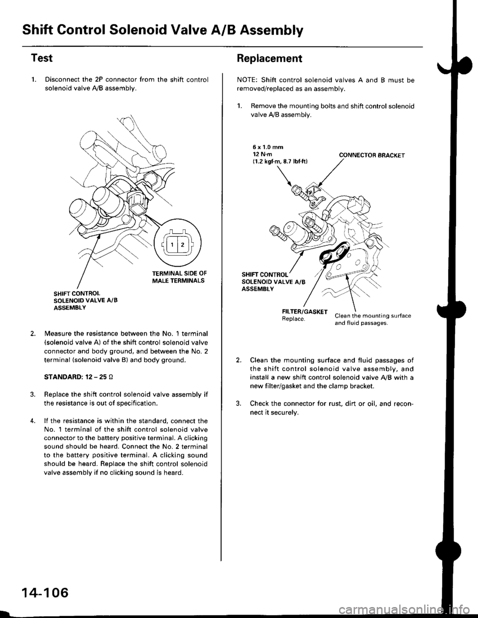
Shift Control Solenoid Valve A/B Assembly
Test
1. Disconnect the 2P connector from the shift control
solenoid valve A,/B assemblv.
SHIFT CONTROLSOLENOID VALVE A/B
ASSEMBLY
N4easure the resistance between the No. 1 terminal(solenoid valve A) of the shift control solenoid valve
connector and body ground, and between the No. 2
terminal (solenoid valve B) and body ground.
STANDARD: 12 - 25 O
Replace the shift control solenoid valve assembly if
the resistance is out of specification,
lf the resistance is within the standard, connect the
No. 1 te.minal of the shift control solenoid valve
connector to the battery positive terminal. A clicking
sound should be heard. Connect the No. 2 terminal
to the battery positive terminal. A clicking sound
should be heard. Replace the shift control solenoid
valve assembly if no clicking sound is heard.
14-106
Replacement
NOTE: Shift control solenoid valves A and B must be
removed/replaced as an assembly.
1. Remove the mounting bolts and shift control solenoid
valve A,/B assembly.
5xL0mm12 N.m(1.2 kgf.m,8.7 lbf.ft)CONNECTOR BRACKET
FILTER/GASKETBeplace.Clean the mounting surfaceand fluid passages.
Clean the mounting surface and fluid passages of
the shift control solenoid valve assembly, and
install a new shift control solenoid valve Ay'B with a
new filter/gasket and the clamp bracket.
Check the connector for rust. dirt or oil. and recon-
nect it securelv,
Page 785 of 2189

Linear Solenoid Assembly
Test
1. Disconnect the linear solenoid connector.
LINEAR SOLENOID
4.
Measure the resistance between the No. 1 and the
No. 2 terminals of the linear solenoid connector.
STANDARD: applox. 5 O
lf the resistance is out of specification, replace the
linear solenoid assembly.
Connect the No. 2 terminal of the linsar solenoid con-
nector to the batterv positive terminal and connect
the No. 1 terminal to the battery negative terminal A
clicking sound should be heard.
lf not, remove the linear solenoid assembly.
Check that the linear solenoid fluid passage Ior dust
or dirt.
Connect the No. 2 terminal of the linear solenoid
connector to the battery positive terminal and con-
nect the No, 1 terminal to the battery negative terma-
nal. Check that the valve moves.
Disconnect one of the battery terminals and check
that the valve releases.
NOTE: You can see the valve movement through
the fluid passage in the mounting surface of the lin-
ear solenoid assembly.
LINEAR SOLENOID
VALVE
lf the valve binds, or moves sluggishly, or the linear
solenoid does not operate, replace the linear solenoid
assembly.
1.
14-107