Page 968 of 2189

Linear Solenoids/lnhibitor Solenoid
)Test
1. Disconnect the 8P connector from the solenoid har-
ness connector.
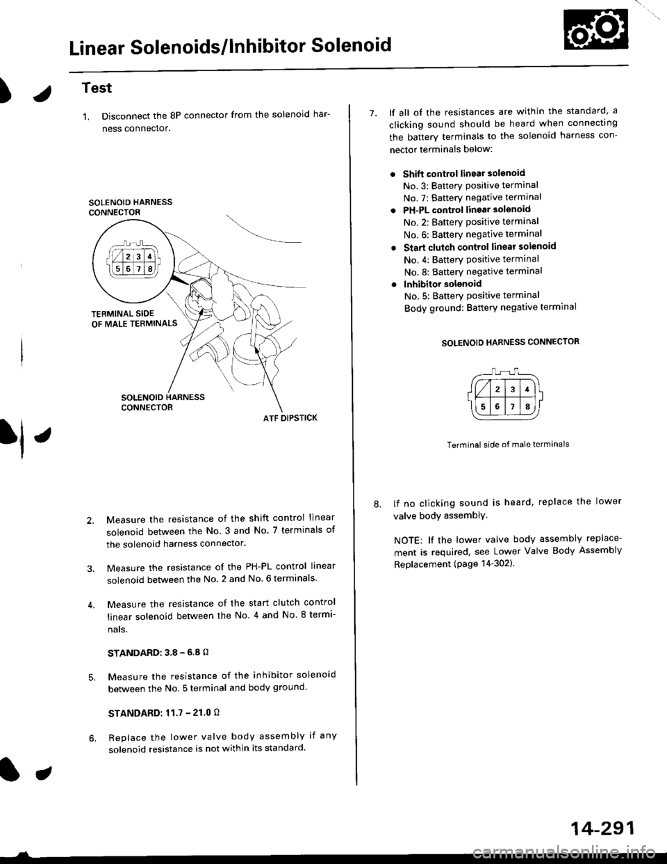
SOLENOID HARNESSCONNECTOR
ATF OIPSTICK
Measure the resistance of the shift control linear
solenoid between the No. 3 and No. 7 terminals of
the solenoid harness connector.
Measure the resistance of the PH-PL control linear
solenoid between the No. 2 and No. 6 terminals
Measure the resistance of the start clutch control
linear solenoid between the No 4 and No. 8 termi-
nats,
STANDARD:38-6.8O
Measure the resistance of the inhibitor solenoid
between the No. 5 terminal and body ground
STANDARD:11.7 - 21.0 O
Replace the lower valve body assembly if any
solenoid resistance is not within its standard.
7. lf all ot the resistances are within the standard, a
clicking sound should be heard when connectrng
the batterv terminals to the solenoid harness con-
nector terminals below:
Shift control linear solsnoid
No.3: Batterv Positive terminal
No. 7: Battery negative terminal
PH-PL control linear solenoid
No.2: Batterv oositive terminal
No. 6: Baftery negative terminal
Start clutch control linear solenoid
No. 4: Battery Positive terminal
No.8: Battery negative terminal
lnhibitor solsnoid
No,5: Batterv Positive terminal
Body ground: Battery negative termrnal
SOLENOID HARNESS CONNECTOR
Terminal side of male terminals
lf no clicking sound is heard, replace the lower
valve body assemblY,
NOTE: lf the lower valve body assembly replace-
ment is required, see Lower Valve Body Assembly
Replacement (page 14-302).
14-291
Page 1082 of 2189

Troubleshooting
Noise and Vibration
NOTE; Pump noise in first 2 - 3 minutes after starting in cold weather is normal.
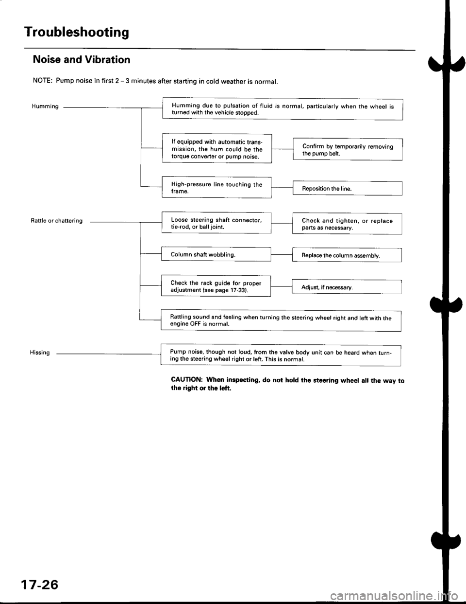
Humming
Rattle or chattering
Humming due to pulsation of fluid is normal, particularlv when the wheel isturned with the vehicle stooDed.
lf equipped with automatic trans-mission, the hum could be thetorque conveater or pump noise.
Confirm by temporarily removingthe pump belt.
High-pressure line touching theframe.Reposition the line.
Loose steering shaft connector,tie-rod. or balljoint.Check and tighten, or replacepaats as necessary.
Column shaft wobbling.Replace the column assembly.
Check the rack guide tor properadjustment (see page 17,33).Adiusi, if necess€ry.
Rattling sound and feeling when turning the steering wheel raght and left with theengine OFF is normal.
Pump noise, though not loud. trom the valve body unit can be heard whon turn-ing the steering wheel right or left. This is normat.
CAUTION: When imp€sting, do not hold the steering wheet a[ the way tothe right or the left.
17-26
Page 1208 of 2189

tJ
t\
Kickback
1. The motor operates when the ABS is functioning, and the fluid in the reservoir is forced out to the master cylinder
causing kickback at the brake pedal.
2. TheABScontrol unit operates the solenoid valve when the brake pedal is released afterthe initial diagnosis Youmay
hear the faint solenoid valve operation sound at this time. but it is normal.
Pump Motor
1. The pump motor operates when the ABS is functioning
2. The ABS control unit checks the pump motor operation during acceleration. You may hear the faint operation sound
at this time. but it is normal.
Brake Fluid Replacament/Air Blsading
1. Brake fluid replacement and air bleeding procedures are the same as for conventional brakes
Troubleshooting
1. The troubleshooting flowcharts explain the procedures on the assumption that the cause of the problem is still pre-
sent and the ABS indicator light is still on.
Note that troubleshooting following the flowchart when the ABS indicator light does not come on can result in incor-
rect judgment.
2. Ouestion the customer about the conditions when the problem occurred, and try to reproduce the same conditions
for troubleshooting.
self,diagnosis is made at various times such as the initial diagnosis, except ABS control. during ABS control, during
acceleraiion, during the specified vehicle speed, etc. Therefore, the symptom cannot be checked unless the check
conditions match with the problem conditions
3. When the ABS indicator light does not come on during the test drive, but the troubleshooting is performed based on
the DTC, check for the loose connectors. poor contact of the terminals, etc, before troubleshooting.
4. After troubleshooting, erase the DTC and test-drive the car. Be sure that the ABS indicator light does not come on.
5. The connector illustrations show the female connectors with a single outline and the male connectors with a double
ouflrne.
6. The connector terminal cavities containing female terminals are always numbered by looking at the connector from
the wire side. and the cavities containing male terminals are always numbered by looking at the connector from the
terminal side.
r'
19-55
Page 1471 of 2189

l'f .
Electrical
Special Toofs .,....................,23-2
Troubleshooting
Tips and Precautions ..............,.................... . 23-3
Five-step Troubleshooting .............. ......... . . 23-5
wire color codes ..........,23-5
Schematic Symbols ........,................... . . .. .... 23-6
Relay and Control Unit Locations
Engine Compartment ...,..................... ... .. . 23'7
Dashboard ......................23-8
Dashboard/Door ......... 23-12*Airbags ................. ....... Section 24
Air Conditioning ......... Section 21
Aftelnator ..........."""" """ 23-112
Anti-lock Brake System {ABS) Section 19*A/T Gear Position Indicator .....................,. .... ... 23-149
Automatic Transmission Svstem .... . ....... Section 14
Batterv ......... . . . ... ...... .......23-91
Blower controls .. . ... Section 2l
Charging System ....'...........23'112
Connector ldentilication and Wire Harness
Routing .................. ......23'13
Cruise Control ............,........23-240
Dash Lights Brightness Controller ............. ....... 23-180
Fan controfs "" 23'126
Fuel PumD ........ . ........ section 11
Fuses/Refay ...............,..,,.. 23'62
PGM-FI Control System ......................,....... Section 1 1
*Gauges
Circuit Diagram ....,.,.......23-131
Fuef Gauge ...........'.'.......23-142
Gauge/lndicator .. . .. 23-129
Ground Distribution .. . 23-75
Heatei controls .. . ..... Section 21*Horn................. ...............23-196
*tgnition Switch ....................23-89
lgnition System .......,.... 23-102
*lntegrated Control Unit ....................................... 23-156
fnterlock System ,........ . . , ,23-144
Lighting System . . . .. ......... 23-161
Lights, Exterior
Back-up Lights ..'............23'171
Brake Lights .................. 23'174
Daytime Bunning Lights (Canadal ............... 23'166
Front Parking Lights ......,................ .'. .......... 23-167
Front Turn Signal Lights .......... . . ............ ..,.23-167
Headtights ....".'....-... ..... 23'167
High Mount Brake Light ...................... ... .23'179
License Plate Lights ...... 23'176
Taitfights ................ .......23'171
lnterior Lights ..-.......,, . 23-142
Moonroof ..,.................,........ 23-235
Power Distribution ....... . . .23-61
Power Door Locks .......,,,. .23'251
Power Mirrors ,..............,.,...23'206
Power Relays ....... . ...... . . .. 23-86
Power Windows ............,,....23-220
Rear Window Defogger .......................... . . ... . . 23-2OO
Spark Plugs . ..... . ........ .....23-111
Slarting System ................23-93*stereo Sound Svstem ,................. ..... ... . ... ,.,.,,23'147'Supplemental Restraint System (SRS) ... . Section 24
Turn Signal/Hazard Flasher System .......'.'....-... 23-173
*Undel-dash Fuse/Relay Box ............,.................. 23-85
vehicfe soeed sensor (VSSI """" ""' 23-140+Wipers/Washers .........,.,.,...23-214
NOTE: Unless otherwise specified, references to auto-
matic transmission (Mf) in this section include the CVT.
Page 1657 of 2189
Stereo Sound System
Component Location Index
SRS components are located in this area. Review the SRS component locations, precautions. and procedures in the SRS
section (24) before performing repairs or service.
'96 - 98 models
AUDIO UNIT(STEFEO RADIO TUNERIBeplacement, page 23 189Terminals, page 23-190
ANTENNA MASTReplacement, page 23 193
RIGHT TWEETERReplacement, Page 23 191
LEFT TWEETERReplacement, Page 23 191
ANTENNA LEAD
LEFT FRONT SPEAKER
Replacement, Page 23'191
SUB
RIGHT FRONT SPEAKERReplacement, page 23'191
ANTENNALEAD
CASSETTE PLAYER
Replacement, Page 23-189REAR SPEAKERSReplacement, page 23- 19'l
(cont'd)
23-147
q-
Page 1658 of 2189
Stereo Sound System
Component Location Index {cont'd)
SRS components are located ln this area. Review the SRS component locations, precautions, and orocedures in the sRSsection (24) before perlorming repairs or service.
'99 - 00 models
AUDIO UNITFeplacement, page 23-189Terminals, page 23-190
ANTENNA MAST (Coupe/Hatchbeck)Replacement, page 23,193RIGHT TWEETERReplacement, p6ge 23-191
LEFT TWEETERReplacement, page 23-191
ANTENNA LEAD
LEFT FRONTReplacement, page 23-191
RIGHT FRONT SPEAKERReplacernent, page 23-191
WINDOW ANTENNA {SedanlWire Test, page 23 192Wire Repair, page 23-192
SUB
I.TAO
REAR SPEAKERSReplacemont, page 23-191
23-1AA
Page 1660 of 2189
Stereo Sound System
UNDER-DASI.]FUSEi RELAY 8OX
l- '-r,*;l
I
I
I
I
I
I
IYEUFED
(Sedan)--l
(Coupe/Horchbach)
Circuit Diagram ('99 - 00 models)
No 30 (7.54)FUSE
V
IRED/BLK
I
I
I
vDASH LGHTSBHIGHTNESSCONTROLLER
F;*";
,,,[.J:,a*[rrl
BLK
G501
/ _- | neolcn;diFnoNi | |DooR SPEAKEF | |
HlGHTTWEETER
UNDER.HOOD FUSE/RELAY BOX
RIGHT REAFSPEAKEBLEFT REARSPEAKEF
LEFTTWEETER
23-190
Page 1662 of 2189

Stereo Sound System
Stereo Radio Tuner Terminals
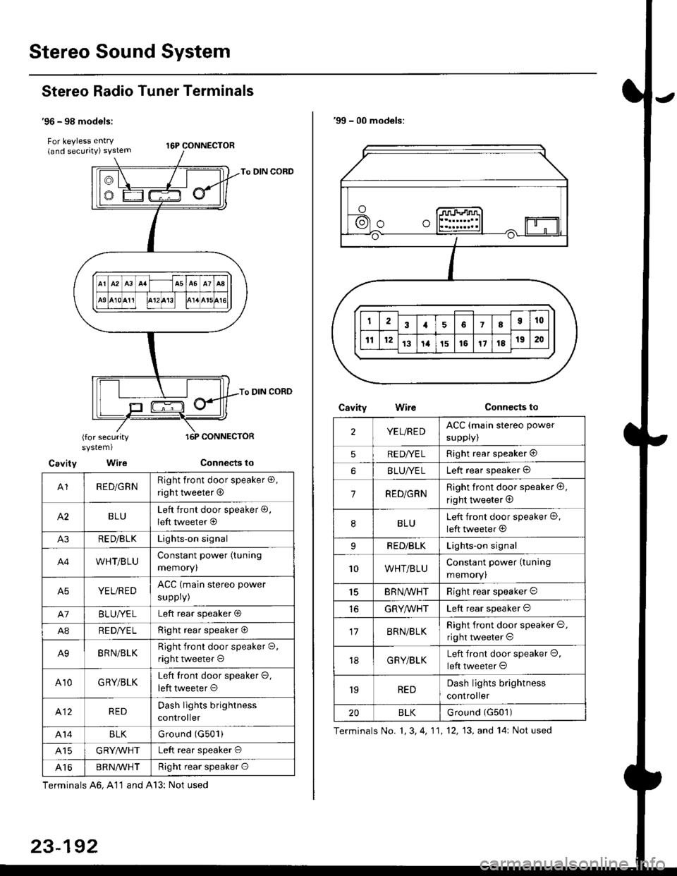
'96 - 98 models:
For keyless entry . t6p coNNEcroR(and securrty) syslem
To DIN CORD
To DIN CORD
(for securitysystem)
Cavity Wire
A1RED/GRNRight front door speaker o,
right tweeter @
BLULeft front door speaker @,
left tweeter @
A3RE D/B LKLights-on signal
A4WHT/BLUConstant power (tuning
memoryl
A5YEL/REDACC (main stereo power
suppry)
A7BLUI/ELLeft rear speaker O
A8RE DI/E LRight rear speaker O
A9BRN/BLKRight front door speaker O,
right tweeter o
A10GRY/BLKLeft tront door speaker O,
left tweeter O
412REDDash lights brightness
controller
A14BLKGround (G501)
415GRYMHTLeft rear speaker O
Al6BR N/VVHTRight rear speaker O
Terminals A6, A11 and A13: Not used
23-192
'99 - 00 models:
CsvityConnccts toWire
2YEL/REDACC (main stereo power
suppry)
5RE DI/E LRight rear speaker @
BLUI/ELLeft rear speaker @
7RED/GRNRight front door speaker @,
right tweeter @
8BLULeft front door speaker @,
left tweeter @
9RED/BLKLights-on signal
10WHT/BLUConstant power (tuning
memory)
15BRN,ryVHTRight rear speaker O
GRYMHTLeft rear speaker O
17BRN/BLKRight front door speaker O,
right tweeter O
18G RY/BLKLeft front door speaker O,
left tweeter O
'19REDDash lights brightness
controller
20BLKurouno t(l5u t,
Terminals No. 1, 3, 4, 11,12, 13, and 14: Not used