1998 HONDA CIVIC Cat transmission
[x] Cancel search: Cat transmissionPage 898 of 2189

Description
Hydraulic Flow (cont'd)
lll position, when th€ electronic control system is fauhy.
when the electronic control svstem (linear solenoids and sensors) is faulty, the transmission uses the pitot pipe pressure(PP) to 311o- rh" u"hicle to drive.
when all linear solenoids and sensors are off because of a faulty electronrc control system, clutch reducing pressure (cR)flows to the start clutch control valve, the manual valve, the PH-PL control valve, and the shift control valve. clutch reduc-ing pressure (cR) becomes shift varve pressure (sV) at the shift contror varve, and shift varve pressure {sv) is appried tothe left end of the shift valve and the right end of the shift inhibitor valve. The shift valve moves to the right side. anduncovers the pon that leads high pressure (PH) to the drive pulley and uncovers the po.t tlr"t r""1" ro,,"-pressure (pL) tothe driven pulley At this time, the pulley ratio is high, The shift inhibitor valve moves to the left side, and uncovers theport that leads shift inhibitor pressure (Sll to the pitot lubrication pipe and the pitot regulator valve. tne prtot lubricationpipe discharges fluid inside of the pitot flange, and discharged fluid enters into the pitot pipe and it is applied to the leftend of the pitot regulator valve. The pitot regulator valve moves lo the right side, and uncovers the port that leads pitotregulator pressure (PR) to the shift inhibitor valve. Pitot regulator pressure {pR) becomes start clutch pressure {sc1 at theshift inhibitor valve, and is applied to the stan clutch. The stan clutch rs engaged. The forward clutch pressure (FWD) isapplied to the forward crutch, and the forward crutch is engaged. This alows the vehicre to drive.
NOTE: When used. "|eft" or ,,right', indicates direction on the hydraulic circuit.
14-220
I.
Page 906 of 2189

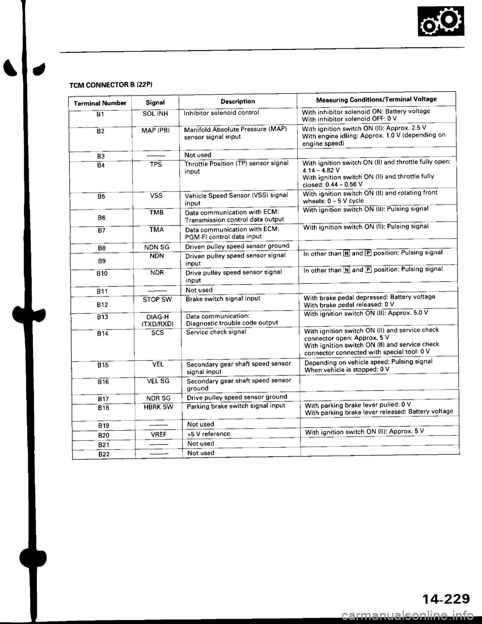
TCM CONNECTOR B (22P}
Terminal NumbelSignalDescriptionMeasuring Conditions/Terminal Voltage
B1SOL INHInhibitor solenoid controlWith inhibitor solenoid ON: Baftery voltage
With inhibitor solenoid OFF: 0 V
82MAP (PB)-M an if old Absol r-rte Pressure IMAP)
sensor signal inPUtWith iqnition switch ON (ll): Approx.2.5 V
With e;gine adling: Approx. 1.0 V (depending on
engine speed)
B3Not used
B4TPS-Throttle Position (TP) sensor signal
input
With ignition switch ON (ll) and throftle fully open:
4.14 - 4.42 VWith ignition switch ON (ll) and throttle fully
closed: 0.44 - 0.56 V
VSSVehicle Speed Sensor (VSS) signal
Inpur
With ignition switch ON (ll) and rotating front
wheelsr 0-5Vcycle
TMBData communication with ECM:
Transmission control data outpUt
With ignilion swltch UN lll): rulslng slgnar
81TMAData communication with EClvl:
PGM Fl control data inPut
With ignition swltch uN {ll,: l-ulslng slgnal
B8NDN SGDriven pulley speed sensor ground
B9NDNDriven pulley speed sensor signal
input
ln other thTnE and E position: Pulsing signal
810NDRDrive pulley speed sensor signal
Input
-tn ottrer ttran E ana E position: Pulsing signal
811Not used
812STOP SWBrake switch signal inPutWith brake pedal depressed: Battery voltage
With brake pedal released: 0 V
813DIAG-H(TXD/RXD)Data communication:Diagnostic trouble code outPut
Wittr ignitio.r s*itct' ON (ll): Approx 5.0 V
814Se-ice ctrect signatWith ignition switch ON (ll) and service check
connector oPen: APProx.5 V
With iqnition switch ON (ll) and service check
"onn"itot. connect"d with special tool: 0 V
Secondary gear shaft speed sensor
signal input
Depending on vehicle speed: Pulsing signal
When vehicle is stoPped: 0 V815VEL
816VEL SGSecondary gear shaft speed sensorgrouno
817NDR SGDrive pulley speed sensor ground
818HBRK SWParking brake switch signal inPutWith parking brake lever pulledr 0 V
With parking brake lever released: Battery voltage
819Not used
B�20VREF+5 V relerenceWith ignition switch ON (ll): Approx 5 V
821Not used
Not used
Page 920 of 2189

Troubleshooting Flowchart - Vehicle Speed Sensor (VSS)
NOTE: Record all freeze data before you troubleshoot'
Po$rible Ctuse
. Disconnected vehicle speed
sensor (VSS) connectol. Short or open in VSS wire' Faulty VSS
@. Make sure lifts, iacks, and sal€tY stands are placed properly lsoe section 1)'
. Set the parking brake securelv, and block the rear wheels'
. iacr upile rront or the vehicle, and support it with safety st'nds'
TCM CONNECTORS
Wire side of female terminals
. OBD ll Scan Tool indicates Code
P1791.. Setf-diagno3is E indicato. light
blinks tour times.
Refer to seclion 23 for vehicle
soeed sensor IVSSI test
Check the VSS Voltage:
1. Raise the vehicle2. Shift the transmission to lEposrtlon.3. Disconnect the A (26P) and B(22P) connectors from the
TCM.4. Turn the ignition switch ON {ll).
5. Rotate the front wheel and
check for the voltage between
the 85 and 413 or A26 termi-
nals. Block the other wheel so
at does not turn
Check for oP€n in the wire
between the 85 terminal and the
vehicle speed sensor {VSS}. lf
wire is OK, check the vSS (see
soction 23).
Does0Vandapprox 5 V or more
appear alternatelY?
Check for loos€ TCM connedors
lI nec€ssary, substitute a known'
good TCM and recheck.
14-243
Page 970 of 2189

Start Clutch Control@
T
Start Clutch Calibration Procedure
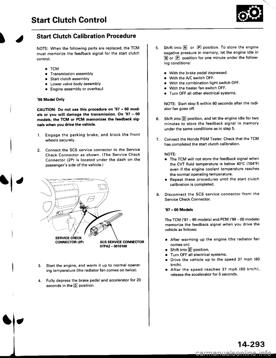
NOTE: When the following parts are replaced, the TCM
must memorize the feedback signal for the start clutch
control.
. TCM
. Transmissionassembly
. Stan clutch assembly
. Lower valve bodv assembly
. Engine assembly or overhaul
'96 Model Only
CAUTION: Do not uso this procsdure on'97 - (X) mod-
els or you will damage the transmission. On '97 - 00
models, the TCM or PCM memorizes ths loodback sig'
nals when you drive the vehicle.
1. Engage the parking brake, and block the front
wheels securely.
2. Connect the SCS service connector to the Service
Check Connector as shown. (The Service Check
connector (2P) is located under the dash on the
passenger's side of the vehicle.)
CONNECTOR07PAZ - lDl01(xt
Start the engine, and warm it up to normal operat-
ing temperature (the radiator fan comes on twice).
Fully depress the brake pedal and accelerator for 20
seconds in the E] position.
rl ,
CONNECTOR I2PI
14-293
7.
Shift into E o|. E position. To store the engine
negative pressure in memory. Iet the engine idle in
E or E position for one minute under the follow-
ing conditions:
. With the brake pedal depressed,
. with the y'\/c switch oFF.
. With the combination light switch OFF.
. With the heater fan switch OFF.
. Turn OFF all other electrical systems
NOTE: Start step 5 within 60 seconds after the radi-
ator fan goes off.
Shift into E position, and let the engine idle for two
minutes to store the feedback signal in memory
under the same conditions as in step 5.
Connect the Honda PGM Tester. Check that the TCM
has completed the start clutch calibration.
NOTE:
. The TCM will not store the feedback signal when
the CVT fluid temperature is below 40"C (104'F)
even if the engine coolant temperature reaches
the normal operating temperature.
. Repeat these procedures until the start clutch
calibration is completed-
Disconnect the SCS service connector from the
Service Check Connector.
'97 - 00 Models
The TCM ('97 - 98 models) and PCM ('99 - 00 models)
memorize the feedback signal when you drive the
vehicle as follows:
. After warming up the engine (the radiator fan
comes onl.
. Shift into E position.
. Turn OFF all electrical systems,
. Drive the vehicle up to the speed 37 mph (60
km/h).
. After the speed reaches 37 mph (60 km/h),
release the accelerator for 5 seconds.
Page 975 of 2189

Stall Speed
Test
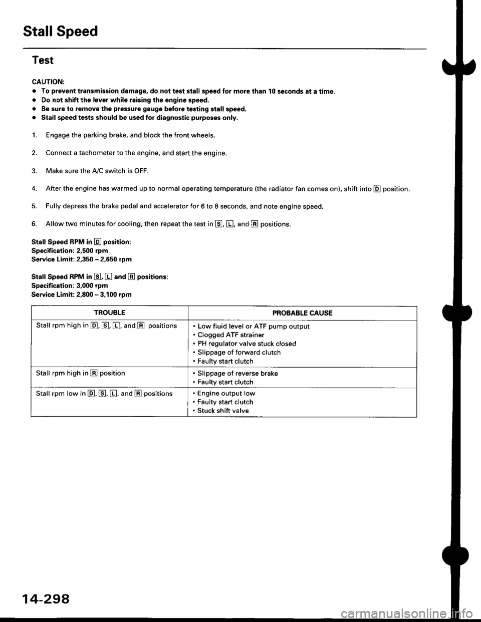
CAUTION:
. To prevent transmission damage, do not test stall sp€€d for mole than 10 seconds at a time.
. Do not shift the lsver whils raising the engine speod.
. Be sure lo remove the pressure gauge before tosting stall speed.
. Stall speed tssts should be used tor diagnostic purposes only,
1. Engage the parking brake, and block the tront wheels.
2. Connect a tachometer to the engine, and stan the engine.
3. Make sure the A/C switch is OFF.
4. After the engine has warmed up to normal operating temperature (the radiator fan comes on), shift into E position.
5. Fully depress the brake pedal and accelerator for 6 to 8 seconds, and note engine speed,
6. Allow two minutes for cooling, then repeat the test in E, E, and E positions.
Stall Speed BPM in E poshion:
Specification: 2,500 rpm
Servic€ Limit: 2,350 - 2.650 rpm
Stall Speed RPM in E, E and E positions:
Specitication: 3,000 rpm
Service Limit: 2,800 - 3,100 rpm
TROUBLEPROBABLE CAUSE
Stall rpm high in @. p. [, and @ positionsLow fluid level or ATF pump output
Clogged ATF strain€r
PH regulator valve stuck closed
Slippage of forward clutch
Faulty start clutch
Stall rpm high in E position. Slippage of reverse brake. Faulty start clutch
Stall rpm low in E, P, [, and @ positionsEngine output low
Faulty stan clutch
Stuck shift valve
14-294
Page 978 of 2189

1.
Start the engine.
Shift to the respective shift lever positions in the table, and measure the following pressures at 1'500 rpm'
. Forward Clutch Pressure
. Reverse Brake Pressure
. Drive Pulley Pressure
. Driven Pulley Pressure
8. Shift to E posltion, and measure the lubrication pressure at 3,000 rpm'
Disconnect the special tool after pressure testlng
Install the sealing boits in the jnspection holes with new sealing washers, and tighten the bolts to the specified
toroue.
TOROUE: 18 N.m {1.8 kgf'm, 13 lbf'ft}
CAUTION: Keep all foreign particles out of the transmission'
9.
10.
PBESSURESHIFT LEVER
POSmONSYMP{OMPROBABLE CAUSE
FLUID PRESSURE
Standard/Ssrvice Limit
Forwa rd
Clutch
ENo or low for-
ward clutch
pressure
Forward Clutch1.4 - 1.75 MPa
(14.3 - 17.8 kgtcm'�, 203 - 253 Psi)
Reverse
Brake
tsNo or low
reverse brake
pressure
Reverse Brake1.4 - 1.75 MPa
(14.3 - '17.8 kg7cm'�, 203 - 253 Psi)
Drive
Pulley
NNo or low
drive pulley
pressure
ATF pump, PH reg-
ulator valve, PL
regulator valve,
Shift valve
0.2 - 0.7 MPa
(2 - 7.1 kgflcm'�, 28 - 101 Psi)
Drive pulley
pressure roo
high
PH regulator valve,
PL regulator valve,
Shift valve. Shift
control linear
solenoid
Driven
Pulley
No or low
driven pulley
pressure
ATF pump, PH reg-
ulator valve, Shift
valve, Shift control
linear solenoid
1.5 - 2.3 MPa
(15.3 - 23.5 kg?cm'�, 218 - 334 Psi)
Driven pulley
pressure too
h igh
PH regulator valve
LubricationNo or low
lubrication
pressure
ATF pump,
Lubrication valve
Above 0.2 MPa
(Above 2 kgf/cm'�. 30 Psi)
14-301
Page 990 of 2189

6) TRANSMISSION HOUSING GASKET Replace'
@ DOWEL PIN
@) ATF FEED PIPE
@ o-RING Replace.
60 o-RING Replace.
@) DRIVE PULLEY SPEED SENSOR
@ TRANSMISSION HANGER
@ SNAP RING
@ txaust Sxtfu, zs t 31 mm selective part
@ SALL BEARING
6J RING GEAR6D SNAP RING
@ aevense aRlxe rND PLATE Selective part
@ REVERSE BRAKE DISC
@ REVERSE BRAKE PLATE
@ DISC SPRING6} THNUST WASHER
@} finusr NeeoLr eelnNc
@ THRUST WASHER
@ GARRIER ASSEMBLY
@ THRUST WASHER
@ THRUST NEEDLE BEARING
@} SUN GEAR
@ SEALING RING REPIACE'
@ NEEDLE BEARING
@ INPUT SHAFT
@ NEEDLE BEARING
@ SEALING RING FEPIACE'
@ SEALING RING {RUBBERI Replace'
@ ATF FEED PIPE
O END COVER
O ATF FEED PIPE
O DOWEL PIN
@ O-RING Replace.G) FEED PIPE FLANGE
@ reeo ppe ruruce puru
O] ROLLERO IruTENMEDNTE XOUSING ASSEMBLY
ao corutnoL sxlrr lsseugLv
@ tnlrusmtsstottt ttoustt'tc
@ SHIFT CABLE BRACKET
c) BREATHER CAP
@ oll- SEAL Replace.
@ CONTROL LEVER
G LoCK WASHER Replace.(D secololaY ceaR SHAFT SPEED sENsoR
o) onvel put-uv sPEED SENSOR
@ O-RING Replace.(O SNAP RING6 rnmrsutsstoru xouslNc oRlvEN PULLEY
SHAFT ROLLER BEARING
@ END COVER GASKET REPIACE'
@ o-RING Replace
6o mnruulL vnLVe goDY LINE A
64 MANUAL VALVE BODY LINE B
@ O-RING Replace.
@ DETENT SPRING
O ATF FEED PIPE
@ O-RING Replace.
@ MANUAL VALVE EODY
@ DOWEL PIN
@ r'rllull valve goDY SEPARAToR PLATE
6D SNAP RING
@t roRwlno cturcx ASSEMBLY
@ o-RING Replace
@ SNAP RINGo3 spnlruc aetlrupn/RETURN SPRING ASSEMBLY
@ nevense ennr eBtottt
@ o-RING Feplace.
@ SNAP RING RE'AINER
@ ATF FEED PIPE
.1,
TOROUE SPECIFICATIONS
6x1.0mm
6x1.0mm
8 x 1.25 mm
8 x 1.25 mm
8 x 1.25 mm
12 N.m (1.2 kgf'm,8.7 lbf'ft)
14 N.m {1.4 kgf'm, 10 lbift)
37 N.m (3.8 kgf'm, 27 lbf'ft)
26 N.m (2.7 kgf'm,20 lbf'ft)
29 N.m (3.0 kgf'm, 22 lbf'ft)
6B
8B
8F
8G
14-313
rl,
Page 1015 of 2189

1.
7.
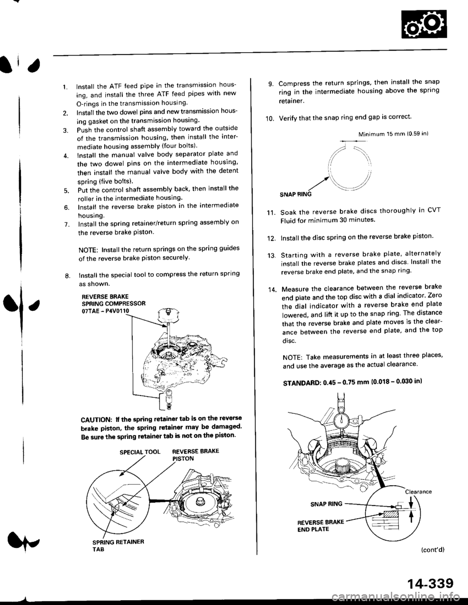
lnstall the ATF feed pipe in the transmission hous-
ing, and install the three ATF feed pipes with new
O-rings in the transmission housing,
Install the two dowel pins and new transmission hous-
ing gasket on the transmission housing.
Push the control shaft assembly toward the outside
of the transmission housing, then install the inter-
mediate housing assembly (four bolts).
lnstall the manual valve body separator plate and
the two dowel pins on the intermediate housing,
then install the rnanual valve body with the detent
spring (five bolts).
Put the control shaft assembly back, then install the
roller in the intermediate housing.
lnstall the reverse brake piston in the intermediate
housing.
Install the spring retainer/return spring assembly on
the reverse brake Piston.
NOTE: Installthe return springs on the spring guides
of the reverse brake piston securely
tnstall the special tool to compress the return spring
as shown.
REVERSE BRAKESPRING COMPRESSOR07TAE - P4V0110
6.
L
1
CAUTION: lf the spring retainer tab is on the reverse
brakc piston, the spring rstainer may be damaged'
Be sure the spring retainer tab is not on the piston'
rp
SPECIALTOOL REVERSEBRAKE
-^
14-339
10.
9.
14.
Compress the return springs, then install the snap
ring in the intermediate housing above the spring
retainer.
Verify that the snap ring end gap is correct'
Mini
/,,- '-t,,,,.
// \i/ ',r
'1 ,
.r' //'/. .-J?RINGSNAP
mum 15 mm 10.59 in)
Soak the reverse brake discs thoroughly in CVT
Fluid for minimum 30 minutes.
Installthe disc spring on the reverse brake piston'
Starting with a reverse brake plate, alternately
install the reverse brake plates and discs lnstall the
reverse brake end plate, and the snap ring'
Measure the clearance between the reverse brake
end plate and the top disc with a dial indicator' Zero
the dial indicator with a reverse brake end plate
lowered, and lift it up to the snap ring The distance
that the reverse brake and plate moves is the clear-
ance between the reverse end plate, and the top
disc.
NOTE: Take measurements in at least three places'
and use the average as the actual clearance'
STANDARD: 0.45 - 0.75 mm (0.018 - 0'030 in)
{cont'd)
11.
12.
13.