1998 HONDA CIVIC Cat transmission
[x] Cancel search: Cat transmissionPage 1504 of 2189
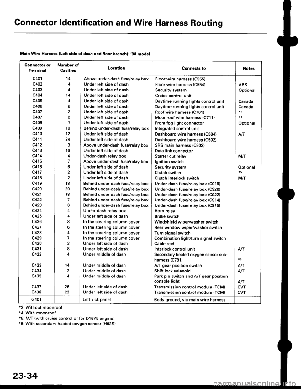
Connector ldentification and Wire Harness Routing
Connoctor or
Tgrminal
Number of
CavitiesLocationConneqts toNot€s
c401
c402
c403
c404
c405
c406
c407
c407
c408
c409
c410
c411
c4't2
c413
c414
c415
c416
c417
c418
c419
c420
c421
c422
c423
c424
c425
c426
c427
c428
c429
c430
c431
c432
c433
c434
c435
c437
c438
't4
l4
8,
1
10
12
24
7
6
18
20
18
7
6
8
7
8
14
2
Above under-dash fuse/relay box
Under left side of dash
Under left side of dash
Under left side of dash
Under left side of dash
Under left side of dash
Under left side of dash
Under left side of dash
Under left side of dash
Behind under-dash fuss/relay box
Under left side of dash
Under left side of dash
Above under-dash fuse/relay box
Under left side of dash
Under-dash relay box
Above under-dash fuse/relay box
Under left side of dash
Under left side of dash
Under left side of dash
Eehind under-dash fuse/relay box
Behind under-dash fuse/relay box
Behind under-dash fuse/relay box
Behind under-dash fuse/rslay box
Behind under-dash fuse/relay box
Under-dash relay box
Under left side of dash
In the steering column cover
In the steering column cover
In the steering column cover
In the steering column cover
Under left side of dash
Under left side of dash
Under middle of dash
Under middle of dash
Under middle of dash
Under middle of dash
Under left side of dash
Under left side of dash
Floor wire harness (C555)
Floor wire harness (C554)
Security system
Cruise control unit
Daytime running lights control unit
Daytime running lights control unit
Roof wiro harness (C7011
Moonroof wire harness (C711)
Front fog light connector
Integrated control unit
Dashboard wire harness (C504)
Dashboard wire harness (C502)
SRS main harness (C802)
Data link connector
Starter cut relay
lgnition switch
Security system
Clutch switch
Clutch inlerlock switch
Under-dash fuse/relay box (C919)
Under-dash fuse/relay box (C920)
Under-dash fuse/relay box (C922)
Under-dash fuse/relay box (C914)
Under-dash fuse/relay box (C915)
Horn relay
Brake switch
Windshield wiper/washer switch
Rear window wiper/washer switch
Turn signal switch
Combination light/,turn signal switch
Cable reel
lnterlock control unit
Secondary heated orygen sensor sub-
harness (C781)
Ay'T gear position switch
Shift lock solenoid
Park pin switch and Aff gear position
console light
Transmission control module (TCMI
Transmission control module (TCM)
ABS
Optional
Canada
Canada
Optional
M
MIT
Optionsl
MlT
Alr
NT
NT
CVT
CVT
G401Left kick panelBody ground, via main wire harness
Main Wire Harn€ss {Left side ot dash and floor branchl: '98 model
*2: Without moonroof*4:With moonroof*5: M/T (with cruise control or for D16Y5 engine)*6: With secondary heated oxygen sensor (H02S)
23-34
Page 1817 of 2189

Contents
How to Use This Manual ICircuit Schematics (see Circuit Index)Fuse/Relaylnformation 6Ground-to-Componentslndex 6-6ComponentLocationPhotooraohs 201Conriector Views 202
Circuit Index
Accessory power socket 155Air conditionerAir delivery'96198 models 61'99-'00 models 61-2Blower controls'96198 models 60'99100 models 60-1Compressor controls 62Fans 63Anti-lock brake system (ABS) 44A/T gear position indicatorCVT 89All except CVT 89-1Automatic transmission controlsAll '96-'98 models except CVT and GX 39All '99100 models except CVT 39-8All GX models 39-8'96-'�98 CVT 39-4'99100 cw 39-12Back-up lightsCoupe and Sedan 110Hatchback l'10-1Brake lightsAll Coupes and'96-'98 Sedans 110-15'99-'00 Sedans 110-16Hatchback 110-17Brake system indicator light'96198 models 7'1'99100 models 71-1Ceiling light 114-3Charging system 22Condenser fan 63Console lights 114Cruise control 34Dash lights 114Daytime running lights 110- 13Engine coolant temperature gauge 81-1Fog lights 110-10Front parking lights 110-2Fuel gauge 81-1Fuse/relay boxUnder-dash 6Under-hood 6-4Underhood ABS 6-3Gauges 81Ground distribution 14Ground-to-Componentslndex 6-6Hazard warning lightsAll except '99100 Sedans 110-6'99100 Sedans 110-8Headlights 110-12Headlight switch 100Heater - See Air ConditionerHorn'96197 models 40'98 model 40-1'99100 models 40-2lgnition key reminder 73lgnition systemAll '96198 models except Dl685 20All '99100 models except D16Y5 with Mn 2O-2All D1685 engines 20-2'99-'00 D 16Y5 with M/T 20
lndicators 80Integrated control unit 70lnterlock systemAll except'96J98 CVT 138'96198CVT 138-1License plate lightsAll Coupes and '96-'98 Sedans I l0-3'99100 Sedans 1 10-4Hatchback 110-5Low fuel indicator light 74Moonrool'96197 models |22'98-'00 models 122-1Odometer 81Oil pressure indicator light 80-3Power distributionBattery to ignition switch, fuses, and relaysFuses to relays and components 10-2Power door locksAll models without keyless entry 130'96-'98 models with keyless entry 130-2'99100 models with keyless entry 130-12Power mirrorsWithout detogger 141With defogger '141-2
Power windows 120Programmed fuel injection system (PGNr-Fl)All '96-98 models except D1685 23All '99-'00 models except D16Y5with M/T and D1685 24All D1685 engines 25'99100 D16Y5 with M/T 23Radiator fan 63Rear window defogger'96-,98 models 64'99100 models 64-1Seat belt reminder 73Security system'96.'98 USA HX, LX, EX 133'96-'98 Canada EX, Si 133'99TOO USA HX, LX, EX, DX.V Si 133-4'99100 Canada EX, Si 133-4All CX and DX models 133-8Speedometer 81Starting systemA./T (All except Dl685) 21A"/r (D16Bs) 21-1Manualtransmission 21-2Slereo sound system 150Supplemental rastraint system (SRS) 47Tachometer 81TailliqhtsAllboupes and'96-'98 Sedans 110-3'99100 Sedans 1 10-4Hatchback 110-5Trunk light 114-3Turn signal lightsAll except'99100 Sedans 110-6'99-'00 Sedans 1 10-8Vehicle speed sensor (VSS) 33Wiper/washerFront 91Rear 92
10
Page 1886 of 2189
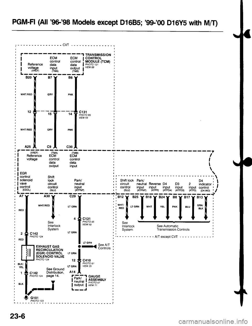
PGM-FI (All '9G'98 Models except Dl685; '99r0O D16y5 with M/T)
TRANSMISSIONCONTROLMODULE (TCM)
llEv/ 69
ECM ECMcontrol controlReference data datavollage inDutNREF) OMA}:q{.J
(VREF) OMA) OMB)Reference ECM ECMcontroldatajnput
EGRcontrol shift' I solenoid
i
-l
"""'"x :i1",'
sofenoid lock Pa(klvave Circult neutr; I vave circuit neutral| | control control inPut, ! (EsOLr {sru, (A}FNP):L------
voltag€ controldataoutput
I
{
ta
i;;;;';;
."
*
'i\,
' circuit neutral Reverse D4 D3 2 indtcator, ;' control input input input input input control | -,| (sLU) rAlPNPr TATPFI {ATpO4i dlPD3) tAfPzr rDa rNDl | /
[J=:ITTIT'{t
' Interlock See Automatrc: Svstem Transmission Controls I
i i controt
i
"'J;:;;,.,"^,
!
l1l
"lL
:1,.
i
".f:;;,.,"^, 1.,."n,
: I lt ti.."stEBkTJBi ""il*l"*
: | /" I SOLENOTD VALVE
i \J PHaro 12a I
i
t'i!",,,
Bi"ifit**1
';
i l ;;;a ',, pase 14 !'#$tl ii{"Ff*,
i
*-1.
---f !.gg1mr..
' 4 cror| - PHAfO 123
23-6
Page 1922 of 2189
Gruise Control (cont'd)
- How the Circuit Works
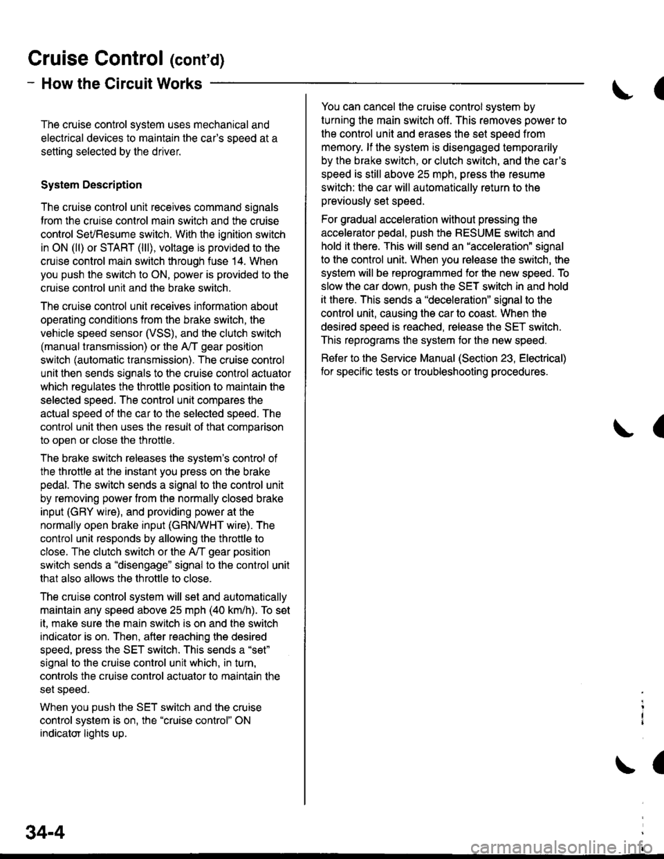
The cruise control system uses mechanical and
electrical devices to maintain the car's sDeed at a
setting selected by the driver.
System Description
The cruise control unit receives command signals
from the crurse control main switch and the cruise
control SeVResume switch. With the ignition switch
in ON (ll) or START (lll), voltage is provided to the
cruise control main switch through fuse 14. When
you push the switch to ON, power is provided to the
cruise control unit and the brake switch.
The cruise control unit receives information about
operating conditions from the brake switch, the
vehicle speed sensor (VSS), and the clutch switch
(manual transmission) or the A,/T gear position
switch (automatic transmission). The cruise control
unit then sends signals to the cruise control actuator
which regulates the throttle position to maintain the
selected speed. The conlrol unit compares the
actual speed of the car to the selected speed. The
control unit then uses the result of that comoarison
to open or close the throttle.
The brake switch releases the system's control of
the throttle at the instant you press on the brake
pedal. The switch sends a signal to the control unit
by removing power from the normally closed brake
input (GRY wire), and providing power at the
normally open brake input (GRN/vVHT wire). The
control unit responds by allowing the throttle to
close. The clutch switch or the A,/T gear position
switch sends a "disengage" signal to the control unit
that also allows the throttle to close.
The cruise control system will set and automatically
maintain any speed above 25 mph (40 km/h). To set
it, make sure the main switch is on and the switch
indicator is on. Then, after reaching the desired
speed, press the SET switch. This sends a "set"
signal to the cruise control unit which, in turn,
controls the cruise control actuator to maintain the
set speed.
When you push the SET switch and the cruise
control system is on, the "cruise control" ON
indicator lights up.
34-4
(
You can cancel the cruise control system by
turning the main switch off . This removes power to
the control unit and erases the set speed from
memory. lf the system is disengaged temporarily
by the brake switch, or clutch switch, and the car's
speed is still above 25 mph, press the resume
switch: the car will automatically return to the
previously set speed.
For gradual acceleration without pressing the
accelerator pedal, push the RESUME switch and
hold it there. This will send an "acceleration" signal
to the control unit. When you release the switch, the
system will be reprogrammed for the new speed. To
slow the car down. oush the SET switch in and hold
it there. This sends a "deceleration" signal to the
control unit, causing the car to coast. When the
desired speed is reached, release the SET switch.
This reprograms the system tor the new speed.
Refer to the Service Manual (Section 23, Electrical)
tor specific tests or troubleshooting procedures.
(
a
Page 1983 of 2189
A/T Gear Position Indicator (conrd)
- How the Circuit Works
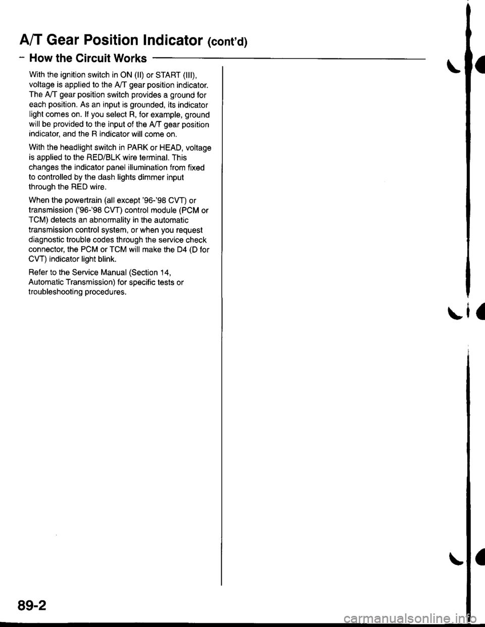
With the ignition switch in ON (ll) or START (lll),
voltage is applied to the A,/T gear position indicator.
The A,/T gear position switch provides a ground for
each position. As an input is grounded, its indicator
light comes on. lf you select R, for example, ground
will be provided to the input of the A,/T gear position
indicato( and the R indicator will come on.
With the headlight switch in PARK or HEAD, voltage
is applied to the RED/BLK wire terminal. This
changes the indicator panel illumination from fixed
to controlled by the dash lights dimmer input
through the RED wire.
When the powertrain (all except '96-'98 CVT) or
transmission ('96198 CVT) control module (PCM or
TCM) detects an abnormality in the automatic
transmission control system, or when you request
diagnostic trouble codes through the service check
connector, the PCM or TCM will make the D4 (D for
CVT) indicator light blink.
Refer to the Service Manual (Section 14,
Automatic Transmission) for specific tests or
troubleshooting procedures.
\ia
89-2
Page 2085 of 2189

25. Lower Left Rear of Engine
Component Location
\28. Lower Right Side of Engine Compartment
26. Left Side of Engine (All Except 816A2)29. Lower Right Front of Engine
\
27. Right Front of Engine30. Lower Front of Transmission
201-4
\
Page 2101 of 2189

Gomponent Location
121. Behind Left Kick Panel ('96-'98 CVT)\124. Rear of Engine Compartment (CVT)
TRANSMISSIONCONTROL MODULE(rcM)
122. Right Side Lower Engine Compartment (CVT)125. Behind Right Side of Dash Panel
\
123. Right Front of Engine (CVT)126. Underside of Hatch Lid
k
2A1-20
\
Page 2114 of 2189
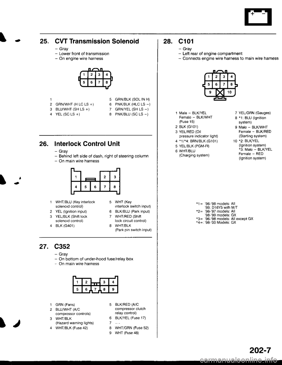
-25. CW Transmission Solenoid
- Gray- Lower front of transmission- On engine wire harness
1
2 GRNAVHT (H LC LS +)
3 BLUAVHT (SH LS +)
4 YEL (SC LS +)
5
6
7
8
GRN/BLK (SOL IN H)
PNK/BLK (HLC LS _)
GRN|VEL (SH LS -)
PNK/BLU (SC LS _)
26. Interlock Control Unit
- Gray- Behind left side oJ dash, right of steering column- On main wire harness
1
7
2
3
4
WHT/BLU (Key interlocksolenoid control)
YEL (lgnition input)
YEUBLK (Shift locksolenoid control)
BLK (G401)
WHT (Key
interlock switch input)
BLKBLU (Park lnput)
WHT/RED (Shinlock circuit control)
WHI/BLK(Park pln switch input)
6
7
27. C352
- Gray- On bottom of under-hood {use/relay box- On main wire harness
1
789
I
1
2
3
4
GRN (Fans)
BLUAVHT (fuC
compressor controlS)
WHT/BLK(Hazard warning lights)
WHT/BLK (Fuse 42)
BLKRED (A/Ccompressor clutchrelay control)
BLK,/YEL (Fuse 17)
WHT/GRN (Fuse 52)
WHT (Fuse 48)
6
7
8
I
28. C101
- Gtay- Left rear of engine compartment- Connecls engine wire harness to main wire harness
1 l\,4ale - BLK/YELFemale - BLK,ryVHT(Fuse 15)
2 BLK (G101)
3 YEURED (Oilpressure indicator light)
4 *1/*4: BRN/BLK (G101)
5 YEUBLK (PGI\4,FD
6 WHT/BLU(Charging system)
7 YEL/GRN (Gauges)
I *1: BLU (lgnition
sYstem)
9 Male - BLK VHTFemale - BLKRED(Slarting system)
10 *2: BLKryEL(lgnition system)*3: Male - BLK/YELFemale - RED(lgnition system)
*1= 96-'98 models: All'99: D16Y5 with M,iT*2= '96-'97 models: All'98-'99 modelsr GX*3= '96-'98 models: All except GX*4=: '98''00 Models: GX
202-7