1998 HONDA CIVIC The connector for a vehicle speed sensor
[x] Cancel search: The connector for a vehicle speed sensorPage 355 of 2189
Troubleshooting
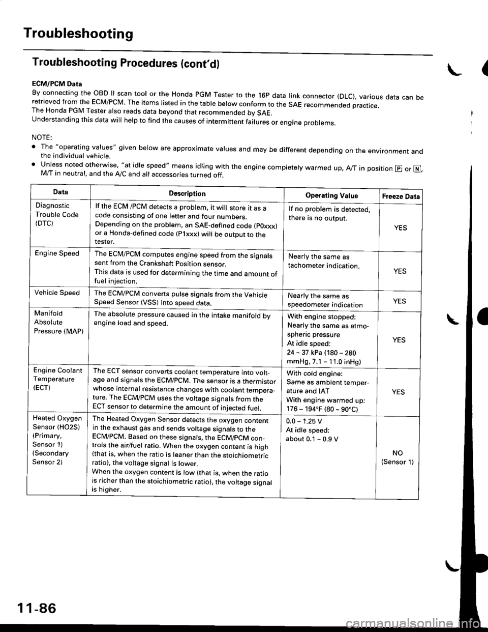
Troubleshooting Procedures (cont,dl
ECM/PCM Data
By connecting the OBD ll scan tool or the Honda pGM Tester to the l6p data link connector (DLC), various data can beretrieved from the EcM/PcM. The items Iisted in the table below conform to the sAE recommended practice.The Honda PGM Tester also reads data beyond that recommended bv SAE.understanding this data wil help to find the causes of intermittent fairures or engine probrems,
NOTE:
' The "operating values" given below are approximate values and may be different depending on the environment andthe individual vehicle.. Unless noted otherwise, "at idle speed,, means idling with the engine completely warmed up, Ay'T in position @ or E],M/T in neutral, and the Ay'C and all accessories turned off.
(
DataDescriptionOperating ValueFreeze Data
Diagnostic
Trouble Code(DTC)
lf the ECM /PCM detects a problem, it will store it as acode consisting of one letter and four numbers.Depending on the problem, an SAE-defined code (poxxx)or a Honda-defined code (Plxxx) will be outDut to therester.
lf no problem is detected,
there is no output.
YES
Engine SpeedThe ECM/PCM computes engine speed from the signalssent from the Crankshaft Position sensor.This data is used for determining the time and amount offuel injection,
Nearly the same as
tachometer indication.YES
Vehicle SpeedThe ECM/PCM converts pulse signals from the VehicleSpeed Sensor (VSS) into speed data.Nearly the same as
speedometer indicationYES
Manifold
Absolute
Pressure {MAP)
The absolute pressure caused in the intake manifold bvengine load and speed.With engine stopped:
Nearly the same as atmo-
spheflc pressure
At idle speed:
24 - 31 kPa (180 - 280
mmHg, 7.1 - 11.0 inHg)
YES
Engine Coolant
Temperature
(ECT)
The ECT sensor converts coolant temperature into volt_age and signals the ECM/PCM. The sensor is a thermistorwhose internal resistance changes with coolant temDera_ture. The ECM/PCM uses the voltage signals from theECT sensor to determine the amount of iniected fuel.
With cold engine:
Same as ambient temper,
ature and IAT
With engine warmed up:
176 - 194.F (80 - 90.C)
YES
Heated Oxygen
Sensor {HO2S)(Primary,
Sensor 1)(Secondary
Sensor 2)
The Heated Oxygen Sensor detects the oxygen contentin the exhaust gas and sends voltage signals to theECI\4/PCM. Based on these signats, the ECM/pCM con_trols the airlfuel ratio. When the oxygen content is high(that is, when the ratio is leaner than the stoichiometricratio), the voltage signal is lower.When the oxygen content is low (that is, when the ratiois richer than the stoichiometric ratio), the voltage signalis higher.
0.0 - 1.25 V
At idle speed:
about 0.1 - 0.9 V
NO(Sensor 1)
1 1-86
Page 359 of 2189
Troubleshooting
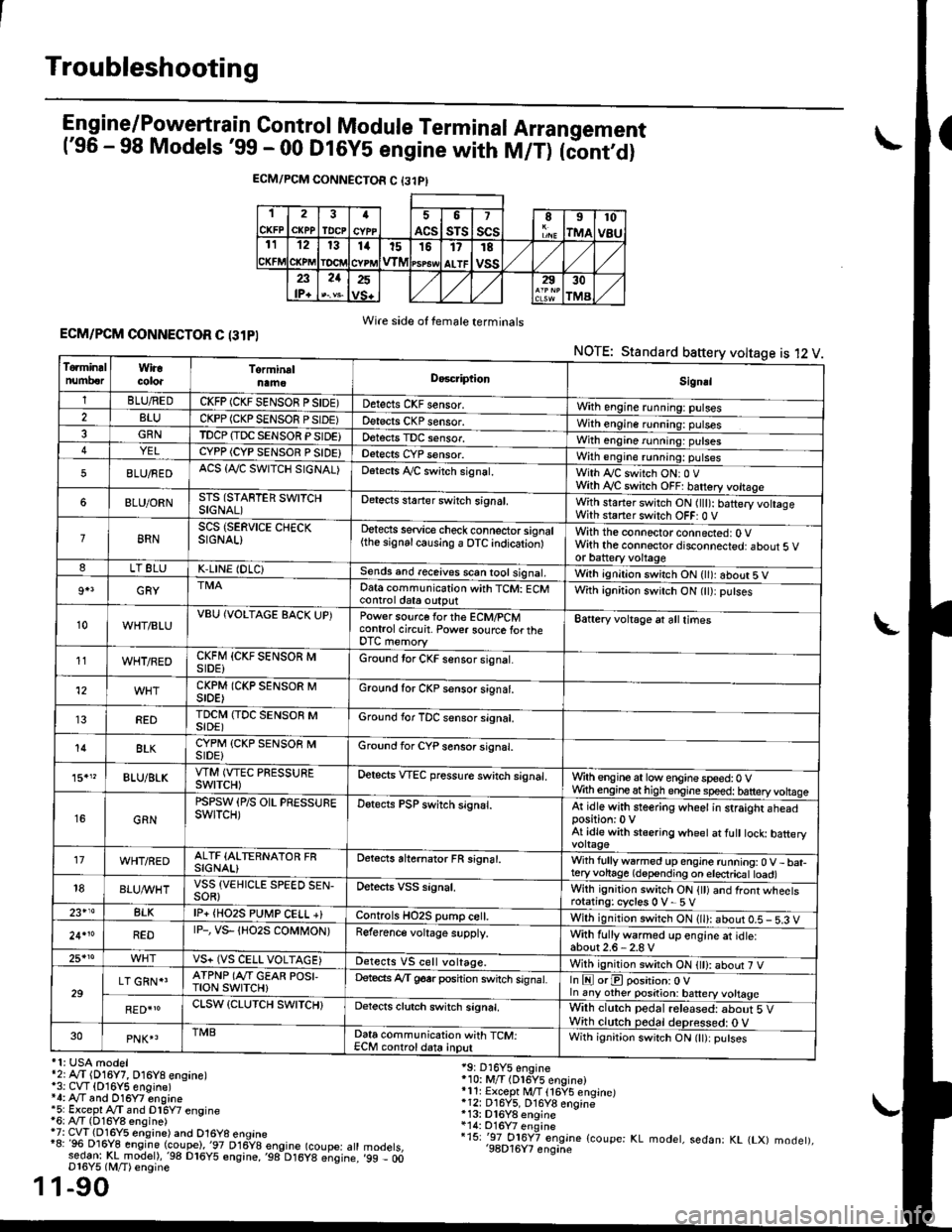
Engine/P_o_wgrtrain Control Module Terminal Arrangement('96 - 98 Models '99 - 00 Dt6y5 engine with M/T) tc'oniOi
ECM/PCM CONNECTOR C {31PI
1
CKFP
2
CXPPTDCPa
ACS
5
sTs
7
scsII
rMA
10
v8u121314t51517
ALTF
TE
vss23lP+
21252930
TMA
Wire side of female terminalsECM/PCM CONNECTOR C (31PI
NOTE: Standard baftery voltage is 12 V
'1: USA modelr2rA,.T (D16Y7, O16Y8 ensane)*3: CVT (O16Y5 engine)*4: Ay'T and O16Y7 engine'5: Excepl A./T snd Dl6Y7 engine16: Ay'T (D16Y8 ensine){7: CVT (Dl6Y5 eosine) and O16Y8 enoine"8: 96 Dl6Y8 engine (coupe),'97 D16y8 engine (coupe: atl:ed-9I t!!rnodelr,'98 D16y5 ensine,,98 D16y8 e;sine.D16Y5 lM/T) ensine
1-90
19: D16Y5 engine'10: M/T (Dl6Y5 engine)*11r Except M/T 116Y5 engine)*12: D16Y5, D16Y8 engine*13: Dl6Y8 enqine*14: O16Y7 enginei15: '-97 O16Y7 engjne (coupe: KL modet, sedan: KL (LX) modet),'98D16Y7 enqine'99 - 00
1
To.min!lnumberWiracoloaTorminalnameDo6criptlonSignal
1BLU/REDCKFP (CKF SENSOR P SIDE)Detects CKF sensor.With engine running: pulses2BLUCKPP (CKP SENSOF PSIDE)Detects CKP sensor.With engine running: pulses3GRNTDCP {TDC SENSOR PSIDE}Detects TDC sensor,With engine running: putses4YELCYPP (CYP SENSOR P SIDE)Detects CYP sensor.With engine running: pulses
5BLU/FEDACS {Tr'C SWITCH SIGNAL)Detects ,ay'C sw;tch signat.With Iy'C switch ONr 0 VWith Ay'C switch OFF: batrery vottage
6BLU/ORNSTS (STARTER SWITCHSIGNAL)Detects staner swilch signal,With staner switch ON ltlt): batery vohageWith staner switch OFF: 0 V
8RNSCS (SERVICE CHECKSIGNAL)Detects service check connector signal{the signalcausing a OTC indicationlWith the connector connected: O Vwith the connector disconnected: about 5 vor battery voltageLT 8LUK,LINE (DLC)Sends and receives scan iool signal,Wirh ignition switch ON { ): about 5 V
9+3GRYDat6 communication with TCM: ECMcontrol ctat6 outputWith ignition switch ON (tt):putses
10WHT/BLUVBU (VOLTAGE BACK UP)Power source forthe ECM/PCMcontrol circuit. Power sourc€ lortheDTC memory
Battery voltage at all times
11WHT/REDCKFM {CKF SENSOR MSIDE)Ground tor CKF sensor signal.
12CKPM (CKP SENSOR MSIDE)Ground for CKP sensor s;gnat.
REDTDCI\4 (TDC SENSOR MSIDE)Ground for TDC sensor signal.
14BLKCYPM (CKP SENSOB MSIDE}Groond for CYP sensor signal.
15."BLU/BLKVTM (VTEC PRESSUREswtTcH)Oetscts VTEC pressure switch signal.Wrth engine at low enginespeed:0 VWth engineathigh engine speed: tatteryvoltase
16GRN
PSPSW (P/S OIL PRESSUREswtTcH)Detects PSP switch signal.At idle with steering wheel in straight aheadposition:0 VAt idle with stsering wheet at fult tock batteryvoltage'17WHT/REDALTF (ALTERNATOR FRSIGNAL)Detects ahernator FR signal.With fullyw6rmed up engine running:0 V- bat-teryvohage (depending on electricat toad)18BLUI/VHTVSS {VEHICLE SPEED SEN-SOR}Oetects VSS signal.Whh ignitjon switch ON {tt) and front wheetsrotating: cycles 0 V- 5 V23+14BLKlP+ {HO2S PUtr4P CELL +}Controls HO2S pump ce .With ignition switch ON (ll): abour 0.5 - 5.3 V
24.10REDrP-, vs- {Ho2s coMt oN)Reference voltage supply.With fullywarmed up engine et idle:about2.6-2.8 V25*roVS+ (VS CELL VOLTAGE)Detects VS cell voltage.With ignition switch ON t): abour 7 V
29LT GRN*'ATPNP (Ar'T GEAR POSI,TroN swrTcH)Deteds Ay'T g6srposhion switch signat.In E orE position: O Vln any other position: battery vottage
RED{roCLSW (CLUTCH SWITCH}Detects clutch switch signal,Wilh clutch pedal released: about 5 VWith clutch pedal deDressed: O V30PNK4TMBData communication with TCM:ECM controldata inputWith ignit;on switch ON (lt):putses
Page 365 of 2189
Troubleshooting
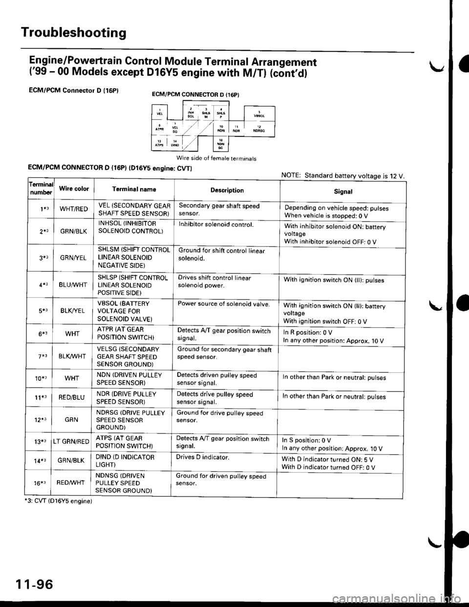
En gine/P_oweft ra in Control Module Termina I Arran gement
('99 - 00 Models except Dl6YS engine with M/Tl (cont,dl
ECM/PCM Connectol D (16P1
Wire side of female terminats
ECM/PCM CONNECTOR D {16P) (Dl6YS engine: CVTI
*3: CVT (Dl6Y5 engine)
NOTE: Standard battery voltage is 12 V
ECM/PCM CONNECTON D (r6P)
f€rminal
numDeaWire colorTerminalnameDescriptionSignal
1+3WHT/REDVEL (SECONDARY GEARSHAFT SPEED SENSOR)
Secondary gear shaft speedsensor,Depending on vehicle speed: pulsesWhen vehicle is stopped:0 V
2*3GRN/BLK
INHSOL {INHIBITORSOLENOID CONTROL)Inhibitor solenoid control.With inhibitor solenoid ON: bafteryvoltageWith inhibitor solenoid OFF: 0 V
3+3GRN/YEL
SHLSM (SHIFT CONTROLLINEAR SOLENOID
NEGATIVE SIDE)
Ground for shift control linearsolenoid.
BLU^/vHTSHLSP (SHIFT CONTROLLINEAR SOLENOIDPOSITIVE SIDE}
Drives shift control linearsolenoid power.With ignition switch ON (tl): pulses
5*3BLK,/YE LVBSOL lBATTERYVOLTAGE FOR
SOLENOID VALVE)
Power source of solenoid valve.With ignition switch ON (ll): baneryvoltage
With ignition switch OFF: 0 V
6*3WHTATPR (AT GEAR
POSITION SWITCH)Detects A,/T gear position switchsrgnal.InRposition:0V
In any other position: Approx. 10 V
BLKA/VHIVELSG (SECONDARY
GEAR SHAFT SPEEDSENSOR GROUND)
Ground for secondary gear shaftspeed sensor.
10*.WHTNDN (DRIVEN PULLEY
SPEED SENSOR)
Detects driven pulley speedsensor srgnal.In other than Park or neutral: pulses
11*3RED/BLUNDR (DRIVE PULLEY
SPEED SENSOR)
Detects drive pulley speedsensor srgnal.In other than Park or neutralt pulses
12*3GRNNDRSG (DRIVE PULLEYSPEED SENSORGROUND)
Ground for drive pulley speedsensor.
13*3LT GRN/REDATPS (AT GEARPOSITION SWITCH)
Detects Ay'T gear position switchsrgnal.In S position:0 VIn any other positioni Approx, 10 V
14*3GRN/BLKDIND 1D INDICATOR
LIGHT)
Drives D indicator.With D indicator turned ON: 5 VWith D indicator turned OFF: O V
16*rRED^/VHTNDNSG (DRIVEN
PULLEY SPEEDSENSOR GROUND)
Ground for driven pulley speedsensor.
1 1-96
Page 374 of 2189

3.
5.
6.
1.
Fuel Cut-off Control
. During deceleration with the throttle valve closed, current to the fuel injectors is cut off to improve fuel economy at
speeds over the following rpm:. D16Y5 engine (M/T):850 rpm. D]6Y5 engine (CVT), D'16Y8 engine (USA M/T): 920 rpm
. Dl6Y8 engine (USA A,/I), D16Y7 engine (USA A,/T);910 rpm
. D16Y8 engine (Canada M/T), D16Y7 engine (canada): 990 rpm
' D16Y8 engine (Canada M/T): 1,000 rpm
. 816A2 engine: 970 rpm
. Fuel cut-off action also takes place when engine speed exceeds 6,900 rpm (D16Y5, D16Y7 engine; D'16Y8 engine:
7,000 rpm. 816A2 engine: 8.100 rpm), regardless of the position of the throttle valve, to protect the engine from
over-rewing. With '99 Dl6Y7 engine (A,/T) and '99 D16Y8 engine (A./T), the PCM cuts the fuel at engine speeds over
5,000 rpm when the vehicle is not moving.
IVC Compressor Clutch Relay
When the ECM/PCM receives a demand for cooling from the air conditioning system, it delays the compressor from
being energized, and enriches the mixture to assure smooth transition to the A,/C mode
Evaporative Emission (EVAP) Purge Control Solenoid Valve*'
When the engine coolant temperature is above 154'F (68'C). the ECM/PCM controls the EVAP purge control solenoid
valve which controls vacuum to the EVAP purge control canister.
Evaporative Emission (EVAP) Purge Control Solenoid Valve*a
When the engine coolant temperature above 154"F (68"C), intake air temperature above 32"F (0'C) and vehicle speed
above 0 mile (0 km/h) or [Ay'C compressor clutch on and intake air temperature above 160"F (41'C)], the ECM/PCM
controls the EVAP purge control solenoid valve which controls vacuum to the EVAP purge control canister.
Exhaust Gas Recirculation (EGR) Control Solenoid Valve*?
When EGR is required for control of oxides of nitrogen (NOx) emissions. the ECM controls the EGR control solenoid
valve which supplies regulated vacuum to the EGR valve
Alternator Control
The system controls the voltage generated at the alternator in accordance with the electrical load and driving mode,
which reduces the engine load to improve the fuel economy.
ECM/PCM Fail-safe/Back-up Functions
1. Fail safe Function
When an abnormality occurs in a signal from a sensor, the ECM/PCM ignores that signal and assumes a pre-pro-
grammed value for that sensor that allows the engine to continue to run.
2. Back-uD Function
When an abnormality occurs in the ECM/PCM itself, the fuel injectors are controlled by a back-up circuit independent
of the system in order to permit minimal driving.
3. Self diagnosis Function lMalfunction Indicator Lamp (MlL)l
When an abnormality occurs in a signal from a sensor, the ECM/PCM supplies ground for the lvllL and stores the DTC
in erasable memory. When the ignition is initially turned on, the ECM/PCM supplies ground for the MIL for two sec-
onds to check the MIL bulb condition.
4. Two Trip Detection Method
To prevent false indications, the Two Trip Detection Method is used for the HO2S, fuel metering-related. idle control
system, ECT sensor, EGR system and EVAP control system self-diagnostic functions. When an abnormality occurs,
the ECM/PCM stores it in its memory. When the same abnormality recurs after the ignition switch is turned OFF and
ON 0l) again, the ECM/PCM informs the driver by lighting the MlL. However, to ease troubleshooting, this function is
cancelled when you jump the service check connector. The MIL will then blink immediately when an abnormality
occurs,
5. Two (or Three) Driving Cycle Detection Method
A "Driving Cycle" consists ot starting the engine. beginning closed loop operation, and stopping the engine. lf misfir-
ing that increases emissions is detected during two consecutive driving cycles, or TWC deterioration is detected dur-
ing three consecutive driving cycles, the ECM/PCM turns the MIL on. However, to ease troubleshooting, this function
is cancelled when you jump the service check connector. The MIL will then blink immediately when an abnormality
occurs.
(cont'd)
1 1-1 05
.1.
Page 445 of 2189
PGM-FI System
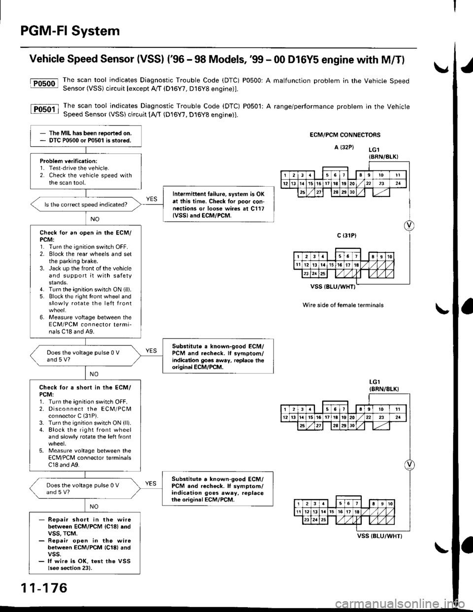
Vehicle Speed Sensor (VSSI ('96 - 98 Models,'99 - 00 D16Y5 engine with M/Tl
@The scan tool indicates Diagnostic Trouble Code (DTC) P0500: A malfunction problem in the Vehicle SpeedSensor (VSS) circuit Iexcept A!/T (D16Y7, D16Y8 engine)1.
The scan tool indicates Diagnostic Trouble Code (DTC) P0501: A range/performance problem in the VehicleSpeed Sensor (VSS) circuit [A,rT {D16Y7, D16Y8 engine)].
ECM/PCM CONNECTORS
A {32P} LG.t
VSS IBLU/WHT}
Wire side ot temale terminals
LGI(BRN/8LK}
The MIL has been reDorted on.DTC P0500 or P0501 is stored.
Problem verification:1- Test drive the vehicle.2. Check the vehicle speed withthe scan tool.
Intermittent tailure, system is OKat this time. Check tor Door con-nections or loose wires at C117{VSSland ECM/PCM.
ls the correct speed indicated?
Check for an open in the ECM/PCM:1. Turn the ignition switch OFF.2. Elock the rear wheels and setthe parking brake.3. Jack up the front of the vehicleand support it with safetystands.4. Turn the ignition switch ON (ll).
5. Block the right tront wheel andslowly rotate the left front
6, Measure voltage between theECM/PCM connector termi-nals C18 and A9.
Subslitute a known-good ECM/PCM and recheck. lf symptom/indic.tion goes away, replace theorisinal ECM/PCM.
Does the voltage pulse 0 Vand 5 V?
Check tor a short in ihe ECM/PCM:1. Turn the ignition switch OFF.2. Disco n n ect the ECM/PCMconnector C (31P).
3. Turn the ignition switch ON {ll).4. Block the right front wheeland slowly rotate the left front
5. Measure voltage between theECM/PCM connector terminalsC18 and A9.
Substitute a known-good ECM/PCM and recheck. lI symptom/indication goes away. replacethe original ECM/PCM.
Does the voltage pulse 0 Vand s V?
- Repair short in the wirebetwGen ECM/PCM {C18} endvss, TcM.- Repair open in the wirebetween ECM/PCM {Cl8} andvss.- lf wire is OK, test the VSSlsee section 23).
{BRN/BLK}
239l0lt
121611t8t9202321
2A2930
c {31P}
I38191o
tl12ialr5i6l10./
I2356a9l011
12l3l5t61tl8t920222a
27202930
12910
t2l13l.l7I l,/ 1,/231r.lslt., ),rlL
VSS {BLU/WHT}
11-176
Page 446 of 2189

fFosoo-l
lFosoil
Vehicle Speed Sensor (VSS) ('99 - 00 Models except Dl6Y5 engine with M/T)
Thescantoo|indicatesDiagnosticTroub|ecode(DTc)Po5o0:Ama|functionproblemintheVehic|espeed
Sensor (VSS) circuit lexcept A//T (D16Y/, D16Y8 engine)l'
Thescantoo|indicatesDiagnost|cTroub|eCode(DTC)Po5o1:Arange/performanceprob|emintheVehicle
SDeed Sensor {VSS) circuit tA,/T (D16Y7, D16Y8 engine)1.
ECM/PCM CONNECTORS
B {25P)
I
t
Wire side ol lemale terminals
ECM/PCM CONNECTORS
B E5PI
The MIL has been reported on
OTC P0500 or P0501 is stored.
Problem veritication:1. Test-drive the vehicle.
2. Check the vehicle speed with
the scan tool
lntermitt6nt failure, sYstem is OK
at thb time. Check tor Poor con-
nections or loose wir6 at C117
{vss} .nd ECM/PCM
ls the correct sPeed indicated?
Check for an open in the ECM/
PCM:1. Turn the ignition switch OFF.
2. Block the rear wheels and set
the parking brake
3. Jack uP the front ofthe vehicle
and support it with safety
stands.4. Turn the ignition switch ON (ll).
5. Block the right front wheel and
slowly rotate the left front
6, Measure voltage between the
ECM/PCM connector termi_
nals C23 and 820.
Substituto a known'good ECM/
PcM and rech€ck. ll sYmptom/
indic€tion goes awaY, lsplace the
original ECM/PCM.
Does the voltage Pulse 0 V
and 5 V or battery voltage?
Check for a short in the ECM/
PCM:1. Turn the ignition switch OFF.
2. Disco n n ect the EcM/PcM
connector C (31P).
3. Turn the ignition switch ON (ll)
4. Block the right front wheel
and slowly rotate the left front
5. Measure voltage between the
ECM/PCM connector terminals
C23 and 820.
Substiiute . known-good ECM/
PCM and r6check. lf symptom/indication goes awaY, rePlace
the origin.l ECM/PCM.
Does the voltage Pulse 0 V
and 5 V or battery voltage?
- Reoair short in the wire
between ECM/PCM {C23} and
vss. TcM.- Repai. open in the wire
between ECM/PCM {C231 andvss.- lf wire is OK, tesr the VSS
{see sestion 23).
Wire side oI female terminals
11-177
Page 525 of 2189

Emission Control System
Exhaust Gas Recirculation (EGR) System (D16Y5 engine with GWI (cont'dl
lTl49il T_he scan tool indicates Diagnostic Trouble Code (OTC) P1491: A malfunction in the Exhaust Gas Recirculation- lEgh) svstem.
CvT lM/T see page 1l-2611:
J
EGR VALVELIFT SENSOR#16 HOSE
PUMP/GAUGE,0- 30 in.HsA973X-041-XXXXX
EGRVALVE
The MIL has been reoorted on.DTC P1491 is stoled.
Problem verification:1. Do the ECM/PCM Reset Proce-du re.2. Connect the SCS service con'
3. Start the engine. Hold theengine at 3,000 rpm with noload {in Park or neutral) untilthe radiator fan comes on,4. Drive the vehicle on the roadfor approx. 10 minutes. Try tokeep the engine speed in the1,700 - 2,500 rpm range.
Intermittonl failure, system is OKat this time. Check for Door con-nections or loose wires at, C144{EGR velve} and ECM/PCM.
ls DTC P l49l indicated?
Check fo. vacuum to ihe EGR
1. Disconnect the No. 16 hose fromthe EGR valve.2. Connect a vacuum pump/gauge to the hose.3. Start the engine and let it idle.
ls there any vacuum?
Check tor a malfunction in theEGR control solenoid valve:'1. Disconnect the EGR controlsolenoid valve 2P connector,2. Becheck the No. 16 hose for
Check vacuum hose routing o,the entire EGR svstem. lf hoserouting is OK, replac€ the EGRcontrol solenoidvalv6.
ls there any vacuum?
Substitute a known-good ECM/PCM and recheck. It symptom/indicalion goes away, replacethe original ECM/PCM.
(To page 11 257)
11-256
Page 721 of 2189
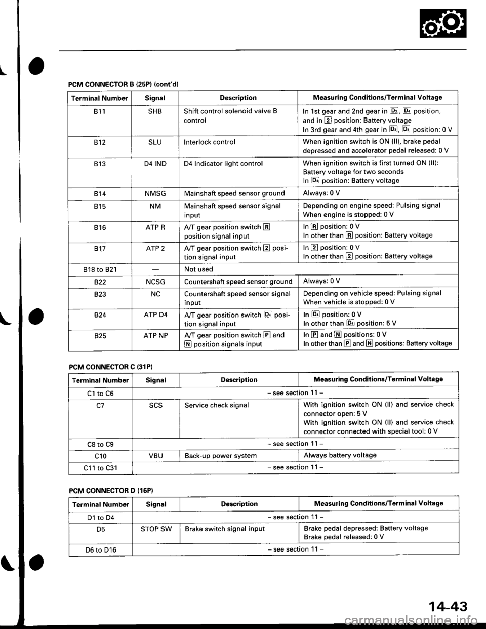
I
PCM CONNECTOR B {25P1 {cont'dl
Terminal NumberSignalDescriptionMeasuring Conditions/Terminal Vohage
811SHBShift control solenoid valve B
control
In 1st gear and 2nd gear in -q1, q11 position,
and in E] position: Battery voltage
In 3rd gear and 4th gear in lD.J, [Dr- position: 0 V
B't2SLUInterlock controlWhen ignition switch is ON (ll), brake pedal
deoressed and accelerator Dedal released: 0 V
813D4 INDD4 Indicator light controlWhen ignition switch is first turned ON (ll):
Battery voltage for two seconds
In E position: Baftery voltage
B't 4NMSGMainshaft speed sensor groundAlways: 0 V
E tcNMMainshaft speed sensor signal
input
Depending on engine speed: Pulsing signal
When engine is stopped: 0 V
816ATP RAy'T gear position switch Eposition signal input
InE position: 0V
In other than E position: Battery voltage
817ATP 2A/T gear position switch E posi-
tion signal input
InE position: 0V
In orher than E position: Battery voltage
818 to 821Not used
s22NCSGCountershatt speed sensor groundAlwaysr 0 V
B�23NCCountershaft speed sensor signal
input
Depending on vehicle speed: Pulsing signal
When vehicle is stopped: 0 V
B�24ATP D4Ay'T gear position switch lor posi-
tion signal input
InEposition:0V
In other than 6 position: 5 V
ATP NPA,/T gear position switch E and
N position signals input
InE and E positions: 0V
In otherthan E and N] positions: Battery voltage
PCM CONNECTOR C {31P)
Terminal NumberSignalDescriptionMeasuring Conditions/Terminal Voltage
Cl to C6- see section 11 -
c1Service check signalWith ignition switch ON (ll) and service check
connector oDen; 5 V
With ignition switch ON (ll) and service check
connector connected with sDecial tool: 0 V
C8 to Cg- see section 11 -
c10VBUBack-up power systemAlways battery voltage
C11 to C31- see section '11 -
PCM CONNECTOR D (16P}
Terminal NumberSignalDescriptionMeasuring Conditions/Terminal Voltage
Dl to D4- see section 11 -
D5STOP SWBrake switch signal inputBrake pedal depressed: Battery voltage
Brake pedal released: 0 V
D6 to D16- see section 1 l -
14-43