Page 1953 of 2189
- How the Circuit Works
'96198 Models
The air delivery system directs the flow of air used
by the heater and air conditioner systems.
Mode Selection
Mode selection is controlled by the mode switches
in the heater control panel and the mode control
motor. When you select a specific mode, voltage is
applied through the dimming circuit to the LED,
which comes on, indicating the mode selected.
Ground is orovided to the mode control motor
though that mode switch. The motor then runs until
the air control door reaches the proper position.
Fresh/Recirculation 56lection
When you press the fresh or recirculation button, a
ground signal is sent from the heater control panel
to the recirculation control motor. The motor then
runs until the recirculation door reaches the proper
position. Battery voltage is also applied through the
dimming circuit to the corresponding LED, and the
LED comes on.
Refer to the Service Manual (Section 21, Heater) for
specitic tests or troubleshooting proc€dures.
'99J00 Models
The heater control panel receives battery voltage at
all times through fuse 47. With the ignition switch in
ON (ll), voltage is supplied to the heater control
panel through fuse 17. The control panel is
grounded at G402.
The heater control panel controls the air delivery
motors, and supplies a 5 VDC reterence voltage to
the air mixture control motor.
The air mixture and mode control motors each
receive inputs trom the heater control panel. The air
mix motor regulates the mixture of cold and hot air
by varying the position of the heater-evaporator doot
The mode control motor controls the direction and
volume of outlet air. The air flow can be directed to
the dashboard vents or the corner vents.
Both the air mixture control molor and mode control
motor are grounded by the h€aler control panel.
The recirculation control motor receives battery
voltage through fuso 17 when the ignition swilch is
in ON (ll). lt regulates the position of the fresh/recirc
door, and is controlled by two position inputs from
the heater control panel ("Recirc" and "Fresh").
Refer to the Service Manual (Section 21, Heater) tor
specific tests or troubleshooting procedures.
61-3
Page 1956 of 2189
AiC Compressor Gontrols (cont'd)
- '99-'00 Models
From page 62.
v
I*"-ilii.,"r,
ihtli4
BLUAVHT
15
6LUAVHT
UNDER.HOODFUSE/RELAYBOX
Seg Pow6rDistrlbutiofl,pag€ 'l Gl1-c353PHO|O 8
l[,,*
';.!, "'""
,c,/cSwitch switchcommon itput
a,/cTHERMOSTATOlt below3"C (37"F).
THERMISTOR
(
B11A A8A B'IO |'r--:=---I A/C lgnition B€ttery II request input (backup) :
".j:[ru*,,ry "..;X
{;[
vtEW 57
HEATERCONTROLPANEL
l'lCswitch SwitchLgD IEDcodrol cormonGrouod
See AirD€livery,RgarWindowD€foggar
BIK
cl
ORN
c5
GBN
r,/cOt'llndicatof
HEATERPUSHswrTcHEs
t/cSwltch
S€e AirDelivefy,RearWindowDslogg6f
See GroundDist.ibdion,page 1,1-5.
Y
I(
=ffi;
(
.I UNDER.
I HOODi FUSE/I RELAYI Box
IJ
62-2
PHOfO 125
Page 1957 of 2189
- How the Circuit Works
Battery voltage is supplied through tuse 56 to the
A,/C compressor clutch r€lay contacts at all times.
With the ignition switch in ON (ll), vollage is applied
to the coil of the A,/C compressor clutch relay
through fuse 17. When you push the A,/C switch
ON, and the heater fan switch is in position | , 2, 3,
or 4, a "ground" input is provided to the engine
control module (ECM) or powertrain control module
(PCM) through the l'lC thermostat and the l'lC
pressure switch.
The A,/C compressor clutch relay is grounded by the
engine control module (ECM) or powertrain control
module (PCM). When energized, the A'lC
compressor clutch relay allows battery voltage to
turn on the A,/C comDressor clutch.
The A,/C ON indicator light comes on when the A,/C
system is requested.
A,/C Thermostat
The A'lC thermostat is located on the evaoorator
housing. The A,/C thermostat turns off the A,/C
compressor clutch if the temperature at the
evaporator goes below 3'C (37'F). This prevents
condensation from freezing on the evaporator fins
and blocking the air delivery into the passenger
compartment. The blower motor will keep running
when the sensor turns off the comDressor.
A,/C Pressure Switch
The fuC oressure switch is located in the condenser
outlet line where refrigerant is in a high
temperature/high pressure liquid state. The switch
will sense abnormally high or low pressure, and
open the circuit. This removes ground, and the
compressor will stop running.
Thermal Protectot
The thermal protector, located on the A,/C
compressor, opens and turns the compressor off if it
senses high temperature. Once the compressor
cools, the switch will close and the compressor will
begin running again.
Refer to the Service Manual (Section 22,
Air Conditioning) for specific tests or
troubleshooting procedures.
62-3
Page 1960 of 2189
Fans (cont'd)
- '99-'00 Models
Switch"common
a,/cTHERMOSTATOff below3'C (37" F).
rla
iTm,il-- l5;i;T iln"lgg1
L_t]stE"_i*-o* !-J-___i
*-"'
"W"u'
".*L[F*f,l"' -*,".'"[ftT,;.'
I I .-.. Sse Power II ',-.', Sse Power I S€€ Pow€r
?+ 3s;iT:3:' ?'4 3ff:?f?l:
OEE I Dbfibution,
I pacp 10.9.
HEATERCONTROLPANEL
vlEw 76
A6
BLK
;+
::--
{***,Pase*11
ItI
rfa
r,/cswitchinputL-----
HEATERPUSHswtTcHEs
A/CSwlbh
See AirDslivery,n6arWindowDelogoor
S€e AltDeliv€ry,BaarWindowD€loggpr
See GroundDistribution,pag€ 1+5.
I
J;-a;
I I 'l rHERMrsroR I Ilt | 23 9--------------2, c723q/ f, ,2tr prtoroz!3a
tttlllnr ar-x,ver- | tn*t,".u IItI
orl "tol---riliii"--
inplt (backup)
i
I
Nclsvritcn Swikh ILED LEDcontrol cofrrnon Ground _ _.i
2Yl
^..._-_I t*-*"!
t2oV c723 I
- -_-\Tgr?;u L
---rF------
requ€si
63-2
a/cONlrdlcalqr
Page 1961 of 2189
- How the Circuit Works
Radiator Fan
Voltage is provided at all times to the radiator fan
relay (contacts) through fuse 57. With the ignition
swilch in ON (ll), voltage is provided to the coil of
the relay through luse 17.
The radiator tan relay can be grounded through
either the engine coolant temperature switch or the
engine control module (ECM) or powertrain control
module (PCM).
The engine coolant temperature switch grounds
the radiator fan relay (coil) when the engine
coolant temperature exceeds 199'F (83'C). The
switch opens when coolanl temperature
decreases 3'- 8'C.
Condenser Fan
Voltage is provided at all times to the condenser fan
relay (contacts) through fuse 56. With the ignition
switch in ON (ll), voltage is provided to the coil of
the relay through fuse 17. When you push the A'lC
switch and put the heater fan switch in 1, 2,3, o( 4
position, the ly'C thermostat comes on, the
condenser fan relay energizes, and the condenser
fan motor runs.
A,/C Thermostat
The A,/C thermostat is located on the evaporator
housing. The A,/C thermostat tums off the A/C
compressor clutch if the temperature at the
evaporator goes below 3'C (37'F). This prevents
condensation from freezing on the evaporator fins
and blocking the air delivery into the passenger
compartment. lf the temperature goes below 3'C
(37"F) tuming off the Ay'C thermostat, ground will be
removed from the condenser fan relay. This will
deenergize the relay and remove voltage from the
condenser fan motor causing the fan to stop running.
Reter to the Service Manual (Section 23, Eleckical)
for specific tests or troubleshooting procedures.
63-3
Page 1963 of 2189
- '99-'00Models
t@
J
See Power0istribution,pag€ 1&9.
r
I
I
Lc420
vtEw 53".*:.f
!
"T.I
FUSE '7HEJT'EF AIC RETAY7JA
UNDER-DASHFUSE/RELAYBOXPHOfO 58
r-r---1 UNDER-HOOD
| ( #tt* IFUsE/RELAY
I t sl*t-' '"o'o'
L-*----J3 Y C3s1
Ss6 Pows Dist bution,pag€ 10-9.
Sn itchLEDcommon
c420PHOTO 63vtEw 53
HEATERCONTROLPANEL
II
I
lgnition inpd
Swiich SlitohGroulld co{Y}rnon inMLEDgontrol
Rear winoow Idofogger Igl",,ry'_l
A6
ALX
S9a €roundDistr&dbn,P.go 1it-7.
c12
YEL
c9
BLK
r'
c6
PUR
c1
ORN
A7BLU/YEL
21
BLU/YEL
BLU/YEL
4(GX 10)
BLU/YEL
8
- Se€ Air ;D6livory
ONIndlcitor
wlIT/GFI{
c723PHO|O 138
c440PHO|O 81vtEw 45
c411PHOTO 60vtEw 60
c501
vtEwss 5
R€aIWlndowDcroggerSultch
56€ AirDeliv€ryL------- ---J
HEATER PUSH SWITCHESUNDEN.DASHFUSE/RELAYBOXPHO|O 5e
I
I
I
I
See GoundDistdbltion,page 14-7.
NEABwlNoolyDEFOGGENF€I.AYPrrolo 59
I
I
I
I
I
cssl
vtEw 47
Halchback
"*1[ ftTi.:-
wtNDowANTENNAcotL{cx'l) T 9,*%,,
",-"",-,
1
[93ff''n'*'
to!.'IFI REARI J I wrNDow
lll
DEFoGGER
".-i."tr ftTi",,'
t V F,9"oB ",erxialul I
ffiff$Eex,"
*"r'
I
I
* cttrPHOfO 10A
Sre GroundDFtrtbditm,pago 1+7.
I
t_
".":il
H
eY
82
ALK*-r"
arr<
-.1
!
S€9 GrolndDistribtdion,pag€ 1+ 10
*r: G401* csozG601
I. G,rc2
PHOIO 57
BEARwtNDowDEFOGGER
64-1
Page 1964 of 2189
Rear Window Defogger
- How the Circuit Works
'96198 Models
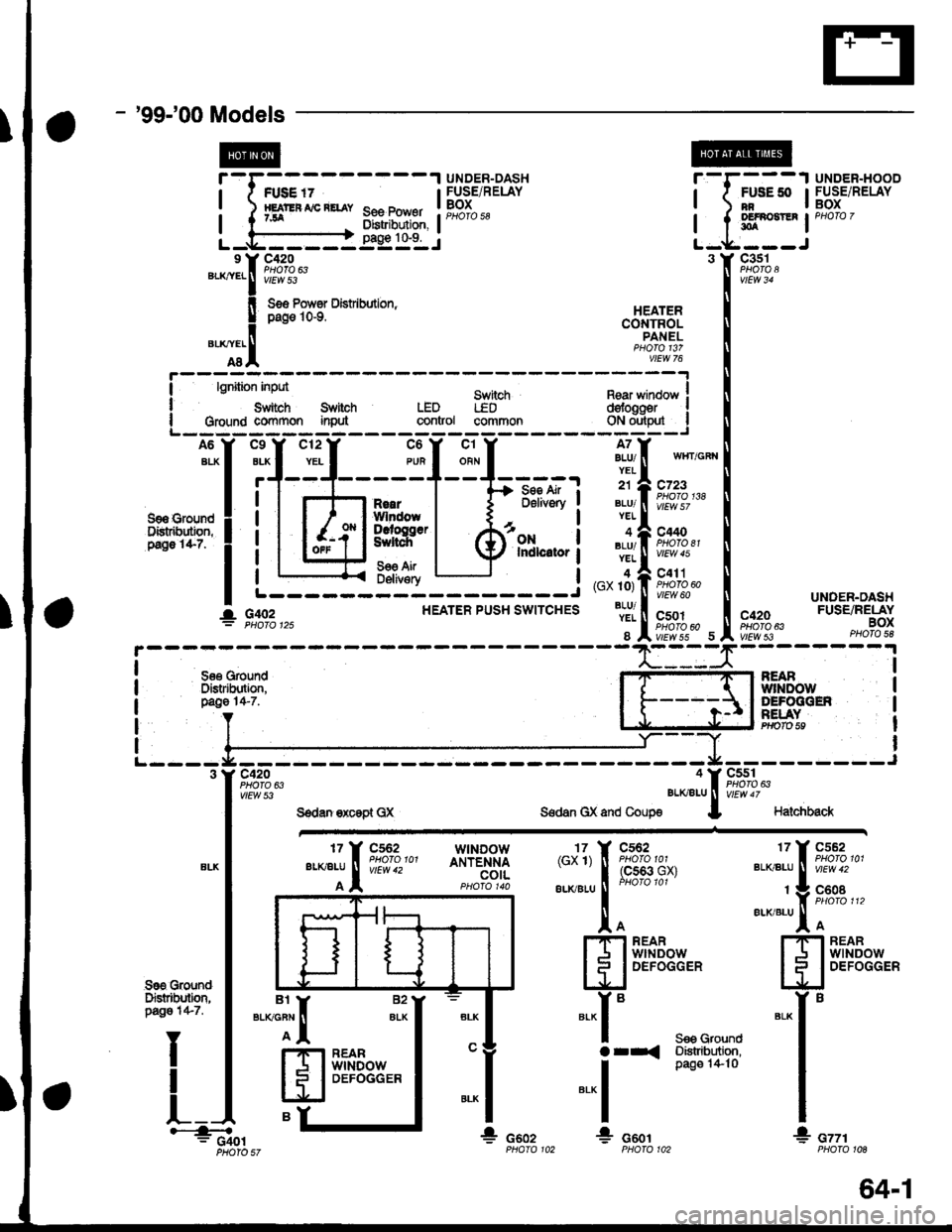
Voltage is applied at all limes through tuse 50 to the
rear window detogger relay (contacts). With the
ignition switch in ON (ll), voltage is applied through
tuse 16 to the rear window defogger switch.
When you turn the switch ON, voltage is applied to
the defogger timer circuit. The timer circuit supplies
voltage to the rear window defogger relay (coil). The
relay energizes and supplies voltage to the rear
window defogger. The defogger grid then heats the
rear window to remove any condensation from the
glass.
The defogger timer circuit will automatically turn off
the rear window defogger after about 25 minutes.
Refer to the Service Manual (Section 23, Electrical)
for specific tests or troubleshooting procedures.
'99100 Models
Voltage is applied at all times through fuse 50 to the
rear window delogger relay (contacts). With lhe
ignition switch in ON (ll), voltage is applied through
fuse 16 to the heater control oanel.
When you turn the rear window defogger switch
ON, a signal is sent to lhe defogger timer circuit
built-into the heater control oanel. The timer circuit
supplies voltage to the rear window defogger relay
(coil). The relay energizes and supplies voltage to
the rear window defogger. The defogger grid then
heats the rear window to remove anv condensation
from the glass.
The defogger timer circuit will automatically turn otf
the rear window defogger after about 25 minutes.
Refer to the Seryice Manual (Section 23, Electrical)
for specific tesls or troubleshooting procedures.
64-2
I
a
a
Page 2108 of 2189
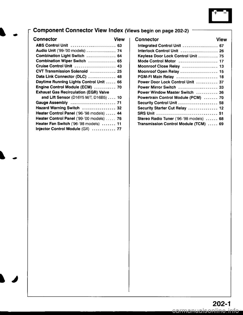
-
Component Connector View Index (Views begin on page 202-21
Connector View
ABS Control Unit........ ......63
Audio Unit ('99-'00 models) ......74
Combination Light Switch . . . . . . . . . . . . . . . 64
Combination Wiper Switch . . . . . . . . . . . . . . 65
Cruise Control Unit.... .....43
C\TTTransmission Solenoid ............. 25
Data Link Connector (DLC) ..... 48
Daytime Runnlng Lights Control Unit ..... 66
Engine control Module (ECM) ...........70
Exhaust Gas Recirculation (EGR) Valve
and Lift Sensor (D16Y5 Mfl, D1685) . . . . 10
Gauge Assembly .............71
HazardWarnlngSwitch,,. .,,,...,,,,... 32
Heater Control Panel ('96-'98 models) .....44
Heater Control Panel ('99-'00 models) ...., 76
Heater Fan Switch ('96-'98 models) ,,,.... 11
fniector Control Module (GX) ............77
I/
202-1
Connector View
Integrated Control Unit .......,. 67
f nterfock Control Unit .... ...... 26
Keyfess Door Lock Control Unit . . . . , . . . . . 75
Mode Control Motor ... ........'17
Moonroof Close Relay .. .......13
Moonroof Open Relay ... .......15
PGM-FI Main Relay .. .......... 18
Power Door Lock Conlrol Unil ..... ...... 37
Power Mirror Switch .,... ...... 33
Power Window Master Switch .,.........36
Powertrain Control Module (PCM) .......70
Security Control Unit ..., ..,,... 58
Security Starter Cut Belay ... ...,,,....,, 12
SRS Unit ............. 51
Stereo Radio Tuner ('96-'98 models) ...... 68
Transmission Control Module CICM) .....69