Page 1304 of 2189
Front Seat
Removal
CAUTION: When prying with a flat-tip screwdriver, wrapit with protective tape lo prevent damage.
NOTE: Take care not to scratch the seat covers and body.
1. Remove the seat track end cover, then remove thebolts.
SEAT TRACKCOVER
FRONT SEAT
)
SEAT TRACKEND COVER
BOLT8 x'1.25 mft22 N..n 12.2 kgl.m,16 rbf.ft)
8 x 1.25 mm22 N.rn 12,2 kgl.m,16 tbtft)
20-74
2. Lift the driver's front seat, then disconnect the seatbelt switch connector.
SEAT BELTswtTcHCONNECTOR
4.
Remove the headrest.
Carefully remove the front seat through the dooropening.
Installation is the reverse ol the removal procedure.
NOTE: Make sure the connector is connected prop-
erry.
5.
Page 1331 of 2189
Hatch Spoiler
Removal
NOTE: Take care not to scratch the hatch and body
1. Remove the hatch upper trim (see page 20-63)
2. Remove the nuts, and detach the clip, then lift the
hatch spoiler uP.
a: Nut locations, 4
1 2lbt.ftl _ j/
GROMMET
HIGH MOUNT BRAKELIGHT CONNECTOR
Disconnect the high mount brake light connector and
rear window washer tube, then remove the hatch
spoiler.
------,*;)
4. lf necessary. remove the spoiler trim from the spoiler
frame.
NOTE: The hatch spoiler trim for Canada produced
cars cannot be disassembled.
>: Clip locations
A>,4
>: Scr€w
5. Installation is the reverse of the removal procedure'
NOTEi
. lf necessary, replace any damaged clips.
a Make sure the connector and washer tube are
connected ProPerlY.
20-101
Page 1468 of 2189

Condenser
Replacement
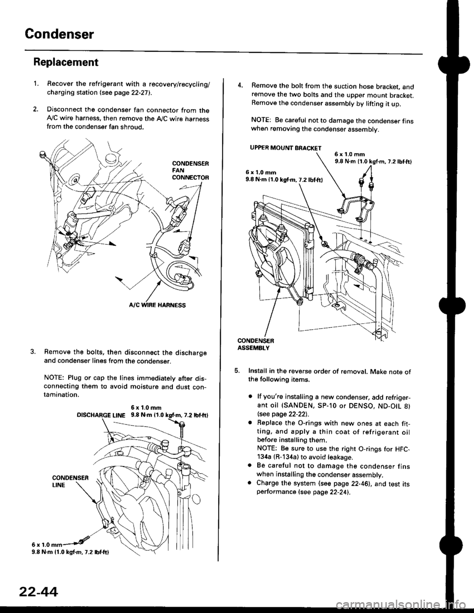
1.Recover the refrigerant with a recovery/recycling/
charging station lsee page 22-271.
Disconnect the condenser fan connector from theAy'C wire harness, then remove the A,/C wire harnessfrom the condenser fan shroud.
Remove the bolts, then disconnect the dischargeand condenser lines from the condenser.
NOTE: Plug or cap the lines immediately after dis-connecting them to avoid moisture and dust con-tamination,
6r1.0
6x1.0mmolscHARGE L|NE 9.8 N.m 11.0
9.8 N.m 11.0 kgl.m, 7.2 lbf.ftl
22-44
4. Remove the bolt from the suction hose bracket, andremove the two bolts and the upper mount bracket.Remove the condenser assembly by lifting it up.
NOTE: Be careful not to damage the condenser finswhen removing the condenser assembly.
UPPER MOUNT BRACKET
5. Install in the reverse order of removal. Make note ofthe following items.
. lf you're installing a new condenser, add refriger-ant oil (SANDEN, SP-10 or DENSO, ND-O|L 8)
\see page 22-22l.-
. Replace the O-rings with new ones at each fit-ting, and apply a thin coat of refrigerant oilbefo.e installing them.
NOTE; Be sure to use the right O-rings for HFC,134a (R-134a) to avoid leakage.o Be careful not to damage the condenser finswhen installing the condenser assembly.. Charge the system (see page 22-46), and test itsperformance (see page 22-24i.
6x1.0mm9,8 N.m 11.0 kg{.m, 7.2lbtft}
6x1.0mm9.8 N.m 11.0 kst m, 7.2 lbf.ftl
Page 1569 of 2189

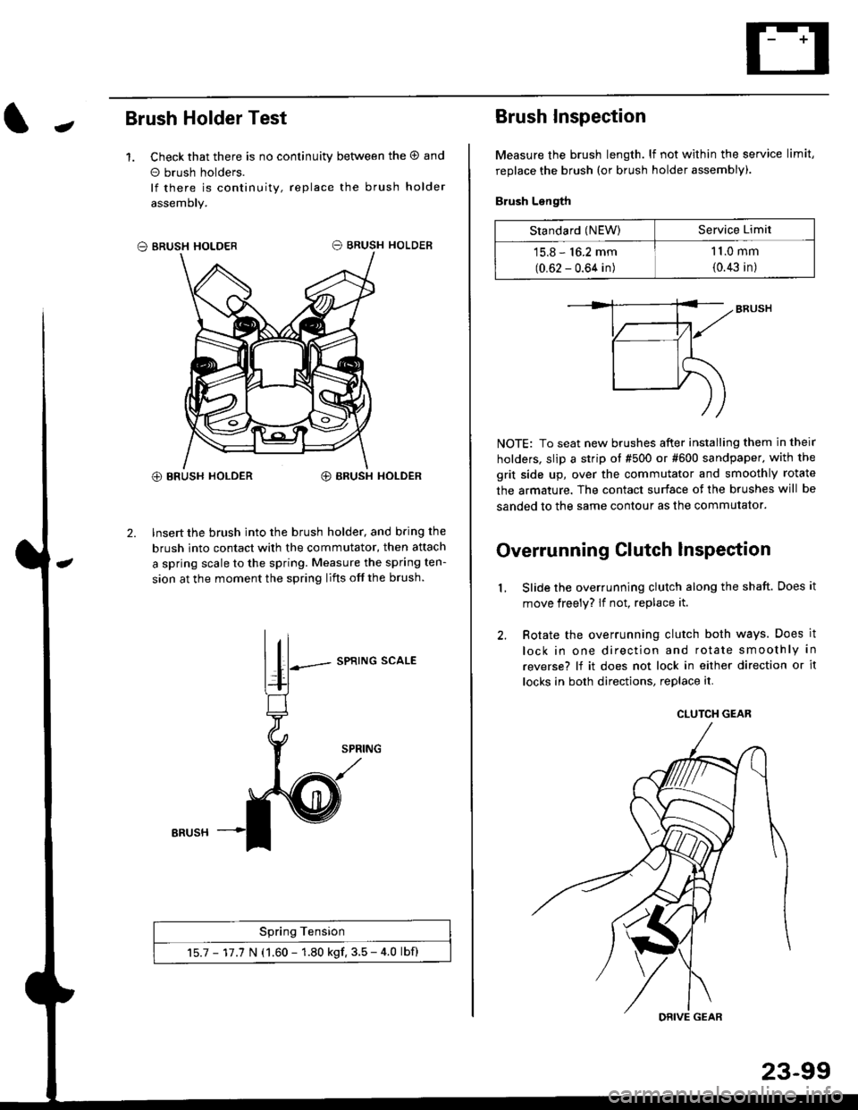
JBrush Holder Test
1. Check that there is no continuity between the O and
o brush holders.
lf there is continuity, replace the brush holder
assemoly.
O BRUSH HOLDER
@ BRUSH HOLDER€) BRUSH HOLDER
2. Insert the brush into the brush holder, and b.ing the
brush into contact with the commutator, then attach
a spring scale to the spring. Measure the spring ten-
sion at the moment the spring lifts off the brush.
SPRING SCALE
Spring Tension
15.7 - 17.7 N (1.60 - 1.80 kgf. 3.5 - 4.0 lbf)
ERUSH
Brush Inspection
Measure the brush length. lf not within the service limit,
replace the brush (or brush holder assembly).
Brush Length
NOTE: To seat new brushes after installing them in their
holders, slip a strip ot #500 or #600 sandpaper. with the
grit side up, over the commutator and smoothly rotate
the armature. The contact surface of the brushes will be
sanded to the same contour as the commutator.
Overrunning Clutch lnspection
Slide the overrunning clutch along the shaft. Does it
move freely? lf not, replace it.
Rotate the overrunning clutch both ways. Does it
lock in one direction and rotate smoothly in
reverse? lf it does not lock in either direction or it
locks in both directions, replace it.
2.
L
Standard (NEW)Service Limit
15.8 - 16.2 mm
(0.62 - 0.64 in)
1 1.0 mm
{0.43 in)
CLUTCH GEAR
DRIVE GEAR
Page 1806 of 2189
Airbag
Replacement (cont'd)
Front Passenger's Side:
. Remove the three mounting nuts from the bracket,then remove the harngss clip.. Lift the front passenger's airbag out of the dashboardby covering the lid and dashboard with a cloth, andprying carefully with a flat-tip screwdflver.
NOTE: The lid of the airbag has pawls on its sidewhich attach it to the dashboard.
24-6a
CAUTION: B€ sure to inslall the SRS wiring so that it isnot pinched or interforirg with other parts.
4. Installthe new airbag(s):
Driver's Side: Place the driver,s airbag into the steeringwheel, and secure it with new Torx botrs.
TORX BOLTS9.E N.m (1,0 kgf.m, 7.2 tbt ftlReplace.
Front Pass€ngar's Side:
. Place the front passenger,s airbag into the dash-board.
. Tighten the front passenger,s airbag mounting nuts.
ANAAG MOUNTING NUTS9.8 N.m 11.0 kgf.m, 7.2lbf.frlReplace.
DRIVER'S AIRBAG
Page 1840 of 2189

Ground-to-Components I ndex
f.,lONOTE: All ground wires are BLK unless otherwise noted.
GroundPageComponents or Circuit Grounded
Battery (BLKYEL)
Steering pump bracket
t+-rg ITransmission housing
l
G101
(-1)
G101
(-2)
14-2
and
14-3
ano
14-1
Powertrain or engine control module (PG1 and pG2 are BLK: LG1 and LG2 are
BRN/BLK), EGR control solenoid valve (CW, EGR valve and lift sensor (Dt6yS enginewith M,/T), Engine coolant temperature switch, pGM-Fl main relay, power steeringpressure switch (USA), Primary HO2S (D16Y5 engine with l\/,/T), Vehicle speed sensor,VTEC pressure switch (D16Y5/D16Y8 engines), CKF sensor (BRN/BLK), Transmission
control module (CYf) (Pc1 is BLK: LG1 is BRN/BLK)
Shielding betvveen the PCM or ECM and these components (all have BRN/BLK wires):
CKF sensor, TDC/CKP/CYP sensor. Primary and secondary heated oxygen sensors.
Knock sensor (CWDl6YB engine), Mainshaft speed sensor (AiT except CVT),
I Countershaft speed sensor (A/T except CVf)
Shielding between the TCM and these components (CVT) (all have BRN/BLK wires):
Drive pulley speed sensor, Driven pulley speed sensor, Secondary gear shaft
speed sensor
Powertrain or engine control module (PG1 and pG2 are BLK; LG1 and LGz are
BRN/BLK), EGR control solenoid valve (D16Y5 engine), EGR valve (Dt685), Engine
coolant temperature switch, Fuel pressure regulator shut-off solenoid valve (D1685),
PGM-FI main relay, Power steering pressure switch (USA), Vehicle speed sensor, VTECpressure switch (All except D16Y7 engine), CKF sensor (A
except 81642) (BRN/BLK)
Shielding between the PCM or ECM and these components (all have BRN/BLK wires):
CKF sensor, TDC/CKP/CYP sensor, Primary and secondary heated oxygen sensors,
Knock sensor (All except D16Y7 engine), i/ainshaft speed sensor (Arf except CW),
Countershaft speed sensor (A,/T except CVf), Drive pulley speed sensor (CW), Drivenpulley speed sensor (CVT), Secondary gear shaft speed sensor (CVf)
I Badiator fan motor, Right front parking/turn signat tight, Right headtight
G20214-4I Cruise control actuator, Left front parking/turn signal lights, Left headlight, Rear window
I washer motor, Windshield washer motor, Washer fluid level switch (,99-'00 Canada)
G401| +-o
and
14-7
Accessory power socket, Brake fluid level switch, Clutch interlock switch (M/T), Clutchswitch (lillT with cruise/D16Y5 engine with MfD, Combination wiper switch (Z wires),
Cruise control main switch, Cruise control unit, Dash lights brightness controller, Data
link connector, Daytime running lights control unit (Canada), Gauge assembly, Horn('96-'97 models), Integrated control unit, Interlock control unit (ArI), Keyless door lock
control unit ('99-'00 models with keyless), Moonroof close and open relays, Moonroof
switch, Park pin switch (A/r), Power window relay, Rear window defogger relay, Rear
window defogger switch ('96-'98 models), Steering lock, Stereo radio tuner (,96-,98
USA: LX, EX, and HX), Turn signal/hazard relay, Windshield wiper motor.....plus
everything grounded through G402
6-6
Page 1901 of 2189
I -.. t
iecnuaruerirt Rererence rp iiftii* l"*o, $'n"o.
t
.i sensor Input voltaqe sensor input inpul input inp"r II TEGFL' rvca?r Opsl rFirir.rxt rECn i,ari tL------- _______.J
PGM-FI (All '99-'00 Models except D16Y5 with M/T and D16B5) (cont,d)
- D16Y5 Engine
BLK
c131PHOTOssvtEW 59
ENGINECOOLANTTEMPER.ATURE(ECr)SENSORPBO|A 32
c130Oerminals 18-20)
vtEW 52
YEUALU
20
YEUALU
YEUALU
YEUBLU
1
YEUBLU
ALU
LT GFN
EXHAUST GASRECIRCULATION(EGR) VALVELIFT SENSORPHO|O 36
TEMPER.
tllfrtr'l
I J tffiT,.:'
""",:I
1r:{
Slt or
lr;: H
H#*iiff''I
fi[ffi,''""."'.1
"_
[;,l;,+. N
:{I
c1t5(ferminals 8-14)
vtEw38
n"","*[
"raI
r -,^^:.I POWERTRAIN| "ji""il, I corrnor
lu'"t !H"3fii:'L __ J V|EW 7a
24-6
Page 1913 of 2189
PGM-FI (D1685) (cont'd)
EGRvdvo Fuer ia ( tEGR In pres$uro \valvs s€mor nd*6nc6 lP i.snsor h.tsl lank tenF, Icont ol inDut volt|ce s8fi8of inDul inbut ssnsof ifix, I: control inDln voltac€ s€{tlor input inout sonsol ingJl ;I G.€GF} GGf,q N@a fiPg' .(PFoJ fiFO) ,L------- ------J
j
c2887
c150PHOTO 112
C'ro1PHO|O sl
c575
vtEw 7i
(FUELTA}IKTEMPEB.ATURESENSOR
H1Y
FUEL TANKPRESSURESENSOnPHOTO 116
THROTTLEPOSrT|0NCIP)SENSOR
EXHAUSTGAS RECIR.CULATION(EGR) VALVEand LIFTSENSORPHOfO 36
"""r":x
o
GRI{/BLK
4
GNN/BLK
GNN/gLK
c575
c401PHOfO 57vtEw 40
2
GRN/BL(
cls0
a
POWERTBAINCONTROLMOOULE(PCM)PHOfO 86
I
I
IJ
n"*r"a^[
'rcai/BLX llcre Ar--?
lsJiH,
I ground
I
25-6