Page 1039 of 2189

Driveshafts
Disassembly (cont'dl
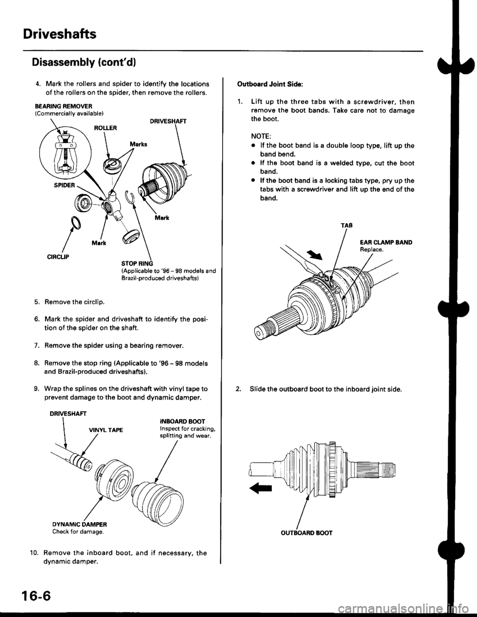
4. Mark the rollers and spider to identify the locations
of the rollers on the sDider, then remove the rollers.
B€ARING REMOVER{Commerciallv available}
STOP RING(Applicable to '96 - 98 modols andErazil-produced driveshafts)
Remove the circlip.
Mark the spider and driveshaft to identify the posi-
tion ot the spider on the shaft.
Remove the spider using a bearing remover.
Remove the stop ring (Applicable to '96 - 98 models
and Brazil-produced driveshafts).
Wrap the splines on the drivsshaft with vinyl tape to
prevent damage to the boot and dynamic damper.
DRIVESHAFT
1.
VINYL TAPE
DYNAMIC DAMPERCheck for damage.
Remove the inboard
dynamic damper.
INBOARO AOOTInspect for cracking,splitting and wear.
16-6
boot, and if necessary, the
Outboard Joint Side:
1. Lift up thc three tabs with a screwdriver, then
remove the boot bands, Take care not to damage
the boot.
NOTE:
. lf the boot band is a double loop type, lift up the
band bend.
. lf the boot band is a welded type, cut the boot
band.
. lfthe boot band is a locking tabs type, pry up the
tabs with a scr€wdriv€r and lift uo the snd of the
band.
2. Slide the outboard boot to the inboard ioint side.
TAB
OUTBOABD BOOT
Page 1046 of 2189
l.
11. Set the double loop band onto the boot and dynam-
ic damper with the band end toward the front ot the
vehicle.
LOOP BANO
Pull up the slack in the band bY hand
Mark a position on the band 10 - 14 mm {0 4 - 0 6
in) from the cliP.
DOUBLE
,
1')
13.
CLIP
Ip
14.
15.
Thread the free end of the band through the nose
section of the boot band tool and into the slot on
the winding mandrel.
Place a wrench on the winding mandrel of the boot
band tool, and tighten the band until the mark you
made on the band meets the edge of the clip.
Mark on band.
Lift up the boot band tool to bend the free end
the band 90 degrees, then center-punch the clip'16.
(cont'd)
16-13
(KD-3191 or equivalent)
HAMMER
Page 1050 of 2189
I
13. Fit the boot ends onto the driveshaft and the
outboard joint
Fit the double loop boot bands onto the boot ends'
Pull up the slack in the band by hand'
Mark a position on the band 10 - 14 mm {0 4 - 0 6
in,) from the cliP.
14.
16.
CLIP
lrz
17. Thread the free end of the band through the nose
section of a commercially avaiiable boot band tool
KD-3191 or equivalent and into the slot on the wind-
ing mandrel.
BOOT BAND TOOL
lCommerciallY available)
KD-3191 or equivalent
MANDREL
Place a wrench on the winding mandrel of the boot
band tool, and tighten the band until the marked
spot on the band meets the edge of the clip'
Lift uo the boot band tool to bend the free end of
the band 90" to the clip Center punch the clip, then
fold over the remaining tail onto the clip
Mark spot.
18.
1q
(cont'd)
16-17
Page 1144 of 2189
Front Damper
Installation (cont'd)
2. Install the damper fork over the driveshaft and onto
the lower arm. Install the front damper into the
damper fork so the aligning tab is aligned with the
slot in the damper fork.
ALIGNING TAB
DAMPERPINCHEOLT10 x 1.25 mm43 N.m 14.4 kgf.m, 32 lbtftl12 x 1.25 mm64 N.m 16.5 kgl.m, 47 lbtftlReplace.
Loosely install the damper pinch bolt into the top ofthe damper fork.
Loosely install the damper fork bolt and a new self-locking nut into the bottom of the damper fork.
Raise the knuckle with a floor jack until the vehiclejust lifts off the safety stand.
@E The ftoor ilck must be sscuroty posi-
lionsd or personal iniury may r€€uh.
Tighten the damper pinch bolt.
Tighten the damper fork bolt and self-locking nut.
Tighten the flange nuts on top of the damper.
Install the brake hose mounts with the brake hose
mounting bolts.
Install the front wheel.
7.
8.
9.
10.
1a-20
Page 1153 of 2189
Rear Damper
Ilnstallation
'1. Lower the rear suspension, and position the
damper with the spring stop pointed toward the left
SPRING STOP
2. Loosely installthe two flange nuts
FLANGE NUTS10 x 1.25 mm49 N.m (5 kgf.m, 36 lbt'ft)
Tighten these nuts in
step 7.
lr
3. Loosely install the flange bolts.
FLANGE BOLT10 x 1.25 mm54 N.m {5.5 kgf m, 40 lbt'ft1
FLANGE BOLT10 x 1 .25 mm54 N.m {5.5 kgf.m,/r0 lb{.ft|
7.
Raise the rear suspension with a floor jack until the
vehicle just lifts off the safety stand.
!@@ Tne floor iacx must be securelY Posi-
tionod or peFonal iniury may rssull
Tighten the flange bolts.
Tighten the two flange nuts on top of the damper to
the specified torque.
Check the rear wheel alignment and adjust if neces-
sary (see page 18-4).
1A-29
Page 1282 of 2189
Moonroof
Glass, Glass Bracket and Sunshade Replacement
l. Close the glass fully.
2. Slide the sunshade all the way back.
3. Remove both bracket covers.
Forward_--____->
4. Remove the nuts from both glass brackets.
6x1.0mm9.8 N.m (1.0 kgf.m,7.2lbt.ftl
Remove the glass by lifting up and pulling forward
as shown.
NOTE: Do not damage the roof panet.
ERACKET COVER
GLASS EBACKET
GLASS
\
20-52
DRAIN CHANNEL
6. Remove the drain channel.
7. Remove the holder cover. then remove the
holder B.
NUT6x1.0mm9 N.m {0.9 kgf.m.? tbtftl{i;t'm
RAIL HOLDER B
Using the moonroof wrench, move the glass bracket
to the position where the moonroof normally pivots
down, and remove the screws.
scREws
Page 1285 of 2189

L
L
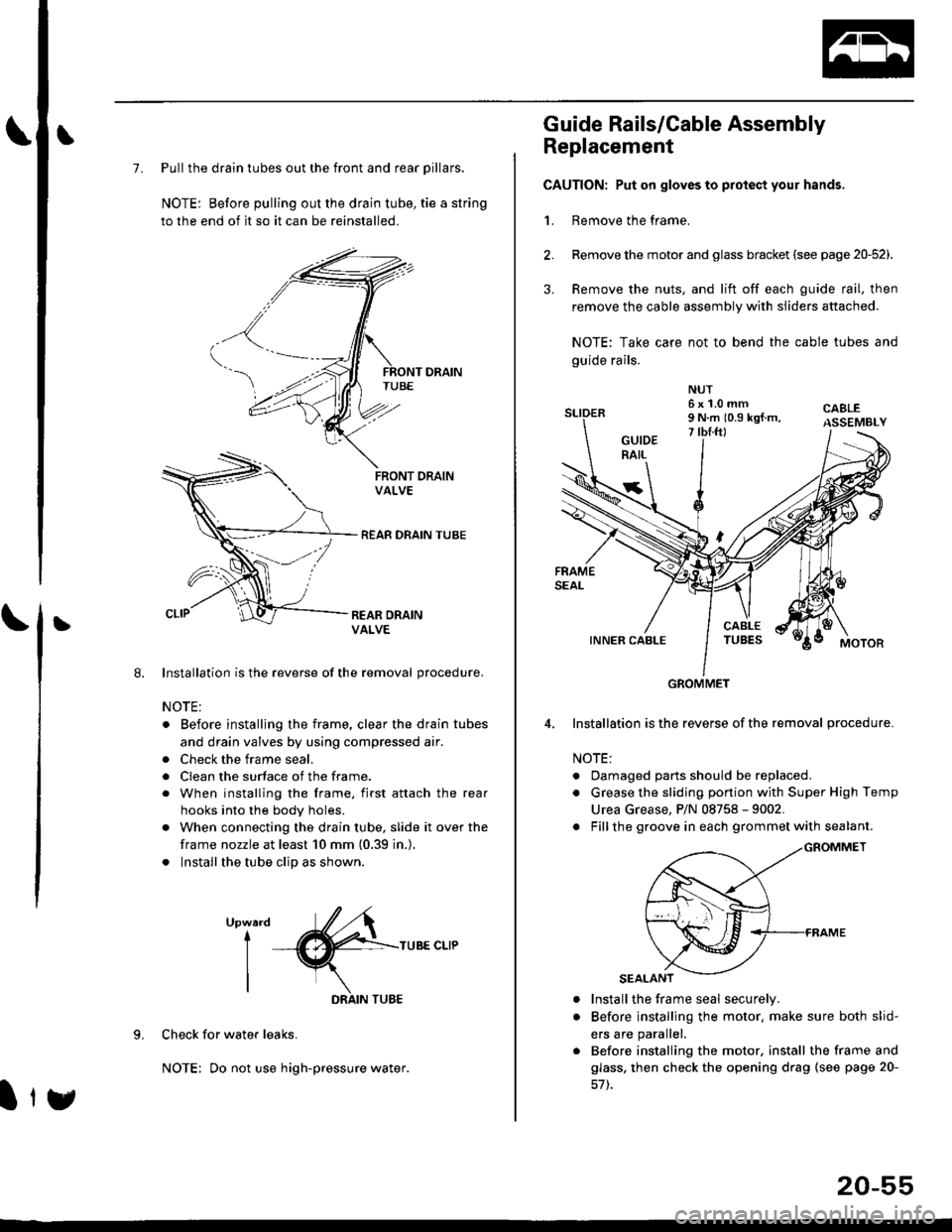
7. Pull the drain tubes out the front and rear pillars.
NOTE: Before pulling out the drain tube, tie a string
to the end of it so it can be reinstalled.
Installation is the reverse of the removal procedure.
NOTE:
. Before installjng the frame, clear the drain tubes
and drain valves by using compressed air.
. Check the frame seal.
. Clean the surface of the frame.
. When installing the frame, first attach the rear
hooks into the body holes.
. When connecting the drain tube, slide it over the
frame nozzle at least 10 mm (0.39 in.).
. Install the tube clip as shown.
UpwardI
I
I
TUBE CLIP
Check for water leaks.
NOTE: Do not use high-pressure water.
DRAIN TUBE
Ity
20-55
Guide Rails/Cable Assembly
Replacement
CAUTION: Put on gloves to protect your hands,
1. Remove the frame.
Remove the motor and glass bracket (see page 20-52).
Remove the nuts, and lift off each guide rail, then
remove the cable assembly with sliders attached.
NOTE: Take care not to bend the cable tubes and
guide rails.
Installation is the reverse of the removal procedure.
NOTE:
. Oamaged parts should be replaced.
. Grease the sliding portion with Super High Temp
Urea Grease, P/N 08758 - 9002.
. Fillthe groove in each grommet with sealant.
a
a
Install the frame seal securely.
Before installing the motor. make sure both slid-
ers are parallel.
Before installing the motor. install the frame and
glass, then check the opening drag (see page 20-
GROMMET
Page 1301 of 2189
Remove the following parts Irom the dashboard'
. Driver's dashboard side cover
o Passenger's dashboard lower cover
. Dashboard center lid
Disconnect the connectors and air mix control cable'
6x1.0mm9.8 N.m 11.0 kgl.m,
D>, 1
@7 2'orftl - ---//_._J
,{nil Lll , ,"o
Ift#5 L //Hl Wlj%u|5 i//Wt qT
W72-t11 7'::--J
>: Clip locationsA>, 1 B>, 1
Loosen the bolt.
DASHBOARD
AIR MIX CONTROL
CONNECTORS
FRONT PASSENGER'SAIRBAG CONNECTOR
Remove the bolts, then lift and remove the dashboard'
CAUTION: Use proteqtive plates on the bottom ot the front pillar trim'(cont'd)
20-71
M,::;:"lx3T:iJnif:3lilH:fl"*:1::f"*'il;ili"'"
disconnect rhe front passeneer's airbas
>: Bolt, screw locaiions
A>,7B>, 1
,i( 8x125mm(!,@ 22 N.m t2.2 kstm,-v, 16 tbf.ftl
8xl.25mm I22 N.m 12.2 kgt'm, I'"tt:___J
c>, 1
@
c>,6