1998 HONDA CIVIC Hoses
[x] Cancel search: HosesPage 1171 of 2189
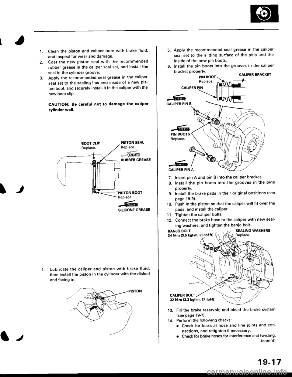
'1.Clean the piston and caliper bore with brake fluid,
and inspect for wear and damage.
Coat the new piston seal with the recommended
rubber grease in the caliper seal set. and install the
seal in the cylinder groove.
Apply the recommended seal grease in the caliper
seal set to the sealing lips and inside of a new pis-
ton boot, and securely install it in the caliper with the
new boot clip.
CAUTION: Be careful nol to damage the caliper
cylinder wall.
PISTON SEALReplace.
--^.,:=-qE!!!-HRUBBER GREASE
Lubricate the caliper and piston with brake fluid,
then install the piston in the cylinder with the dished
end facing in.
IJPISYON BOOTReplace.
j@i
SILICONE GREASE
CALIPER
-6lCALIPEB PIN B
Apply the recommended seal grease in the caliper
seal set to the sliding surface of the pins and the
lnside of the new pin boots.
lnstall the pin boots into the grooves in the caliper
bracket properly.CALIPER ERACKET
7. Insert pin A and pin B into the caliper bracket.
8. Install the pin boots into the grooves in the pans
propeny.
9. Install the brake pads in their original positions (see
page 19-9).
10. Push in the piston so that the caliper will fit over the
pads, and install the caliPer.
11. Tighten the caliper bolts.
12. Connect the brake hose to the caliper with new seal-
ing washers, and tighten the banjo bolt.
-6.lPIN BOOTSReplace.
-6lCALIPER PIN
BANJO EOLT34 N.m (3.5 kg{ m, 25 lbflt}SEALING WASHERSReplace.
'13.
CALIPER BOLT32 N.m 13.3 kgt.rn, 24lblft)
Fill the brake reservoit and bleed the brake system
{see page 19-7).
Perform the following checks:
. Check for leaks at hose and line joints and con-
nections. and retighten if necessary.
. Check for brake hoses for interference and twisting.(cont'd)
14.
19-17
Page 1174 of 2189
Front Brake Caliper
Reassembly (cont'dl
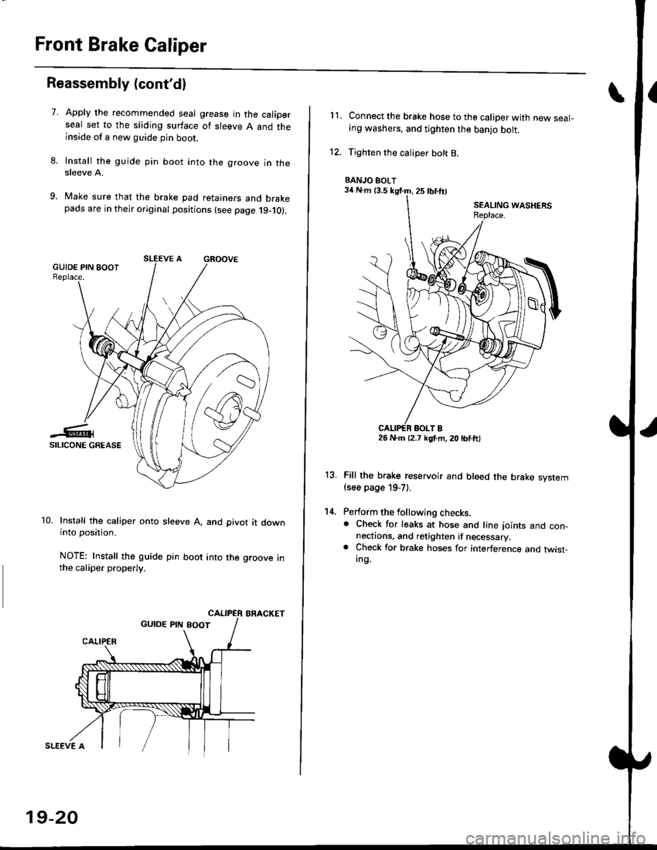
7.Apply the recommended seal grease in the caliperseal set to the sliding surface of sleeve A and theinside of a new guide pin boot.
Install the guide pin boot into the groove in thesleeve A.
Make sure that the brake pad retainers and brakepads are in their original positions (see page 19-10).
Install the caliper onto sleeve A, and pivot it downinto position.
NOTE: Install the guide pin boot into the groove inthe caliper properly.
BRACKET
SLEEVE A
19-20
11.Connect the brake hose to the caliper with new seal-ing washers, and tighten the banjo bolt.
Tighten the caliper bolt B.
Fill the brake reservoir and bleed the brake svstem(see page 19-7).
Perform the following checks.. Check for leaks at hose and line ioints and con-nectaons, and retighten if necessary.. Check for brake hoses for interference and twist-Ing.
13.
14.
BANJO BOLT
26 N.m (2.7 kgl.m, 20 lbtftl
Page 1178 of 2189
Rear Brake Pads
Inspection and Replacement
Never use an air hose or dry brush to clean brakeassemblies.
Use an OsHA-apptoved vacuum cl€aner to avoidbreathing brake dust,
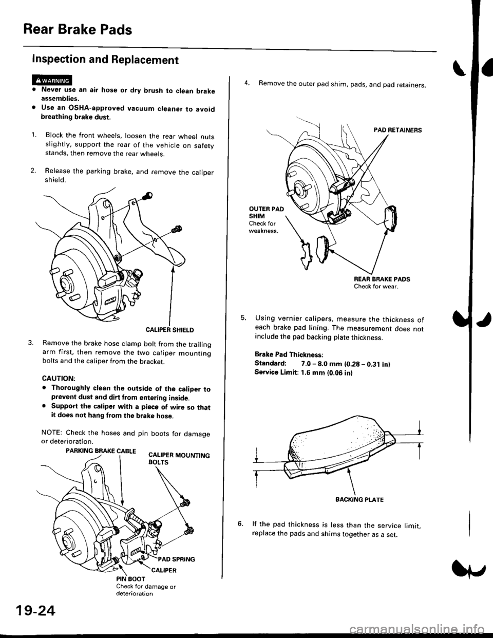
Block the front wheels, loosen the rear wneet nutsslightly, support the rear of the vehicle on safetystands, then remove the rear wheels.
Release the parking brake, and remove the calioersh ield.
CALIPER SHIELD
Remove the brake hose clamp bolt from the trailingarm first, then remove the two caliper mountingbolts and the caliper from the bracket.
CAUTION:
. Thoroughly clean the outside of the caliDer toprevent dust and dirt trom entering inside.. Support the calipor with a pieco of wire so thatit does not hang fuom the brake hose.
NOTEr Check the hoses and pin boots for damageor deterioration.
PARKING BRAKE CABLE ^.. ._-_ ---.
'L
19-24
4. Remove the outer pad shim, pads, and pad retainers.
PAO RETAINERS
OUTER PAOSHIMCheck for
REAR BRAKE PADSCheck for wear.
Using vernier calipers, measure the thickness ofeach brake pad lining. The measurement does notanclude the pad backing plate thickness.
Brake Pad Thickness:
Standard: 7.0 - 8.0 mm {0.28 - 0.31 in}Service Limit: 1.5 mm {0.06 in}
lf the pad thickness is less than the service limit,replace the pads and shims together as a set.
BACKING PI-ATE
Page 1193 of 2189
Brake Hoses/Lines
LJ
Inspection/Torque Specifications
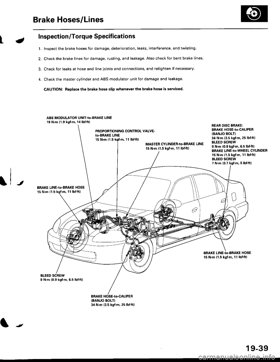
t. Inspect the brake hoses for damage, deterioration, leaks, interference, and twisting.
2. Check the brake lines for damage, rusting. and leakage. Also check for bent brake lines.
3. Check for ieaks at hose and line ioints and connections, and retighten if necessary'
4. Check the master cylinder and ABS modulator unit for damage and leakage
CAUTION: Replace tho brake hose clip whenev€r the brake hose is serviced.
ABS MODULATOR UNIT-Io-BRAKE l-lNE19 N.m (1.9 kgf.m, 14lbl.ftl
PROPOBTIONING CONTROL VALVE.io-BRAKE LINEl5 N.m (1.511 tbf.ftl
MASTER CYLINDER-Io-BMKE LINE
15 N.m (1.5 ksrf.m, 11 lbf'ft)
REAR DISG BRAKE:BRAKE HOSE-to4ALlPER
{BANJO BOLT}34 N.m (3.5 kgtm,25 lbf ftlBLEEO SCREW9 N'm (0.9 kgf.m, 6.5 lM.ftlBRAKE LINE-to-WHEEL CYLINDER15 N.m (1.5 kgl.m, 11 lbf.ftlBLEED SCREW7 N.m {0.7 kst m, 5 lbf,ttl
JBRAKE LINE-io-aRAKE HOSE15 N.m {1.511 tbtft)
BRAKE LINE-Io-BRAKE HOSE15 N.m (1.5 kgt.m, 11 lbf'ft)
(BANJO BOLT}3,1 N.m 13.5 kgf.m, 25 lbf.ft)
J
19-39
Page 1194 of 2189
Brake Hoses/Lines
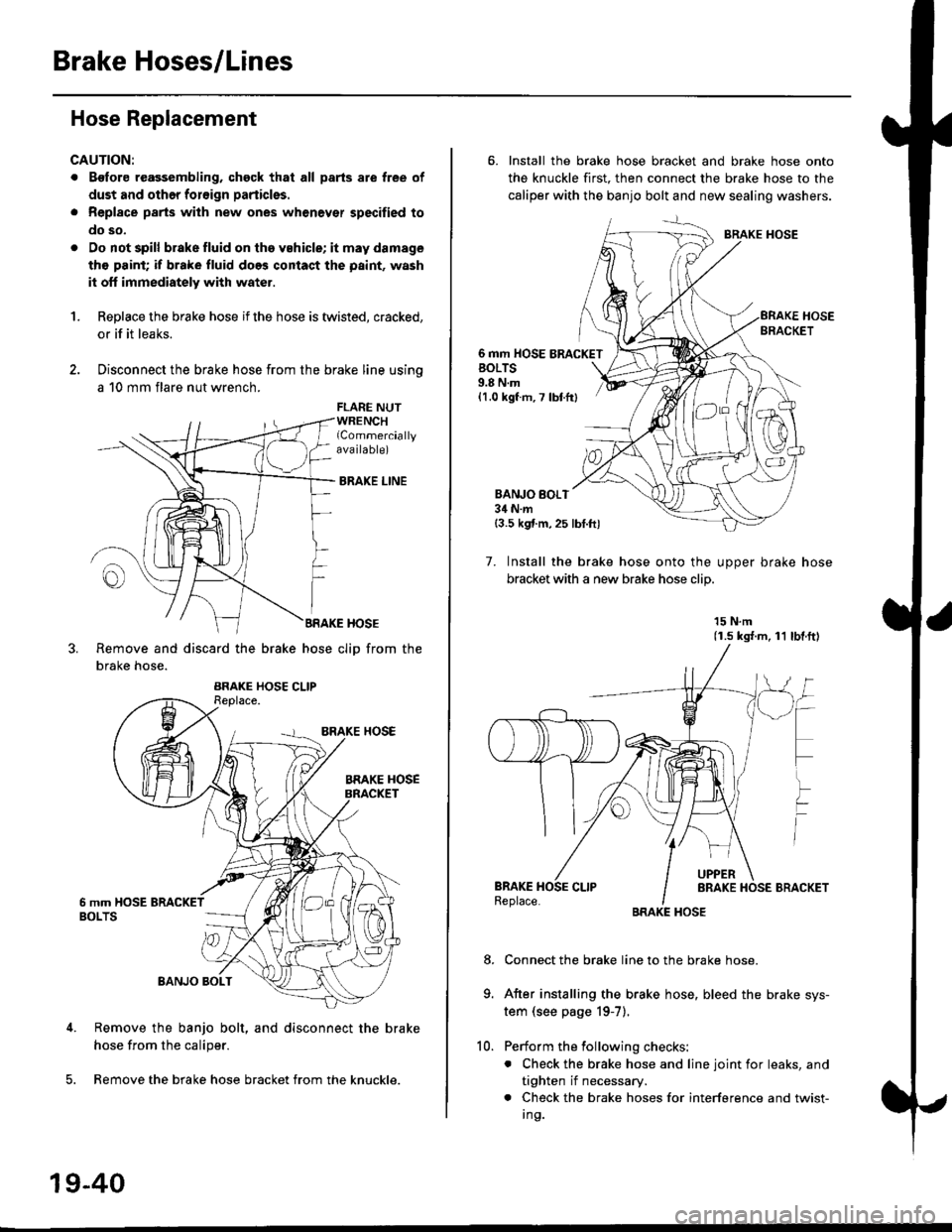
Hose Replacement
CAUTION:
. Bgfore reagsembling, chgck that all parts are free of
dust and othor foroign particles.
. Repl8ce parts with new ones whenever specified to
do so,
. Do not spill brake fluid on th6 vehicle; it may damage
tho paint; if brake fluid does contact the paint, wash
it off immediately with water.
1.Replace the brake hose if the hose is twisted, cracked,
or if it leaks.
Disconnect the brake hose from the brake line using
a 10 mm flare nut wrench.
FLARE NUTWRENCHlCommerciallyava ilable)
BRAKE LINE
BRAKE HOSE
Remove and discard the brake hose cliD from the
brake hose.
Remove the banjo bolt, and disconnect the brake
hose from the caliper.
Remove the brake hose bracket from the knuckle.
19-40
10.
6. Install the brake hose bracket and brake hose onto
the knuckle first. then connect the brake hose to the
caliper with the banjo bolt and new sealing washers.
BRAKE HOSE
6 mm HOSE BRACKETBOLTS9.8 N.m{1.0 kgf m, 7 lbtfr}
BANJO BOI.T34 N.m{3.5 kgf.m,25 lbt.ftl
7. Install the brake hose onto the uooer brake hose
bracket with a new brake hose clip
15 N.m(1.s ks{.m, 11 lbl.ftl
Connect the brake line to the brake hose.
After installing the brake hose, bleed the brake sys-
tem (see page 19-7).
Perform the following checks:
. Check the brake hose and line joint for leaks, and
tighten if necessary.
. Check the brake hoses for interference and twist-
I ng.
8.
Page 1413 of 2189
Heater Unit
Replacement
SRS components are located in this area. Review the
SRS component locations, precautions, and procedures
in the SRS section {24} before performing repairs or ser-
L Disconnect the negative cable from the battery.
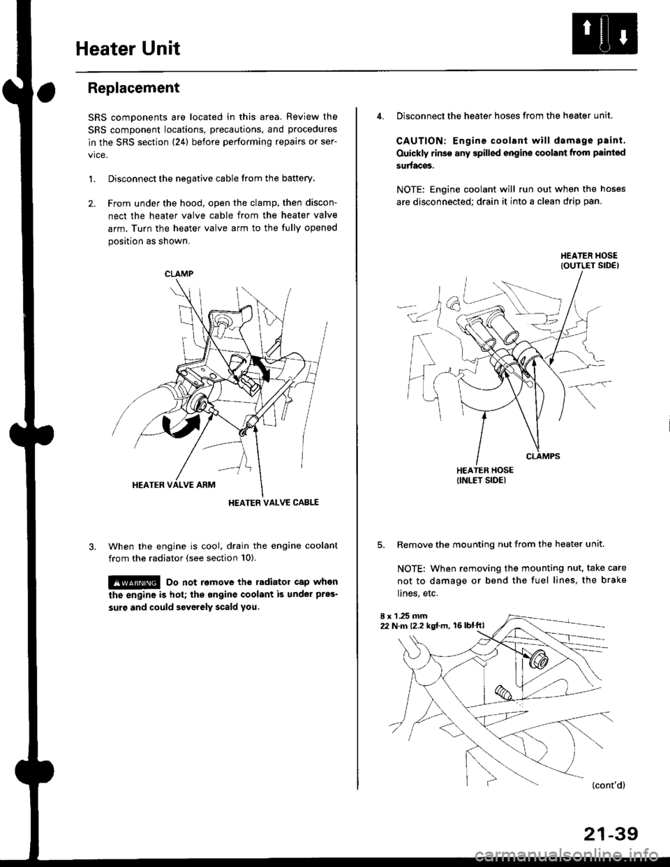
2. Frcm under the hood, open the clamp, then discon-
nect the heater valve cable from the heater valve
arm. Turn the heater valve arm to the fully opened
position as shown.
When the engine is cool. drain the engine coolant
from the radiator (see section 10).
!@ Do not remove the radiator cap when
the engine is hot; the ongine coolant is under pres'
surg and could severely scald you.
CLAMP
HEATER VALVC CABLE
4. Disconnect the heater hoses from the heater unit.
CAUTION: Engine coolant will damage p8int.
Ouickly rinse any spilled engins coolant from painted
su aces,
NOTE: Engine coolant will run out when the hoses
are disconnected; drain it into a clean drip pan.
5. Remove the mounting nut from the heater unit.
NOTE: When removing the mounting nut, take care
not to damage or bend the fuel lines, the brake
lines, etc.
I x 1 .25 mm22 N.m {2.2 kgl.m, 16lblftl
21-39
Page 1414 of 2189
Heater Unit
Replacement (cont'dl
6.
7.
8.
9.
Remove the dashboard (see section 20).
Remove the heater duct (see page 21-37) or evapo-
rator (see page 22-28).
Disconnect the connectors from the mode control
motor and air mix control motor ('99 - 00 models),
then remove the wire harness clips and wire har-
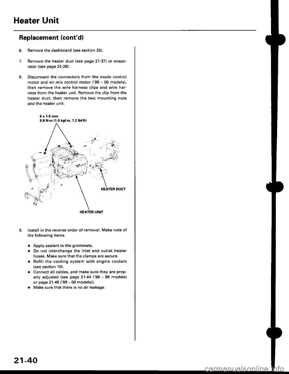
ness from the heater unit. Remove the clip from the
heater duct, then remove the two mounting nuts
and the heater unit.
6x1.0mm9.8 N.m 11.0 kgl.m,7.2 lbf.ftl
HEATER UNIT
lnstall in the reverse order of removal. Make note of
the following items.
Apply sealant to the grommets.
Do not interchange the inlet and outlet heater
hoses. Make sure that the clamps are secure.
Refill the cooling system with engine coolant
(see section 10).
Connect all cables, and make sure they are prop-
erly adjusted (see page 21-44 (96 - 98 models)
or page 21-45 ('99 - 00 models)).
Make sure that there is no air leakage.
21-40
Page 1470 of 2189
A/C System Service
Charging
Use only service equipment that is U.L.-listed and is cer-
tified to meet the requirements of SAE J2210 to remove
HFC-134a (R-134a) from the air conditioner system.
CAUTION: Exposure to air conditioner refrigerant and
lubricant vapor or mist can irritale eyes, nose and
throat. Avoid breathing the air conditioner retrigerant
and lubricant vaoor or mist,
lf accidental system discharge occurs, ventilate workarea before resuming service, Additional health and
safety information may be obtained from the refrigerant
and lubricant manufacturers.
Refrigerant capacityt 600 - 650 g 121.1 - 22.9 ozl
CAUnON: Do not overcharg€ the system; the comprcssor
will be damaged.
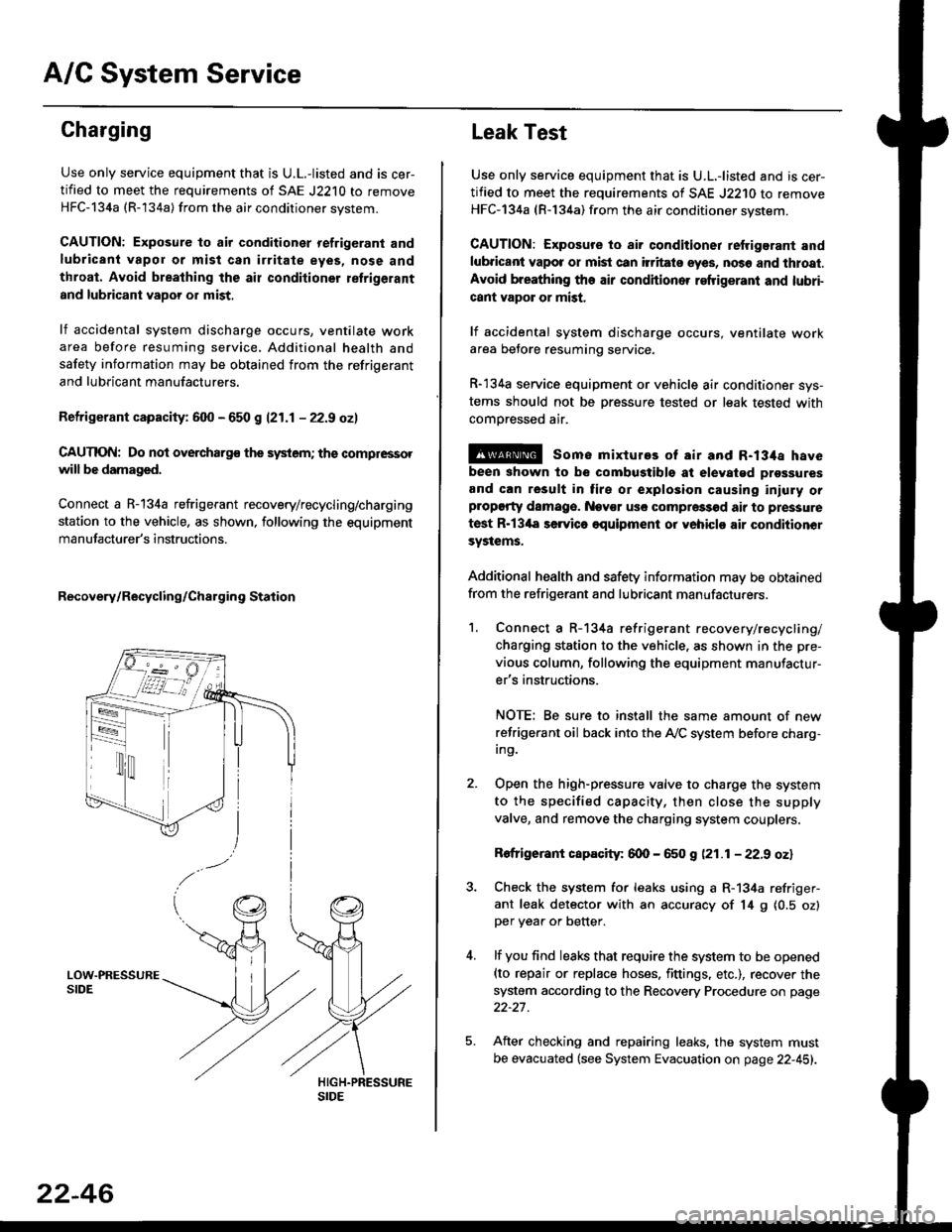
Connect a R-134a refrigerant recovery/recycling/charging
station to the vehicle, as shown, following the equipment
manufacturer's instructions.
Recovery/Recycling/Charging Station
22-46
Leak Test
Use only service equipment that is U.L,-listed and is cer-
tified to meet the requirements of SAE J2210 to remove
HFC-134a (R-134a) from the air conditioner system.
CAUTION: Exposure io air conditioner refrigerant and
lubricant vapot or mist can itritats eyes, no36 and thtoat.
Avoid breathing the air conditioner refrigeranl and lubri-
cant vapor or mist,
lf accidental system discharge occurs, ventilate workarea betore resuming service.
R-134a service equipment or vehicle air conditioner sys-
tems should not be pressure tested or leak tested with
comoressed air.
@ some mixtures of air and R-134a have
been shown to be combugtibls at elevatgd prossures
and can result in tire or explosion causing iniuly orplopgrty damage. Nev€r usc compre33od air to pressure
test R-13'la servica oquipment or yohiclo air conditionor
systems.
Additional health and safety information may be obtained
from the refrigerant and lubricant manufacturers.
1. Connect a R-134a refrigerant recove rylrecycling/
charging station to the vehicle, as shown in the pre-
vious column, following the equipment manufactur-
er's instructions.
NOTE; Be sure to install the same amount of new
refrigerant oil back into the A,/C system before charg-In9.
Open the high-pressure valve to charge the system
to the specified capacity, then close the supply
valve, and remove the charging system couplers.
Rofrigerant capacity: 600 - 650 g (21.1 - 22.9 oz)
Check the system for leaks using a R-134a refriger-
ant leak detector with an accuracy of 14 9 10.5 ozlper yea. or better.
lf you find leaks that require the system to be opened(to repair or replace hoses. fittings. etc.), recover the
system according to the Recovery Procedure on page
22-27.
After checking and repairing leaks. the system must
be evacuated (see System Evacuation on page 22-451.