1998 HONDA CIVIC Hoses
[x] Cancel search: HosesPage 870 of 2189

Shift Indicator PanelATF Cooler Hoses
Adiustment
'1.Check that the index mark on the indicator alionswith the N mark on the shift indicator panel whenthe transmission is in NEUTRAL.
3 N.m {0.3 kgf.m, 2lbt.ftl
lf not aligned. remove the front console {see section20t.
Remove the shift indicator panel mounting screwsand adjust by moving the panel,
NOTE: Whenever the shift indicator panel is removed,reinstallthe panel as described above,
INDEX MARK
L
14-192
Connection
1. Connect the ATF cooler hoses to the ATF cooler linesand ATF cooler, and secure them with the clips asshown.
TRANSMISSION CLIP
Page 871 of 2189

Continuously Variable Transmission (CVTI
Special Tools ................ 14-194
Description .................... 14-195
Clutches/Reverse Brake/Planetary
Gear/Pulleys .......... 14-198
power Flow ..............,..... 14-200
Electronic Control SYstem(,96 - 98 Modets) ......14-203
Electronic Control System
('99 - oo Models) " 14-205
Hydraulic Control '....... 14-208
Hydraulic Flow .'..-.....'... '14-212
Park Mechanism .....-...'.' 14-222
Eleqtrical Systom
Component Locations'96 - 98 Models """"""' 14-224,99 - 00 Modets ............. 14-225
TCM Circuit Diagram ('96 - 98 Models) ............. 14-226
TCM Terminal Voltage/Measuring Condiiions ('96 - 98 Models) '.... 14-228
PcM Circuit Oiaqram{A/T Control System: '99 - 00 Models} ...--.... 14-230
PCM Terminal Voltage/Measuring Conditions('99 - 00 Models)
A/4 Control System .'.'...14-232
Troubleshooting Procedures ... . .... .....',........."' '14-234
Symptom-to-ComPonent Chart
Electrical System - '96 - 98 Models ......'..... '14-234
Electrical System -'99 - 00 Models ..'....-..-. '11-210
Electrical Troubleshooting
Troubleshooting Flowcharts('96 - 98 Models) """'11-242
Troubleshooting Flowchart
('99 - 0O Modets) ...... 14-265
Linear Solenoids/lnhibitor Solenoid
Test ......................... . ...... 14-29f
Drive Pulley/Driven Pulley/Secondary Gear
Shaft Speed Sensors
Replacement .........'...... .14-292
Start Clutch Control
Start Clutch Calibration Procedure ....... ....,. 14-293
Hydraulic SYstem
Symptom-to-ComPonent Chart
Hydraulic System '.'.......14-294
Road Test ............................ 14-296
Stall Speed
Test......................... ...... 14-294
Fluid Level
Checking/Changing ....... 14-299
Pressure Testing ................. 14-300
Lower Valve BodY AssemblY
Replacement ..........,... 14-302
ATF Filter
Removal/lnstallation ..... 14-303
Transmission
Transmission
Removal ........... . 14-304
lllustrated Index
Transmission/Lower Valve BodY
Assembly ................. 14-308
Transmission Housing/Flywheel Housing ... 14-310
End Cover/f ntermediate Housing ..........'.'.... 14-312
Transmission Housing/Lower Valve Body Assembly
Removal ..........'.... .. " 14-314
Transmission Housing/Flywhesl Housing
Removal ................. ........ 1+316
End Cover/lntermediate Housing
14-318Removal .........,...............
Manual Valve Body
Disassembly/lnspection/Reassemblv .'.'.'..... 1 4-320
Forward Clutch
lltustrated Index ........................................ 14-321
Disassemblv .................. 14-322
Reassemblv , ,, . ',','......14-324
Secondary Gear Shaft
25 x 35 mm Thrust Shim Selection ..'.'....-... 14-324
Differential
lllustrated lndex ...,.....................,.,...-.-.-...'... 14-329
Backlash Inspection .-....14-329
Bearing Replacement ......'........'....'... ....'... 14-330
Differential Carrier Replacement ........'........ 14-330
Oil Seal Removal ........... 14-331
Oil Seal Installation/Side Clearance ....... . . 14-331
Flywheel Housing Input Shaft Oil Seal
Replacement .....,.... ...'.'.. 14-333
Transmission Housing Bearings
Driven Pulley Shaft Bearing
Replacenient ...................'. . ...................'.. 14-334
Secondary Gear Shaft Bearing
Reolacbment ...................... . .......... . ........ 14-335
Flywheel Housing Beating
Secondary Gear Shaft BearingReo1acement..................,........................... 14-335
Ring Gear Bearing
Replacement......... ........ 14-336
Control Shaft Assembly
Removal/lnstallation ....................'........... 14-336
Transmission
Reassembly .................. 14-338
Flywheel/Drive Plate .. . ...... . ...... ... . ....-.....'.'...14-341
Transmission
lnstalation ..................... 14-348
Cooler Flushing .'......... 14-352
shift cable
Removal/lnstallation....'........." """ 14-354
Adjustment .......'........ 14-355
Shift Lever ........................,. 14'356
Shift Indicator Panel
Adjustment ................ 14-357
ATF Cooler/Hoses
lnsta llation ......,,...... .... 14-357
Page 979 of 2189

Lower Valve Body Assembly
Replacement
@ Make sure lifts, iacks, and saf€ty stands
are placsd prop€rly {sea section 1).
CAUTION: While removing and installing th6 lower
valve body asssmbly, b€ sule not to allow dust and
other for€ign particles to entsr inio the transmksion.
1. Raise the front of the vehicle, and support it with
safetv stands (see section 1).
2. Set the parking brake, and block both rear wheels
securetv.
4.
6.
Remove the drain plug, and drain the CVT fluid.
Reinstall the drain plug with a new sealing washer(see page 1+299).
CAUTION: Keop all of other toreign parliclos out of
the transmission.
Disconnect the 8P connector from the solenoid har-
ness connector.
Remove the ATF cooler hoses at the ATF cooler
lines. Turn the ends of the ATF cooler hoses up to
prevent ATF from flowing out, then plug the ATF
cooler noses.
CAUTION: Keep all of other foroign particlo3 out of
tho transmission.
Remove the right front mounvbracket.
10 x 1.25 mmila N.m (,1.5 kgf.m, 33 lbtft)
RIGHT FRONTMOUNT/BRACKET
ATF COOLER LINE
10 x 1.25 mmsil N.m 15.5 kgf.m,40 rbr.ft)
ATF COOLER HOSE
14-302
14.
7. Remove the ATF cooler outlet line.
8. Remove the ATF cooler line bracket bolt.
9. Remove the ATF pan (fourteen bolts).
10. Remove the ATF strainer (two bolts).
1 l. Remove the one bolt securing the solenoid harness
connector,
12. Remove the
bolts).
lower valve body assembly (eight
LINE BOLT28 N.m (2.9 kgtm,21 lbtft)SEALINGReplace.
ATF COOI.-EROUTLET
OOWEL PIN
O.RINGFeplace.
SOLENOIO HARNESSCONNECTOR
5x1.0mm12 N.m 11.2 kgt.m,8.7 tbt.ftlO.RINGReplace.ATFSTNAINER
6x1.0mm12 N.m 11.2 kgt m,E.7 tbt'ft)
OOWEL NN
BODY ASSEMBLY
6x1.0mm12 N.m 11.2 kgf.m,8.7 rbf.ft)
ATF PAN GASKETReplace.
VALVE
ATF COOLER INLETUNE BRACKET BOLT8 x 1,25 mm26 N.m {2.7 kgf.m,20 tbf.frl
13.
ATF PANx 1.0 mm12 N.m 11.2 kgf.m, E.7 lbf.ftl
Install the new lower valve bodv in the reverse
ordgr of the removal orocedure.
CAUTION: Koep all ot other fo.oign particles out of
ths transmission.
NOTE:
. Replace the following parts:
- O-rings on the solenoid harness connector
and the ATF strainer- ATF pan gasket- Sealing washers
. lf the ATF cooler inlet line bracket is bent or
warped, put it back to the original position.
Perform the start clutch calibration orocedure on
page 14-293.
Page 980 of 2189

ATF Filter
l.Removal/lnstallation
!@ Make sure lifts, lEcks, snd safoty stands
ara pl8ced properly {sae section 1).
CAUTION: While removing and installing the ATF tilier,
be sure not to allow dust or other for6ign particle3 to
enter thg transmission.
1. Raise the front of the vehicle, and support it with
safety stands (see section 1).
2. Set the parking brake, and block both rear wheels
securely.
3. Remove the drain plug, and drain the CVT fluid.
Reinstall the drain plug with a new sealing washer
{see page 14-299).
fl,
5.
CAUTION: Keep all toreign particles out ot the
transmission.
Remove the ATF cooler hoses at the ATF cooler
lines. Turn the ends of the ATF cooler hoses up to
prevent ATF from flowing out, then plug the ATF
cooler noses.
CAUTION: Keep all foreign particles out of the
transmission.
Remove the right front mounvbracket.
10 x 1.25 mm4{ N.m {i1.5 kgf.m,33 lbf ft)
ATF COOLER LINE
10 x 1.25 mm54 N.m {5.5 kgt'm,
40 rbl.ft)
ATF COOLER HOSE(|'t
14-303
6. Remove the ATF cooler outlet line.
7. Remove the ATF cooler line bracket bolt.
8. Remove the ATF pan (fourteen bolts)
9. Remove the ATF cooler inlet line from the ATF pan
(three bolts).
10. Remove the ATF filter, and clean it.
11. Check that the ATF filter is in good condition.
12. Replace the ATF filter if it is clogged.
LINE BOLT28 N.m {2.9 kgf.m,21 lbt.ft)
ATF COO1TR OUTIET
6x1.0mm
ATF COOLER INI-ETLINE ERACKET BOLT8 x 1.25 mm26 N.m (2.7 kgt.m,20 rbtftt
O.RINGReplace.
ATF
ATF FILTER
ATF PAN
6x1.0mm12 N.m (1.2 kgt'm,8.7 lbl'ft)
lnstall the ATF filter in the reverse order of the
removal procedure.
GAUTION: Keep all foreign particles out ot the
transmission,
NOTE:
Replace the O-rings, the ATF pan gasket and
sealing washers.
lf the ATF cooler inlet line bracket is bent or
warped. put it back to the original position
GASKETReplace.
'13.
12 N m (1.2 kgf m,
Page 983 of 2189

Transmission
Removal (cont'd)
10. Remove the cotte. pins and castle nuts, then separatethe ball joints from the lower arm (see section 1g).
SELF-LOCKING -=V,
NUT \Replace. oitupea rOax
Remove the right damper fork bolt, then separateright damper fork and damper.
Pry the right and left driveshafts out of the differen-tial.
Pull on the inboard joint to remove the right and leftdriveshafts (see section 16).
Tie plastic bags over the driveshaft ends.
NOTE: Coat all precision finished surfaces with cleanengine oil.
Remove the exhaust pipe A.
/\<,\CASTLE I{UT COTTERReplac6.
't 1.
't2.
tJ.
14.
q.
SELF.LOCKINGNUTReplace.
SELF.LOCKING NUTReplace.
14-306
EXHAUST PIPE A
19.
'16, Remove the right front mounvbracket,
ATF COOLER HOSE
17. Remove the ATF cooler hoses at the ATF coolerlines. Turn the ends of the ATF cooler hoses uo toprevent CVT fluid from flowing out, then plug theATF cooler hoses and lines,
NOTE: Check for any sign of leakage at the hosejoints.
18. Remove the engine stiffeners and the flywheel cover.
Remove the eight drive plate bolts one at time whilerotating the crankshaft pullev.
ENGINE STIFFENER
Page 1025 of 2189

l.
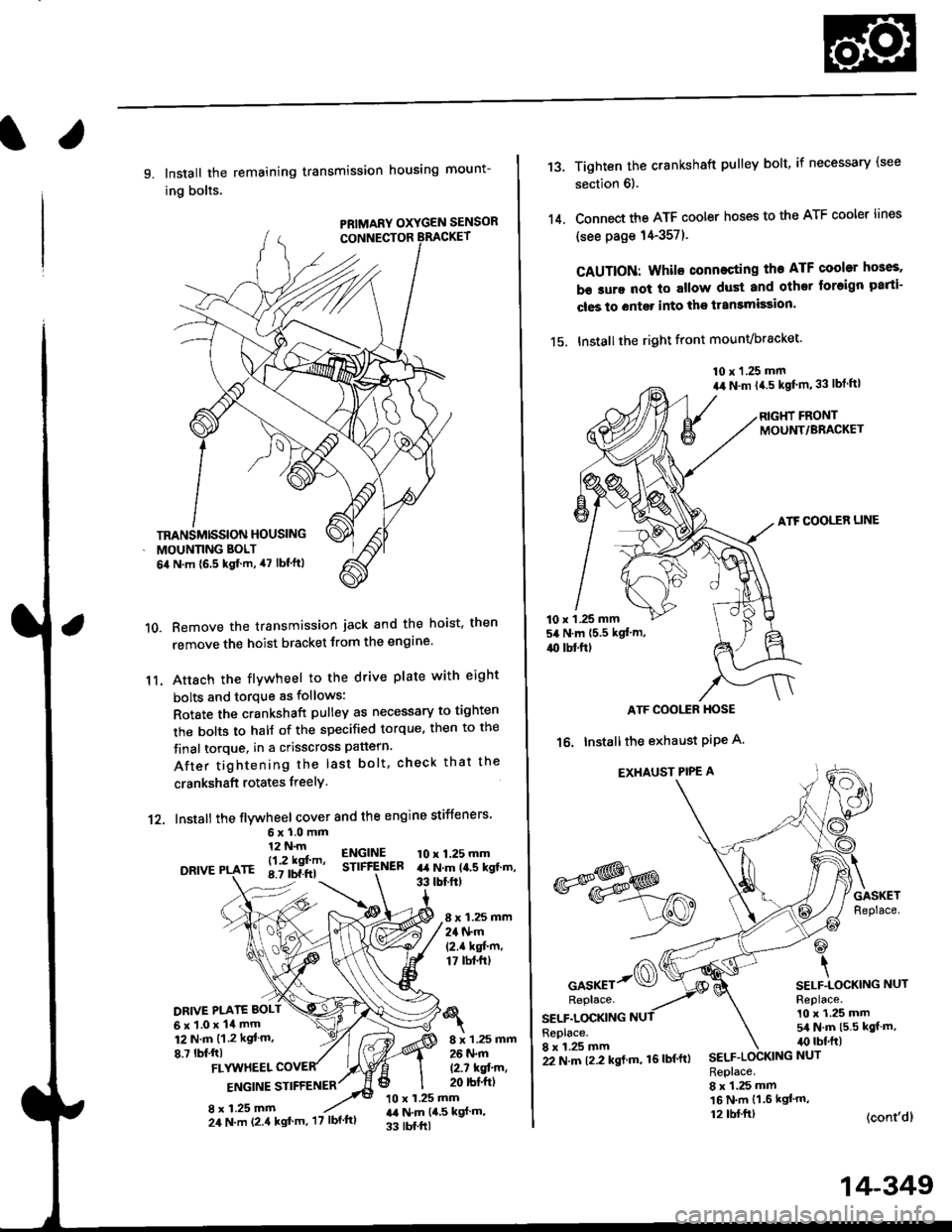
9. Install the remaining transmission housing mount-
ing bolts.
PRIMARY OXYGEN SENSOR
Remove the transmission jack and the hoist. then
remove the hoist bracket from the engine'
Attach the flvwheel to the drive plate with eight
bolts and torque as follows:
Rotate the crankshaft pulley as necessary to tighten
rhe bolts to half of the specified torque, then to the
final torque, in a crisscross pattern.
After tightening the last bolt. check that the
crankshaft rotates freelY.
10.
11.
12. Install the flywheel cover and the engine stiffeners
DRIVE
6xl.0mm12 N.m
- l12 kgf'm'rE 8.7 tbf.ftl
ENGINESTIFfENEB10 x 1.25 mmart N.m la.s kgt.m,33 tbtftt
8 x 1.25 mm24 N.m(2.1 kgf'm,17 tbt.ftt
DRIVE PI.ATE BOLT
6x1.0x14mm12 N.m {1.2 kgt m.
8.7 lbf,ftl8 x 1.25 mm26 N.m
12.7 kqfin,20 rbt'ftlFLYUTHEEL
ENGINE STIFFENER
8 x 1.25 mm10 x 1.25 mmr,a N.m {4,5 kgf m,
33 tbf.ftl
TRANSMISSION HOUSING
MOUNNNG BOLT
6il N.m {6.5 kgf.m, 47 lbf'ftl
24 N.m (2.4 kgt'm, '17 lbf'ftl
22 N.m t2.2 kgl m, 16lbf'ftl
14-349
13.
14.
Tighten the crankshaft pulley bolt, if necessary (see
section 6).
Connect the ATF cooler hoses to the ATF cooler lines
(see page 14-357).
CAUTION: Whilo connecting the ATF cooltr hGes,
b€ sure not lo allow dust and other loreign parti-
cles to entg. into the transmission.
15. Installthe right front mounvbracket'
10 x 1.25 mm
a,r N.m {4.5 kgf'm,33 lbt ftl
RIGHT FRONTMOUNT/BRACKET
ATF COOLER LINE
10 x 1 .25 mm54 N.m {5.5 kgt'm,
4{) tbl.ftt
ATF COOI,TR HOSE
16. Installthe exhaust PiPe A.
EXHAUST PIPE A
GASKETReplace.
@
\SELF.LOCKING NUTReplace.10 x 1.25 mm5/a N.m {5.5 kgt m,irc lbf.ft)
(cont'dl
*s$o
oor*rr-@Replace.
SELF.LOCKINGReplace.8 x 1.25 mmSELF.LOCKING NUT
Replace.8 x 1.25 mm16 N.m {1.6 kgl'm,12 tbl.ftt
Page 1028 of 2189

Transmission
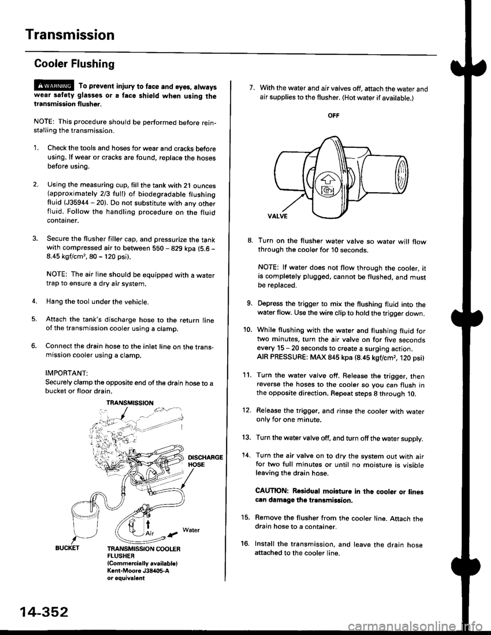
Gooler Flushing
@ To prevent iniury to face and eyes, alwayswear safety glasses or a tace shield when using thetransmission flusher.
NOTE: This procedure should be performed before rein-stalling the transmission.
'1. Check the tools and hoses for wear and cracks before
using. lf wear or cracks are found, reDlace the hoses
before using.
4.
Using the measuring cup. fill the tank with 2,1 ounces(approximately 2/3 full) of biodegradable flushingfluid (J35944 - 20). Do not substitute with any otherfluid. Follow the handling procedure on the fluidcontatner.
Secure the flusher filler cap, and pressurize the tankwith compressed air to between 5S0 - 829 kpa (5.6 -
8.45 kgf/cm'�, 80 - 120 psi).
NOTE: The air line should be equipped with a watertrap to ensure a dry air system,
Hang the tool under the vehicle.
Attach the tank's discharge hose to the return lineoi the transmission cooler using a clamp.
Connect the drain hose to the inlet line on the trans-mission cooler using a clamp.
IMPORTANT:
Securely clamp the opposite end ofthe drain hose to abucket or floor drain,
t
TRANSMISSION COOLERFLUSHER{Commercially available)Kent-Moore J384O5-Aor oouivalent
TRANSMISSION
14-352
7. With the water and air valves off, attach the water andair supplies to the flusher. (Hot water if available.)
8. Turn on the flusher water valve so water will flowthrough the cooler for 10 seconds.
NOTE: lf water does not flow through the cooler, itis completely plugged, cannot be flushed, and mustbe replsced.
9. Depress the trigger to mix the flushing fluid into thewater flow. Use the wire clip to hold the trigger down.
'10. While flushing with the water and flushing fluid fortwo minutes. turn the air valve on for five secondsevery 15 - 20 seconds to create a surging action.AIR PRESSURE: MAX 845 kpa (8.45 kgflcmr, 120 psi)
11. Turn the water valve off. Release the trigger, thenreverse the hoses to the cooler so you can flush inthe opposite direction. Repeat steps 8 through 10.
12. Release the trigger. and rinse the cooler with wateronly for one minute.
13, Turn the water valve off, and turn off the water supply.
'14. Turn the air valve on to dry the system out with airfor two full minutes or until no moisture is visibleleaving the drain hose.
CAUTION: Rosidual mobturo in the qooler or linescln damage the transmission,
15. Remove the flusher from the cooler line. Attach thedrain hose to a container.
16. Install the transmission. and leave the drain hoseattached to the cooler line.
Page 1033 of 2189

Shift Indicator PanelATF Gooler/Hoses
Adjustment
1.Check that the index mark on the indicator aligns
with the E mark on the shift indicator panel when
the transmission is in NEUTRAL.
lf not aligned, remove the front console {see section
20).
Remove the shift indicator panel mounting
and adjust by moving the panel.
NOTE: Whenever the shift indicator panel is removed,
reinstallthe Danel as described above.
It,
14-357
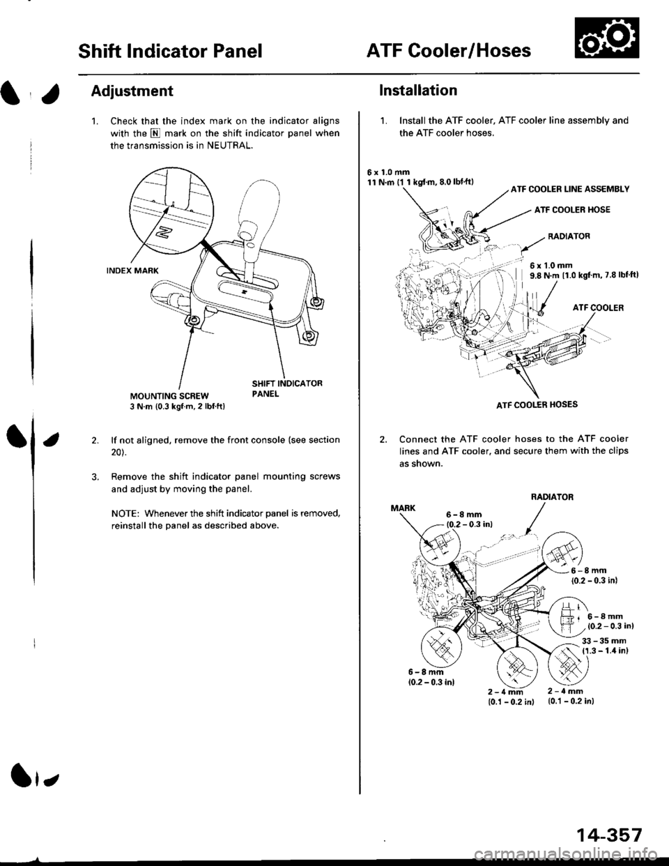
lnstallation
1. Installthe ATF cooler, ATF cooler line assembly and
the ATF cooler hoses.
6x1.0mm11 N.m ('l 1 kgf.m,8.0lbl'ftlATF COOLER LINE ASSEMBLY
ATF COOLER HOSE
RADIATOR
6x1.0mm9.8 N.m 11.0 kgf'm, 7 8 lbf'ft)
ATF COOLER
Connect the ATF cooler
lines and ATF cooler. and
as shown.
hoses to the ATF cooler
secure them with the clips
1l lTf{il.T
6-8mm10.2 - 0.3 in)
33-35mm11.3 - 1.4 inl
2-1mm10.1 - 0.2 in)
2-ilmm{0.1 - 0.2 in)
ATF COOI..ER HOSES