1998 HONDA CIVIC ECU
[x] Cancel search: ECUPage 992 of 2189

l.
'1.
2.
5.
6.
7.
Remove the ATF cooler inlet iine bracket bolt'
Remove the ATF cooler outlet line
Remove the ATF pan (fourteen bolts).
Remove the ATF strainer {two bolts)
Remove the one bolt securing the solenoid harness
connector, then push the connector.
Remove the lower valve body (eight bolts)
Clean the inlet opening of the ATF strainer thoroughly
with compressed air, then check that it is in good
condition, and the inlet opening is not clogged'
ATF STRAINER
INLET OPENING
Replace the ATF strainer if it is clogged or damaged
NOTE: The ATF strainer can be reused it it is not
clogged.
2c'
c;2 ar\
14-315
Page 994 of 2189

)
1.Remove the ATF passage line holder assembly'
Remove the flywheel housing (twenty bolts)'
Remove the ATF passage line assembly (one bolt)
Remove the ATF pump drive sprocket (three bolts),
then remove the ATF pump drive chaan.
Move the pitot flange toward its cutout, then remove
the pitot flange.
PITOT PIPE
Remove the snap ring securing the ATF pump drlve
sprocket hub. then remove the 22 x 28 mm thrust
shim, the ATF pump drive sprocket hub and the thrust
wasners,
Remove the differential assemblY.
Remove the park pawl shaft, the park pawl spring,
and the park Pawl'
Remove the snap ring securing the start clutch, then
remove the cotter retainer and the cotters.
7.
9.
J
14-317
10. Set the special tool on the start clutch' and attach the
oawl of the special tool to the park gear securely as
shown.
CAUTION:
. Do not place tho pawl of the spocial tool on the
start clutch guidc. ll the pawl ot the spocial tool
contacts the 3tart clutch guid€, the start clutch
guido may be damaged.
. Be sure not to allow dust and other foreign par-
ticles to enter into the drivon pull6y shaft'
START CLUTCHREMOVER07TAE - P4V0120
11.Remove the start clutch and the secondary drive
gear assembly using the special tool, then remove
the secondary gear shaft.
START CLUTCHREMOVER07TAE - P4V0120
START CLUTCHASSEMBLYReplace.
START CLUTCHASSEMBLY
PAWL
Page 996 of 2189
l.
1.
2.
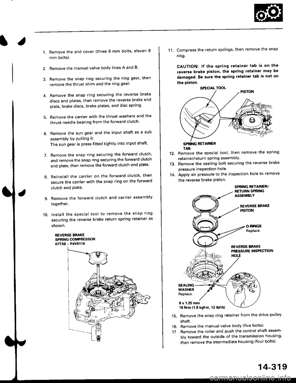
Remove the end cover {three 6 mm bolts, eleven 8
mm bolts).
Remove the manualvalve body lines A and B
3. Remove the snap ring securing the ring gear, then
remove the thrust shim and the ring gear'
4. Remove the snap ring securing the reverse brake
discs and plates, then remove the reverse brake end
plate. brake discs, brake plates, and disc spring'
5. Remove the carrier with the thrust washers and the
thrust needle bearing from the forward clutch
6. Remove the sun gear and the input shaft as a sub
assembly bY Pulling it
The sun gear is press fitted tightly into input shaft'
7. Remove the snap ring securing the forward clutch,
and remove the snap ring securing the forward clutch
end plate, then remove the forward clutch end plate'
8. Reinstall the carrier on the forward clutch, then
secure the carrier with the snap ring on the forward
clutch end Plate.
9. Remove the forward clutch and carrier assembly
together.
'10. lnstall the special tool to remove the snap ring
securing the reverse brake return spring retainer as
snown.
REVERSE BBAKESPRING COMPRESSOR07TAE - PaV0110
11. Compress the return springs. then remove the snap
ring
CAUTION: lf the spring retainer tab is on the
rsverse braks piston, tho spting letainer may be
damaged. Be surs the spring letainer tab is not on
the piston.
SPfiING FETAIiGRTAB
Remove the special tool, then remove the spring
retainer/return spring assembly.
Remove the sealing bolt securing the reverse brake
pressure insPection hole.
Apply air pressure to the inspection hole to remove
the reverse brake Piston
12.
13.
14.
16.'t7
SPBING REYAINER/RETURiI SPRIiIGASSEMALY
REVERSE BNAXEPISTON
o-RrllcsReplace.
FCVERSE BRAKEPRESSURE INS?ECTK)NHOtl
SEALINGWASHERReplace.
8 x 1.25 mm18 N.m 11.8 kgf.m, 13 lbf.ttl
Remove the snap ring retainer from the drive pulley
shaft.
Remove the manual valve body (five bolts)'
Remove the roller and push the control shaft assem-
bly toward the outside of the transmission housing,
then remove the intermediate housing (four bolts)'
SPECIAL TOOL
14-319
Page 1015 of 2189
1.
7.
lnstall the ATF feed pipe in the transmission hous-
ing, and install the three ATF feed pipes with new
O-rings in the transmission housing,
Install the two dowel pins and new transmission hous-
ing gasket on the transmission housing.
Push the control shaft assembly toward the outside
of the transmission housing, then install the inter-
mediate housing assembly (four bolts).
lnstall the manual valve body separator plate and
the two dowel pins on the intermediate housing,
then install the rnanual valve body with the detent
spring (five bolts).
Put the control shaft assembly back, then install the
roller in the intermediate housing.
lnstall the reverse brake piston in the intermediate
housing.
Install the spring retainer/return spring assembly on
the reverse brake Piston.
NOTE: Installthe return springs on the spring guides
of the reverse brake piston securely
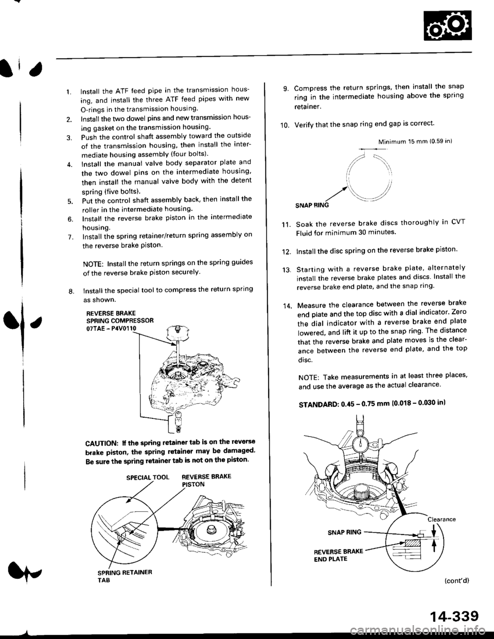
tnstall the special tool to compress the return spring
as shown.
REVERSE BRAKESPRING COMPRESSOR07TAE - P4V0110
6.
L
1
CAUTION: lf the spring retainer tab is on the reverse
brakc piston, the spring rstainer may be damaged'
Be sure the spring retainer tab is not on the piston'
rp
SPECIALTOOL REVERSEBRAKE
-^
14-339
10.
9.
14.
Compress the return springs, then install the snap
ring in the intermediate housing above the spring
retainer.
Verify that the snap ring end gap is correct'
Mini
/,,- '-t,,,,.
// \i/ ',r
'1 ,
.r' //'/. .-J?RINGSNAP
mum 15 mm 10.59 in)
Soak the reverse brake discs thoroughly in CVT
Fluid for minimum 30 minutes.
Installthe disc spring on the reverse brake piston'
Starting with a reverse brake plate, alternately
install the reverse brake plates and discs lnstall the
reverse brake end plate, and the snap ring'
Measure the clearance between the reverse brake
end plate and the top disc with a dial indicator' Zero
the dial indicator with a reverse brake end plate
lowered, and lift it up to the snap ring The distance
that the reverse brake and plate moves is the clear-
ance between the reverse end plate, and the top
disc.
NOTE: Take measurements in at least three places'
and use the average as the actual clearance'
STANDARD: 0.45 - 0.75 mm (0.018 - 0'030 in)
{cont'd)
11.
12.
13.
Page 1019 of 2189
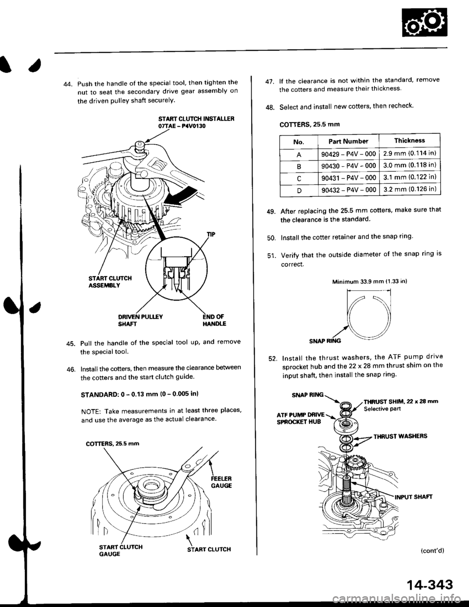
44. Push the handle of the special tool, then tighten the
nut to seal the secondary drive gear assembly on
the driven pulleY shaft securelY.
STAAT CLUTCH Ii'ISTALIIR07TAE - PaV0130
OF
46.
SHAFTHA'{DI,-E
Pull the handle of the special tool up, and remove
the special tool.
lnstallthe cotters, then measure the clearance Delween
the cotters and the start clutch guide
STANDARD: 0 - 0.13 mm (0 - 0.005 inl
NOTE: Take measurements in at least three places,
and use the average as the actual clearance
GAUGE
lil(il
COTTERS, 25.5 mm
START 1
GAUGCSTART CLUTCH
14-343
47.
48.
lf the clearance is not within the standard, remove
the cotters and measure their thickness
Select and install new cotters, then recheck.
COTTERS, 25.5 mm
After replacing the 25.5 mm cotters, make sure that
the clearance is the standard
lnstall the cotter retainer and the snap rlng
Verify that the outside diameter of the snap ring is
correct.
Minimum 33.9 mm (1.33 in)
SNAP RII{G
lnstall the thrust washers. the ATF pump drrve
sprocket hub and the 22 x 28 mm thrust shim on the
inDUt shaft, then install the snap ring.
49.
50.
52.
THRUST WASXERS
INPUT SHAFT
(cont'd)
No.Part NumberThickness
90429-P4V-0002.9mm(0.114 in)
B90430-P4V-0003.0mm(0.118 in)
c90431 -P4V-0003.1 mm (0.122 ln)
D90432-P4V-0003.2 mm (0.126 in)
SNAPRING\
ATF PUMP DRIVESPROCKET HUB
THFUST SHIM, 22 x 2a mm
Selective pan
Page 1024 of 2189
Transmission
Installation
Flush the ATF cooler as described on pages 14-352and 14-353.
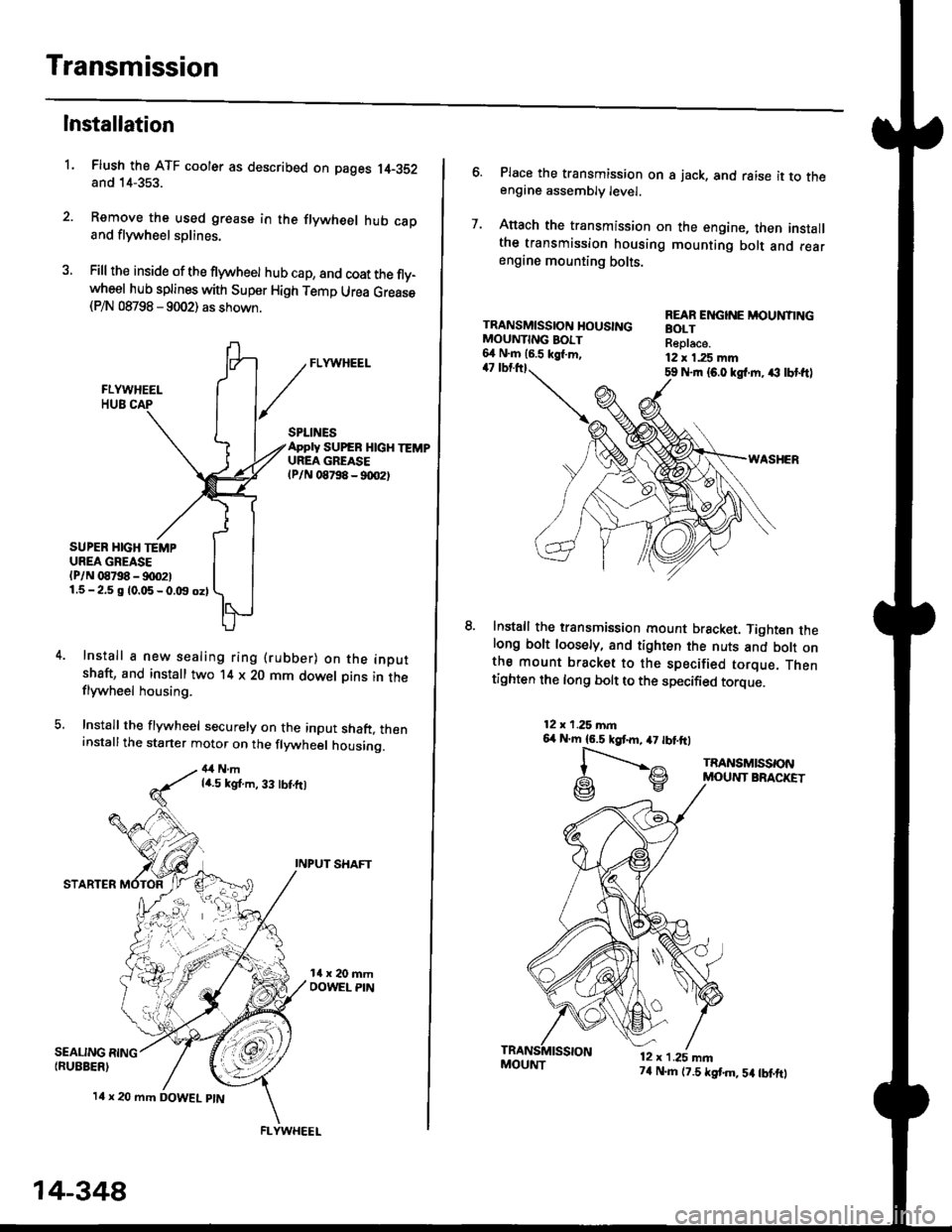
Remove the used grease in the flywheel hub caDand flywheel splines.
Fill the inside of the flywheel hub cap, and coat the fly-wheel hub splines with Super High Temp Urea Grease(P/N 08798 - 9002) as shown.
L
SEALING RING{RUEBER)
SPLINESApply SUPEB HlcH TEMPUREA GREASElPlN 08798 - 90O2t
SUPER HIGH TEMPUREA GREASE(P/N 08798 - !)00211.5-2.5 g 10.05-0.t9 oz)
Install a new sealing ring (rubber) on the inoutshaft, and install two '14 x 20 mm dowel Dins in theflywheel housing.
Install the flywheel securely on the input shaft, theninstallthe starter motor on the flywheel housing.
4,1Nmla.5 kgt.m, 33 tbt.ft)
INPUT SHAFT
STARTER
l4 x 20 mm DOWEL ptN
.4;i "lrj
,i rr,"r., ., a
14-348
FLYWHEEL
MOUI{T74 N.m (7.5 tstm,5a tbtftt
6. Place the transmission on s jack, and raise it to theengine assembly level.
7. Anach the transmission on the engine, then installthe transmission housing mounting bolt and rearengine mounting bolts.
TRANSMISSION HOUSINGMOUNTING BOIT6,1 N.m 16.5 kgl.m,47 tbtttl59 Nrn {6.0 kgl.m. ,€ lbt ftl
WASHER
lnstall the transmission mount bracket. Tighten thelong bolt loosely, and tighten the nuts and bott onthe mount bracket to the specified torque. Thentighten the long bolt to the specified torque.
REAR ENGINE MOUNTINGBOLTReplace.12 x 1.25 mm
12x 1.25 mn6,r N'm 16.5 kgtm,47 tbtftl
l-".--..-,^
G\V
TRANSMISSONMOUNT BRACKET
12 x 1.25 mn
Page 1028 of 2189
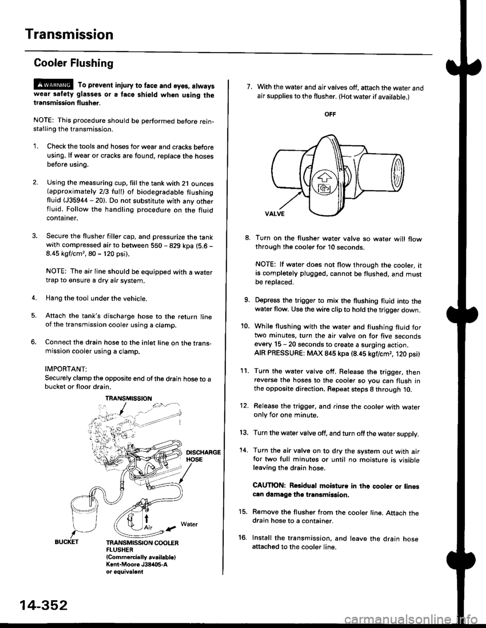
Transmission
Gooler Flushing
@ To prevent iniury to face and eyes, alwayswear safety glasses or a tace shield when using thetransmission flusher.
NOTE: This procedure should be performed before rein-stalling the transmission.
'1. Check the tools and hoses for wear and cracks before
using. lf wear or cracks are found, reDlace the hoses
before using.
4.
Using the measuring cup. fill the tank with 2,1 ounces(approximately 2/3 full) of biodegradable flushingfluid (J35944 - 20). Do not substitute with any otherfluid. Follow the handling procedure on the fluidcontatner.
Secure the flusher filler cap, and pressurize the tankwith compressed air to between 5S0 - 829 kpa (5.6 -
8.45 kgf/cm'�, 80 - 120 psi).
NOTE: The air line should be equipped with a watertrap to ensure a dry air system,
Hang the tool under the vehicle.
Attach the tank's discharge hose to the return lineoi the transmission cooler using a clamp.
Connect the drain hose to the inlet line on the trans-mission cooler using a clamp.
IMPORTANT:
Securely clamp the opposite end ofthe drain hose to abucket or floor drain,
t
TRANSMISSION COOLERFLUSHER{Commercially available)Kent-Moore J384O5-Aor oouivalent
TRANSMISSION
14-352
7. With the water and air valves off, attach the water andair supplies to the flusher. (Hot water if available.)
8. Turn on the flusher water valve so water will flowthrough the cooler for 10 seconds.
NOTE: lf water does not flow through the cooler, itis completely plugged, cannot be flushed, and mustbe replsced.
9. Depress the trigger to mix the flushing fluid into thewater flow. Use the wire clip to hold the trigger down.
'10. While flushing with the water and flushing fluid fortwo minutes. turn the air valve on for five secondsevery 15 - 20 seconds to create a surging action.AIR PRESSURE: MAX 845 kpa (8.45 kgflcmr, 120 psi)
11. Turn the water valve off. Release the trigger, thenreverse the hoses to the cooler so you can flush inthe opposite direction. Repeat steps 8 through 10.
12. Release the trigger. and rinse the cooler with wateronly for one minute.
13, Turn the water valve off, and turn off the water supply.
'14. Turn the air valve on to dry the system out with airfor two full minutes or until no moisture is visibleleaving the drain hose.
CAUTION: Rosidual mobturo in the qooler or linescln damage the transmission,
15. Remove the flusher from the cooler line. Attach thedrain hose to a container.
16. Install the transmission. and leave the drain hoseattached to the cooler line.
Page 1029 of 2189
![HONDA CIVIC 1998 6.G Workshop Manual l.
17.Make sure the transmission is in the E] position.
Fill the transmission with cvT Fluid, and run the
engine for 30 seconds or until approximately 0 95 {
(1.0 US qt.,0.8 lmp qt.) is discharged.
Re HONDA CIVIC 1998 6.G Workshop Manual l.
17.Make sure the transmission is in the E] position.
Fill the transmission with cvT Fluid, and run the
engine for 30 seconds or until approximately 0 95 {
(1.0 US qt.,0.8 lmp qt.) is discharged.
Re](/manual-img/13/6068/w960_6068-1028.png)
l.
17.Make sure the transmission is in the E] position.
Fill the transmission with cvT Fluid, and run the
engine for 30 seconds or until approximately 0 95 {
(1.0 US qt.,0.8 lmp qt.) is discharged.
Remove the drain hose, and reconnect the cooler
return hose to the transmission (see page 14-355)
Refill the transmission with CVT Fluid to the proper
level (see page 14-299).
18.
'19.
.l ,
TOOL MAINTENANCE
1. Empty and rinse after each use. Fill the can with water
and pressurize the can. Flush the discharge line to
ensure that the unit is clean.
2, lf discharge liquid does not foam, the orifice may be
blocked.
3. To clean, disconnect the plumbing from the tank at
the large couPling nut.
FILTER
\
\- 0--D
i
I
O.RING
Remove the in-line tilter from the discharge side and
clean if necessary'
The fluid orifice is located behind the filter. Clean it
with the pick stored in the bottom of the tank han-
dle. or blow it clean with air. Securely reassemble
all parts.
COUPLINGNUT
II
-@q
\ORIFICE
FILLER CAP
14-353