Page 786 of 2189

Mai nshaft/Cou ntershaft
Linear Solenoid AssemblySpeed Sensors
Replacement
1. Remove the mounting bolts and the linear solenoid
assemory.
Clean the mounting surfaceand flu id passages.
6x1.0mm12 N.m 11.2 kgl m,8.7 tbf.ftl
@
@
GASKET
Clean the mounting surface and fluid passage of the
linear solenoid assembly and transmission housing.
Install a new linear solenoid assembly with a new
gasl(et.
NOTE; Do not pinch the gasket when installing the
linear solenoid; make sure that the gasket is installedproperly in the mounting groove of the linear sole-
noid.
Check the linear solenoid connector for rust, dirt or
oil, and connect it securely,
LINEARSOLENOIDASSEMELY
I
14-108
Replacement
't.
6x128.7
Remove the 6 mm bolt and the countershaft speed
sensor from the right side cover.
COUNTERSI{AFTSPEED SENSOR
O.RINGReplace.
MAINSHAFTSPEEDSENSOR
MAINSHAFT SPEEDSENSOB WAS}IER(D16Y7 enginel
6x1.0mm12 N.m (1.2 kgf m,8.7 tbf.ft)
1.0 mmN.m (1.2 kgf.m,rbf ft)
\\
/,
%/E:)
Remove the 6 mm bolt and the mainshaft sDeed
sensor from the transmission housino.
Replace the O-ring with a new one before installing
the countershaft speed sensor or th€ mainshaft speed
sensor.
NOTE: Installthe mainshaft speed sensor washer on
the mainshaft speed sensor. The mainshaft speed
sensor washer is used on models with the D'|6Y7
engine.
Page 797 of 2189

Pressure Testing
@I While testing, be caroful of th€ rotating front wheels.
. Make sure lifts, iacks, and satoty stands are placod properly (see section 1)'
CAUTION:
. Beforo iesting, be sure the transmission fluid is tilled to tho proper level'
. Warm up tho engine before testing'
1. Raise the vehicle (see section 1).
2. Warm up the engine, then stop the engine and connect a tachometer'
3. Connect the oil pressure gauges to each inspection hole.
TOROUE: 18 N.m (1.8 kgf'm, 13 lbnft)
cAUTloN: connact the oil pressuro gauges securely; be suro not to allow dust and other foreign Parlicles to entel
the inspestion holos'
A/T OIL PRESSURE GAUGESET w/PANEL07t06 - 0020400
A/T LOW PRESSURE GAUGE
SET WPANEL07406 - 0070300
A/T OIL PRESSURE HOSEADAPTER07Mru - PY0120(4 requiJedl
A/T OIL PBESSURE HOSE
2210 mmOTMAJ - PY4{)llA
14 roquircdl
Start the engine, and measure the respective ptessure as follows'
a Line Pressure
. 1st Clutch Pressure
. 2nd,3rd and 4th Clutch Pressure
Install a new washer and the sealing bolt in the inspection hole. and tighten to the specified torque'
TOROUE: l8 N.m (1.8 kgf'm,13lbf'ft)
NOTE: Do not reuse old sealing washers; always replace washers'
(cont'd)
14-119
Page 798 of 2189
Pressure Testing
(cont'd)
Line Pressure/1st Clutch Pressurc Measurement
1. Set the parking brake, and btock both rear wheels securely.
2. Start the engine, and run it at 2,OOO rpm.
3. Shift to N or E position, then measure line pressure.
NoTE: Higher pressure may be indicated if measurements are made in shift lever positions other than @ or @ positron.
4. Shift to tq;l position, hold the engine at 2,000 rpm, and measure 1st crutch pressure.
1ST CLUTCH PRESSUREINSPECTION HOLE(Marked with "1")
LOCK.UP CONTROLSOLENOID VALVE A/8ASSEMBLY
VALVE A/B ASSEMBLY
PRESSURESHIFT LEVER
POS|TtONSYMPTOMPROBABLE CAUSEFLUID PRESSURE
StandardService Limit
LineN orENo (or low)
lrne pressureTorque converter,
ATF pump, pres-
sure regutator.
torque converter
check valve
830 - 880 kPa
{8.5 - 9.0 kgf/cm?,
120 - 130 psi)
780 kPa(8.0 kgf/cm'�, 110 psi)
1st ClutchD;lNo or low 1st
pressure
1st Clutch
\
14-120
Page 799 of 2189
2nd, 3rd and 4th Clutch Pressure Measurement
1. Set the parking brake, and block both rear wheels securely'
2. Start the engine, and run it the engine at 2,000 rpm'
3. Shift to E position, then measure 2nd clutch pressure
4. Shiftto El position, then measure3rd clutch pressure
5. Shift to E position, then measure 4th clutch pressure'
6. Shift to E position, then measure 4th clutch pressure'
INSPECTION HOI'E(Marked with "3")
2ND CLUTCH PR€SSURE
INSPECTION HOLE
FLUID PRESSURE
standard I sorviqe LimitPRESSURESHIFT LEVER
POStT|()NSYMPTOMPROBABLE CAUSE
2nd ClutchtrNo or low 2nd
pressure
2nd Clutch800 - 850 kPa
(8.2 - 8.7 kgflcm'�,
120 - 120 psi)
760 kPa
(7.7 kgf/cm'�, 110 Psil
3rd ClutchtrNo or low 3rd
pressure
3rd Clutch8'�10 - 860 kPa
(8.3 - 8.8 kgt/cm',
120 - 130 psi)
760 kPa
(7.8 kgt/cm', 110 Psi)
4th clutchp.lNo or low 4th
presSure
4th clurch
EServo Valve or 4th
Clutch
1+121
Page 811 of 2189

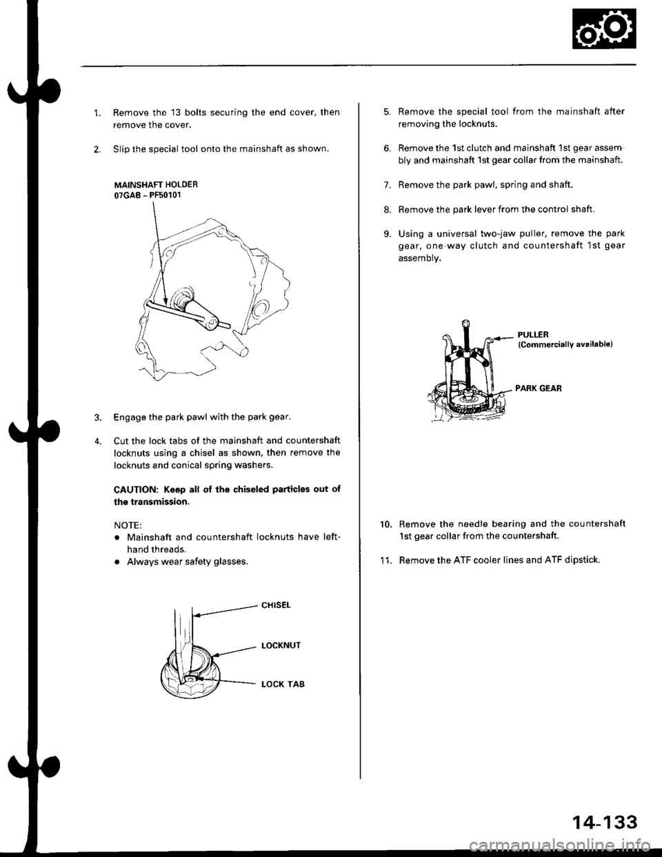
1.Remove the 13 bolts securing the end cover, then
remove the cover.
Slip the special tool onto the mainshaft as shown.
MAINSHAFT HOLOER
07GAB - PFs0101
Engage the park pawl with the park gear.
Cut the lock tabs of the mainshaft and countershaft
locknuts using a chisel as shown. then remove the
locknuts and conical spring washers
CAUTION: Keep all of lhe chiseled particles out of
the transmission.
NOTE:
. Mainshaft and countershaft locknuts have left-
hand threads.
. Always wear safety glasses.
4.
cHrs€L
LOCKNUT
LOCK TA8
5.
6.
11.
Remove the special tool from the mainshaft after
removing the locknuts.
Remove the 1st clutch and mainshaft 1st gear assem
bly and mainshaft 1st gear collar from the mainshaft.
7. Remove the park pawl. spring and shaft.
8. Remove the park lever from the control shaft.
9. Using a universal two-jaw puller, remove the park
gear, one way clutch and countershaft 1st gear
assemory.
PULLER(CommerciallY available)
PARK GEAR
10.Remove the needle bearing and the countershaft
1st gear collar from the countershaft
Remove the ATF cooler lines and ATF dipstick.
14-133
Page 818 of 2189
Valve
Assembly
NOTE:
Coat all parts with ATF before assembly.
. Install the valve, valve spring and cap in the valve
body and secure with the roller.
5-'--------P/-_^?=w_
=/ /- ( ,. )l_/1 -,.1)
VALVE BODY
VALVE AODY
VALVE
h
14-140
SPRING
. Set the spring in the valve and install it in the valve
body. Push the spring in with a screwdriver, theninstall the spring seat.
SPRIITG SEAT
VALVE BODY
Install the valve, spring and cap in the valve body.
Push the cap, then installthe clip.
Page 861 of 2189

Transmission
1.
lnstallation
Flush the ATF cooler as described on page l4-187
and 14-188.
Install the torque converter assembly securely with
a new O-ring on the mainshaft
STARTER MOTOR
14 mm DOWEL PIN
TOROUE O-RING
CONVERTER Replace
lnstall the starter motor on
housing, then install the two
the torque converter housing.
lil mm DOWEL PIN
the torque converter
14 mm dowsl pins in
MOUNTINGBRACKET
Place the transmission on a jack, and raise it to the
engine assembly level.
Attach the transmission to the engine, then install
two transmission housing mounting bolts and two
rear engine mounting bolts.REAR ENGINEMOUNNNG BOLTS1,1r15mm&| N.m 18.5 kgf m, 61 lbf'ft]
Replace.
64 N.m {6.547 tbf frlWASHER
ENGINE
TRANSMISSION HOUSINGMOUNTING BOLTS12 x 1.25 mm
45 N.m {4.5 kgf.m,
JACK
6. Install the transmission mount bracket.
12 x 1.25 mm6il N.m {6.5 kgf.m, a7 lbf'ft)
12 x 1.25 mm74 N.m (7.5 kgf.m,54 tbt.fr)
TRANSMISSION MOUNT
7.Install the remaining transmission housing mount-
ing bolts and remaining rear engine mounting bolt.
REAR ENGINEMOUNTING BOLT14 x 1.5 mmel N.m (8.5 kgt'm,61 tbl.ft)Replace.
HOUSING
MOUNTING BOLTS12 x 1.25 mmg N m (6.5 kgf m, 'l? lblftl
8. Remove the transmission jack.
(cont'd)
14-183
Page 865 of 2189

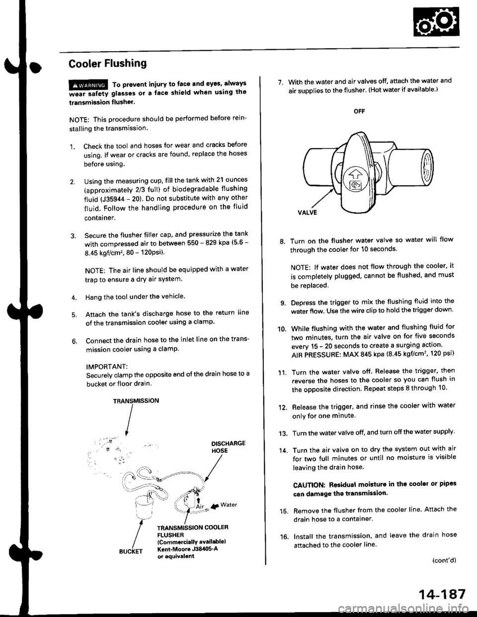
Cooler Flushing
!!!@ To prevent iniury to. face and eyas, always
-ea. safetv glasses ot a face shield when using the
transmission flusher.
NOTE: This procedure should be performed before rein-
stalling the transmission.
1. Check the tool and hoses for wear and cracks before
using. lf wear or cracks are found, replace the hoses
before using.
Using the measuring cup, fill the tank with 2'l ounces
(approximately 2/3 full) of biodegradable flushing
fluid (J35944 - 20). Do not substitute with any other
fluid. Follow the handling procedure on the fluid
contarner.
Secure the flusher filler cap, and pressurize the tank
with compressed air to between 550 - 829 kpa (5 6 -
8.45 kgflcm'�. 80 - 120Psi).
NOTE: The air line should be equipped with a water
trap to ensure a dry air system.
Hang the tool under the vehicle.
Attach the tank's discharge hose to the return line
of the transmission cooler using a clamp.
Connect the drain hose to the inlet line on the trans-
mission cooler using a clamP
IMPORTANT:
Securely clamp the opposite end oJ the drain hose to a
bucket or floor drain.
TRAMtssroN
TRANSMISSION COOLERFLUSHER{Commcrci.llY avail.blel
Kent-Moore J384O5'Aor equivelent
NS
I
{r Water
7. With the water and air valves off, attach the water and
air suDolies to the flusher' lHot water if available.)
8, Turn on the flusher water valve so water will flow
through the cooler for 10 seconds.
NOTE; lf water does not tlow through the cooler, it
is completely plugged. cannot be flushed, and must
be replaced.
9. Depress the trigger to mix the flushing fluid into the
water flow. Use the wire clip to hold the trigger down'
While flushing with the water and flushing fluid for
two minutes, turn the air valve on for five seconds
everv 15 - 20 seconds to create a surging action'
AIR PRESSURE: MAX 845 kpa {8.45 kgf/cm'�, 120 psi)
Turn the water valve off. Release the trigger, then
reverse the hoses to the cooler so you can flush in
the opposite direction. Repeat steps 8 through 10'
12, Release the trigger, and rinse the cooler with water
onlv for one minute
13. Turn the water valve off, and turn off the water supply
14. Turn the air valve on to dry the system out with air
for two full minutes or until no moisture is visible
leaving the drain hose.
CAUTION: Residual mobturo in tho cooler or pipas
can damage the transmksion'
15. Remove the flusher from the cooler line. Attach the
drain hose to a contalner.
16. Install the transmission, and leave the drain hose
attached to the cooler line
{cont'd)
10.
'11.
14-187