Page 1623 of 2189

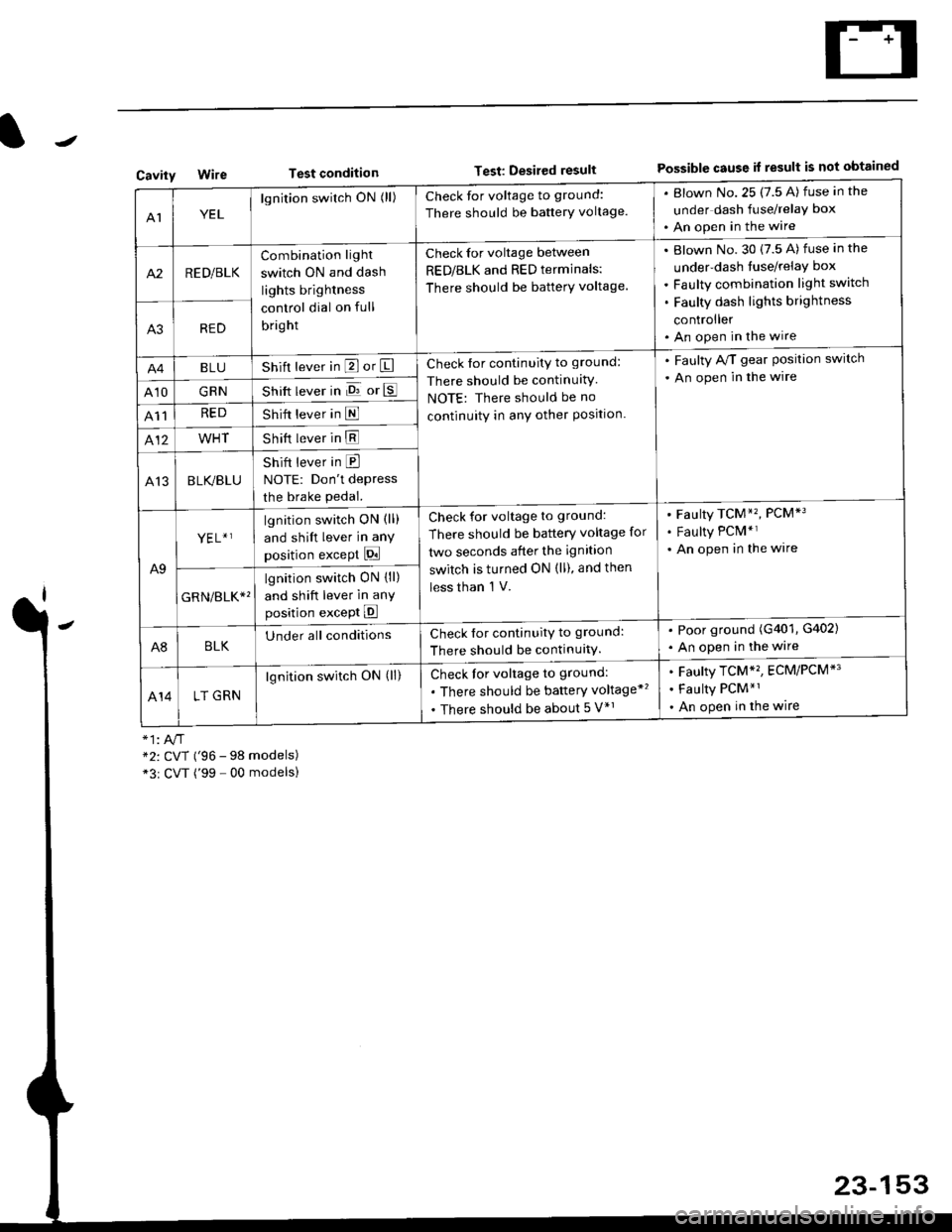
Test conditionTest: Desired resultPossible cause it result is not obtainedCavity
AIYEL
lgnition switch ON (ll)Check for voltage to ground:
There should be banerY voltage.
. Blown No.25 (7.5 A) fuse in the
under dash fuse/relay box
. An open in the wire
A2RED/BLK
Combination light
switch ON and dash
lights brightness
control dial on full
bright
Check for voltage between
RED/BLK and RED terminals:
There should be batterY voltage.
Blown No. 30 {7.5 A) fuse in the
under-dash tuse/relay box
Faulty combination light switch
Faulty dash lights brightness
controller
An open in the wireA3RED
BLUShift lever in P or ICheck for continuity to ground:
There should be continuitY
NOTE: There should be no
continuity in anY other Position.
. Faulty A/T gear Position switch
. An open in the wire
A10GRNShift lever in E or E
A11REDShift lever in E
412WHTShift lever in E
A13BLK/BLU
Shift lever in E
NOTE: Don't depress
the brake pedal.
A9
YEL+ ]lgnition switch ON (ll)
and shift lever in any
position except Pi
Check for voltage to ground:
There should be battery voltage for
two seconds after the ignition
switch is turned ON (ll), and then
less than 'l V.
Faulty TCM*'�, PCM*3
Faulty PCM*r
An open in the wire
GRN/err*'
lgnition switch ON {ll)
and shift lever in anY
position except E
A8BLKUnder all conditionsCheck for continuitv to ground:
There should be continuitY.
. Poor ground (G401, G402)
. An open in the wire
414LT GRN
lgnition switch ON (ll)Check for voltage to ground:
. There should be baftery voltage*'�
. There should be about 5 V*r
Faulty TCM*'�, ECM/PCM*'
Faulty PCM*1
An open in the wire
*2: CVT ('96 - 98 models)*3r CVT ('99 - 00 modelsl
23-153
Page 1626 of 2189
Integrated Control Unit
UNDER,DASH FUS€/RELAY 8OX
IGNITION SWITCH
I wNDSHTELD II wrPEtuwAsHEF II swrTcH I
i Y **i,,*I wHT,tsLK II t_+
JV
Circuit Diagram
INTEGRATED CONTROL UNIT
8LK
G40tG402
WINOSHIELD WIPER/WASHER S-W|iCI.] ,
OFF/INT INT
f7 Y7
IIlltl
ttBLU/BLK YEUELU
ELUMHT
I
I
WINDSHIELDWIPEBMOTOH(As)
* 1 : Wilh mmbrned wiper washer operalion*2 : 96-98 models
UNDES H@O FUSE/RELAY BOX
6
,8-q
INTEEMITTENTWIPER RELAYCIRCUIT
"J COMBINEOWIPER.WASHENctncutT
WINOSHIELDWASHERMOTOR
23-156
Page 1639 of 2189
'99 - 00 models
1. Clean the outer lens so that you can see the center
of the headlights (A).
l,-
2. Park the vehicle in front of a wall or a screen (A).
A
4.
Open the hood.
Turn the horizontal adjuster so that the arrow on
the horizontal indicator gear (A) is pointing up.
7.5 m (25 ft)
Page 1641 of 2189
Taillights
Replacement (Except'99 - 00 Sedanl
NOTE:
. Inspect the gasket; replace it il it is distorted or stays
compressed.
. After installing the taillights, run water over them to
make sure they do not leak.
Outer Taillights ('96 - 00 models, except'99 - 00 Sedan):
1. Open the trunk lid/hatch.
2. Disconnect the 4P or 6P connector trom the outer
taillight.
3. Remove the four mounting nuts, then pull out the
outer taillight.
l-
Hatchback:
BRAKE/TAILLIGHT: 2115W
TURN SIGNAL LIGHT: 21 W
BACK-UP LIGHT: 21 W
4P or 6P CONNECTOR
BRAKE/TAILLIGHT: 2115W
TURN SIGNAL LIGHT: 21 W
BRAKEiTAILLIGHT: 2115 W
BACK-UP LIGHT: 21 W
Inner Taillights (Coupe'96 - 00 models/Sedan'96 - 98
models):
1. Open the trunk lid, then remove the access panel.
2. Disconnect the 4P connector from the inner taillight.
3. Remove the four [three] mounting nuts, then pull
out the inner taillight.
I l: Sedan
Coupei
INNER TAILLIGHT
Sedan:
INNER TAILLIGHT
4P CONNECTOB
Page 1645 of 2189
Hazard Warning Switch Test
CAUTION: Be careful not to damage the hazard warn-
ing switch or the center outlet panel when prying the
switch out.
'96 - 98 models:
'1. Pry the hazard warning switch out of the center out-
let panel.
2. Disconnect the 'l0P connector from the hazard warn-
ing switch.
3. Check for continuity between the terminals in each
switch position according to the table
HAZARDWARNINGlOP CONNECTOR
q-
Check for continuity between the terminals in
switch position according to the table.
Terminal No,4 is not used.
Terminal
t** \
12356I9l0
OFFoo
ot !.1o
ONo-ooo
o.o
o@o
'99 - 00 models:
1. Remove the center panel lsee section 20).
2. Remove the two screws, then remove the switch
from the center Panel
scREwsHAZARDWARNINGswlTcH
CENTER PANEL
.
Page 1657 of 2189
Stereo Sound System
Component Location Index
SRS components are located in this area. Review the SRS component locations, precautions. and procedures in the SRS
section (24) before performing repairs or service.
'96 - 98 models
AUDIO UNIT(STEFEO RADIO TUNERIBeplacement, page 23 189Terminals, page 23-190
ANTENNA MASTReplacement, page 23 193
RIGHT TWEETERReplacement, Page 23 191
LEFT TWEETERReplacement, Page 23 191
ANTENNA LEAD
LEFT FRONT SPEAKER
Replacement, Page 23'191
SUB
RIGHT FRONT SPEAKERReplacement, page 23'191
ANTENNALEAD
CASSETTE PLAYER
Replacement, Page 23-189REAR SPEAKERSReplacement, page 23- 19'l
(cont'd)
23-147
q-
Page 1658 of 2189
Stereo Sound System
Component Location Index {cont'd)
SRS components are located ln this area. Review the SRS component locations, precautions, and orocedures in the sRSsection (24) before perlorming repairs or service.
'99 - 00 models
AUDIO UNITFeplacement, page 23-189Terminals, page 23-190
ANTENNA MAST (Coupe/Hatchbeck)Replacement, page 23,193RIGHT TWEETERReplacement, p6ge 23-191
LEFT TWEETERReplacement, page 23-191
ANTENNA LEAD
LEFT FRONTReplacement, page 23-191
RIGHT FRONT SPEAKERReplacernent, page 23-191
WINDOW ANTENNA {SedanlWire Test, page 23 192Wire Repair, page 23-192
SUB
I.TAO
REAR SPEAKERSReplacemont, page 23-191
23-1AA
Page 1659 of 2189
UNDER DASHFUSE/RELAY 80X
r*.i,,";l
I
I
I
I
I
I
IYEUFEDWHTiELU
Circuit Diagram ('96 - 98 modelsl
A15A16
NoJ0 (7 sA)
v
IRED]BLK
RED
I
I
I
J
DASH LIGHTSBRIGHTNESSCONTROLLER
ANTENNALEAD
BRN/WHTBLK
G501
LEFT FHONTDOOF SPEAKER
I RED,^/Er
ILI�l
RIGHT REARSPEAKER
I BLU/YEL
III�t
SPEAKER
q-
IGN TION SWITCHUNDER.HOOD FUSE/FELAY BOX
AUDIO UN T(STEREO RAOLO TUNER)
@
LEFTRIGHTTWEETER
GRY]BLK
23-189