Page 1559 of 2189
lgnition Switch
4.
Test
SRS components are located in this area Review the
SRS component locations. precautions. and procedures
in the SRS section {24} before performing repairs or ser-
1. i/ake sure you have the anti-theft code for the
radio, then write down the frequencies for the
radio's preset buttons ('99 - 00 models).
2. Disconnect the battery negative cable.
3. Remove the driver's dashboard lower cover and
knee bolster (see section 20).
Disconnect the 5P connector from the under dash
fuse/relay box and the 7P connector from the main
wire harness.
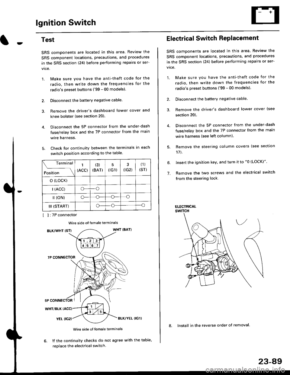
Check for continuity between the terminals in each
switch position according to the table.
I I :7P connector
Wire side ot female terminals
BLK/WHT {STIWHT IBAT}
7P CONNECTOR
WHT/BLK
YEL (IG2}BLK/YEL {IG1)
Wire side of female terminals
6. lf the continuity checks do not agree with the table,
replace the electrical switch.
Terminal
Position
1
(ACC)
(3)
(BAT)
5
{tG1) G2)
(1)
(sr)
o (LocK)
| (ACC)o--o
l (oN)o-o
III (START)o--o
1.
Electrical Switch RePlacement
SRS components are located in this area. Review the
SRS component locations, precautions, and procedures
in the SRS section \24) belore performing repairs or ser-
vtce.
1. Make sure you have the anti-theft code for the
radio, then write down the frequencies for the
radio's preset buttons {'99 - 00 modelsl.
2. Disconnect the battery negatlve cable.
3. Remove the driver's dashboard lower cover {see
section 20).
Disconnect the 5P connector from the under-dash
fuse/relay box and the 7P connector from the main
wire harness (see left column).
Remove the steering column covers {see section
11t.
lnsert the ignition key, and turn it to "0 {LOCK)".
Remove the two screws and the electrical switch
from the steering lock.
ELECTRICALswtTcH
8. Install in the reverse order of removal.
23-a9
Page 1560 of 2189
lgnition Switch
Steering Lock Replacement
SRS components are located in this area. Review theSRS component locations. precautions, and procedures
in the SRS section (24) before performing repairs or ser-vtce.
Remove:
LMake sure you have the anti-theft code for theradio, then wire down the frequencies for theradio's preset buttons ('99 - 00 models).
Disconnect the battery negative cable.
Remove the driver's dashboard lower cover andknee bolster (see section 20).
Disconnect the 5P connector from the under-dash
fuse/relay box and the 7P connector from the mainwire harness (see previous page).
Remove the steering column covers, then removethe mounting bolts and nuts from the steering col-umn (see section l7).
Lower the steering column assembly,
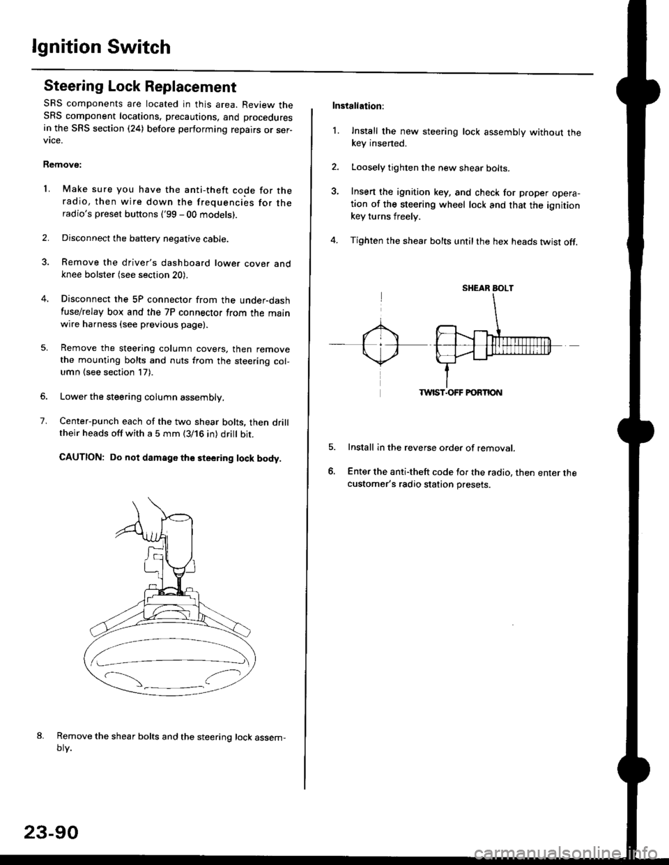
Center-punch each of the two shear bolts, then drilltheir heads off with a 5 mm (3/16 in) dritt bit.
CAUTION: Do not damago the steering lock body.
Remove the shear bolts and the steering lock assem,oty.
2.
1.
23-90
Installation:
l. Install the new steering lock assembly without thekey insened.
Loosely tighten the new shear bolts-
Insert the ignition key, and check for proper opera-tion of the steering wheel lock and that the ignitionkey turns freely.
Tighten the shear bolts untilthe hex heads twist off.
TWIST.OFF FORTION
Install in the reverse order of removar.
Enter the anti-theft code for the radio, then enter thecustomer's radio station presets.
sr{€aR SroLT
Page 1570 of 2189
Starting System
Starter Replacement
1.Make sure you have the anti-theft code for the
radio, then write down the frequencies for the
radio's preset buttons ('99 - 00 models).
Disconnect the battery negative cable.
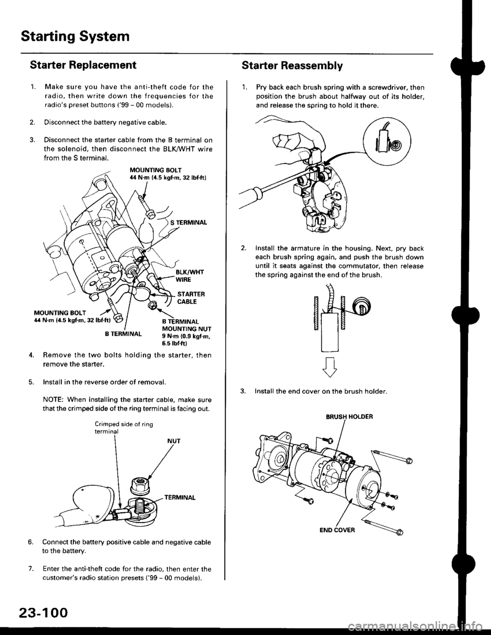
Disconnect the starter cable from the B terminal on
the solenoid, then disconnect the BLK trHT wire
from the S terminal.
MOUNTING BOLT44 N.m l/t.s kgf.m. 32 lbf.ft)
S TERMINAL
MOUNTING BOLT6,1 N.m {4.5 kstm.32lbtftl
MOUNTING NUT9 N,m {0.9 kgl.m,6.s lbtftl
B TERMINAL
4. Remove the two bolts holding the starter, then
remove the starter.
lnstall in the reverse order of removal.
NOTE: When installing the staner cable, make sure
that the crimped side ofthe ring terminal is facing out.
TERMINAL
Connect the battery positive cable and negative cable
to the battery.
Enter the anti-theft code for the radio, then enter the
customer's radio station presets ('99 - 00 models).
7.
Crimped side of ring
23-100
Starter Reassembly
'1. Pry back each brush spring with a screwdriver, then
position the brush about halfway out of its holder.
and release the spring to hold it there.
Install the armature in the housing. Next, pry back
each brush spring again, and push the brush down
until it seats against the commutator, then release
the spring against the end of the brush.
aw
3. Install the end cover on the brush holder.
ERUSH HOLDER
Page 1573 of 2189
lgnition System
-Circuit Diagram: '96 - 97 models
.i-
8LU
I
nBLU BLU I
tl
lnI TESTI TACHOMETEF\-7 CONNECTOR
TACHOMETERTCM (CW)
J-) {sh,eldinsr't I
tfYEL BBN/BLK
+l
I:
G101
$t+++
UNDER HOOD FUSE/ RELAY 8OX
BLh TEL YEL GBN
BLKlYEL
IAl
BLK/YEL YELIGFN
IGN]TIONCOL
TDCrTop dead cenlerCKP: Crankshall postionCYP Cylnder poslon
TDC]CKP]CYP SENSoR
" *]BLU'*2 WHI BLU
IGNITION CONIROLMODULE (CM)
/ Has b'r ll n\I iorse I
rUSE FE-AV BO}
*u r-. .-*---{<9ot # u,,."r. | |
\j/ El v
tl
23-103
Page 1574 of 2189
lgnition System
Circuit Diagram :'98-00 models
UNDER HOOD FUSUFELAY BOX'x'E;;;;-;;;;l /; l-*;- Ecw.cM
ffiwFnBLK<-wHr\9-
Y
tlBTKTYEL YEUGRN
IGN]TIONswtTcHUNDER,DASHFUSE/BELAY BOX
YEt
J
BLK
J
FED
+
*1 :H TACHI*2 :TEC
9 *IBLU'
23-104
Page 1587 of 2189
-
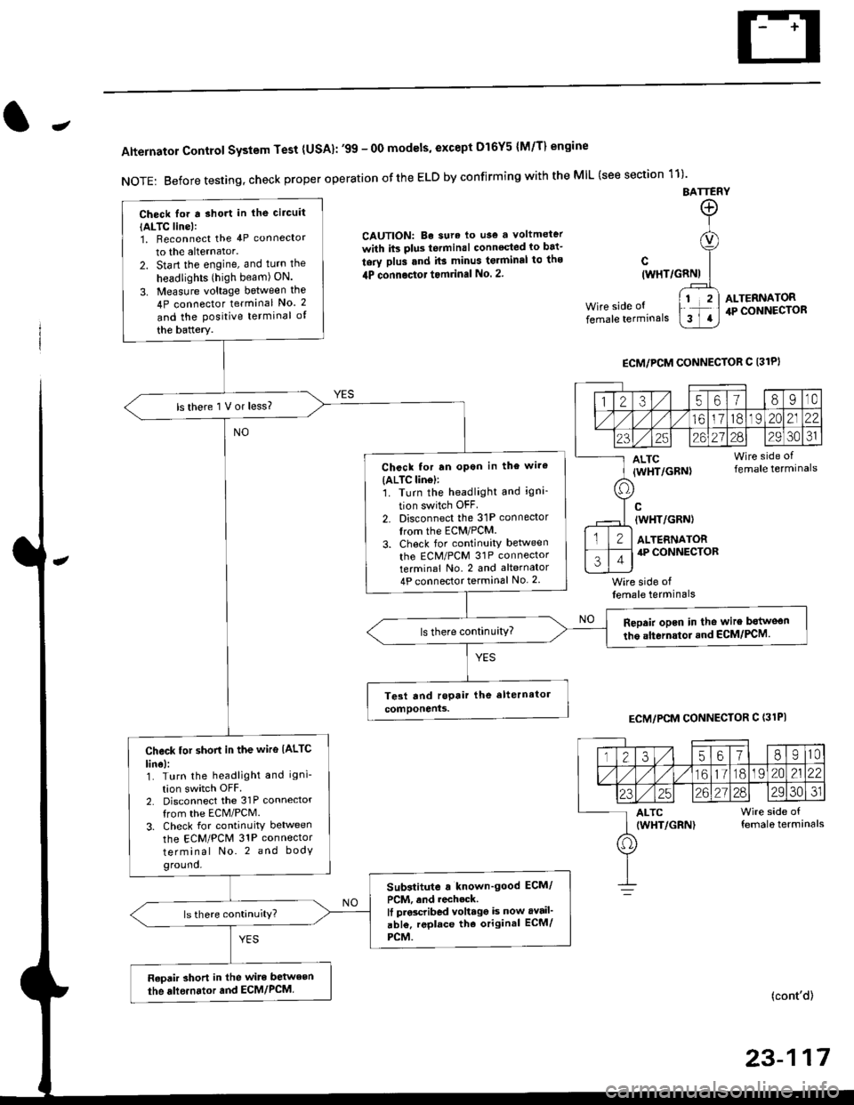
Alternator Control System Test {USA}: '99 - 0O models, except Dl6Y5 {M/T} engine
NOTE: Before testing, check proper operation ofthe ELD by confirming with the MIL (see section 11)'
BATTERY
CAUTION: Be sura lo use a voltmeter
with its plus te.minal conneqted io bat-
tery plus and it3 minus tgrminal to ths
4P connoctot tomrinal No. 2.
Wire side of
female terminals
c(WHT/GRNI
wire side offemale terminals
ALTERNATOR.P CONNECTOR
ECM/PCM CONNECTOR C 13lPI
ECM/PCM CONNECTOR C (31PI
(cont'd)
23-117
Check lor a sho.t in the circuit
{ALTC line):1, Beconnect the 4P connector
to the alternator.
2. Start the engine, and turn the
headlights (high beam) ON.
3. Measure voltage between the
4P connector terminal No. 2
and the Positive terminal of
the battery.
ls there 1 V or less?
Chcck for rn opon in the wire(ALTC lin6l:1. Turn the headlight and igni-
tion switch OFF
2. Disconnect the 31P connector
trom the ECM/PCM.
3. Check for continuity betlveen
the ECM/PCM 31P connectorterminal No. 2 and alternator
4P connector terminal No. 2
Repair opcn in the wire botweon
the alternstoi.nd ECM/PCM.ls there continuity?
Check tor short in the wire IALTC
line):1. Turn the headlight and igni-
tion switch OFF2. Disconnect the 31P connector
from the ECM/PCM.
3. Check for continuity between
the ECM/PCM 31P connector
terminal No. 2 and body
ground.
Substitute a known'good ECM/
PCM, and recheck.It prscribed voltagg is now avail'
abl€, replace tho original ECM/
PCM.
Raoair short in the wite between
the alle.nator and ECM/PCM,
1235618I10
/11611lo191 zo2122
23252621?82930JI
ALTC Wire side of(WHT/GRN) female terminals
o
Page 1590 of 2189
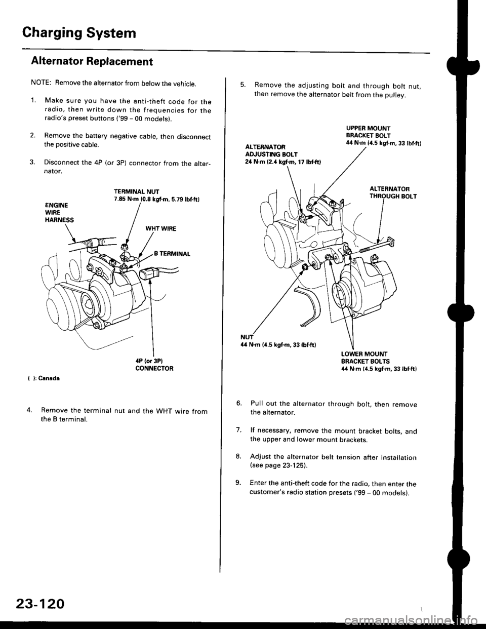
Charging System
Alternator Replacement
NOTE: Remove the alternator from below the vehicle.
'1. Make sure you have the anti-theft code for theradio, then write down the frequencies for theradio's preset buttons ('99 - 00 models).
2. Remove the battery negative cable, then disconnectthe positive cable.
3. Disconnect the 4P (or 3P) connector from the alter-naIor.
TERMINAL NUT7.85 N.m (0.8 kgf.m, 5.79lbf.ftl
{ }: Cansd.
4. Remove the terminal
the B terminal.
nut and the WHT wire from
23-120
5. Remove the adjusting bolt and through bolt nut,then remove the alternator belt from the Dullev.
UPPER MOUNTBRACKET BOLT44 N.m 14.5 kgt.m, 33 lbl.ftlALTERNATORAD.'USTING BOLT24 N.rh l2.a kgf.m, 17 lbtft)
ALTERNATORBOLT
a4 N.m 14.5 kstm.33lbf'ftl
LOWER MOUNTBRACKET BOLTSa4 N.m l{.5 kgf.m,33lbfft)
Pull out the alternator through bolt, then removethe alternator.
lf necessary, remove the mount bracket bolts. andthe upper and lower mount brackets
Adjust the alternator belt tension after installation(see page 23-125).
Enter the anti-theft code for the radio, then enter thecustomer's radio station presets ('99 - 00 models).
7.
Page 1620 of 2189
A/T Gear Position Indicator
UNDER.DASHFI.JSE/FELAY BOXIGNITIONswrrcH
Circuit Diagram
CW:
UNDER HOOD FUSE/RELAY BOX
6; |-;,,'r&l \o3o'75A
rr,/-TPLK+r,,'rirac coJ-aL("E1.<\c-t]
---
IY. PCM"
:i3M)''
V
ILT GRN
TqM 'l
f7v
tlYEL GFN
8LK
G401G442
*1 : 96'98 modeis+2 i '99t0 models
No 30 {7.5A)
V
IRED/BLK
t,
||l
| ,k sfi0f, |Itg)coNsotEl
I Y i1?ri I
tll
t'RED
I
I
vDASI| L GHTSERIGHTNESSCONTNOLLER
l./TGEAR POSITION INDICAToR (h lhe gauge assembty)
YYYY
A/TGEARPostTtoNswrTcH
A'/T GEAB POSITION NDICATOR OIMMING C]RCUIT
23-150