Page 1730 of 2189

Power Door Locks
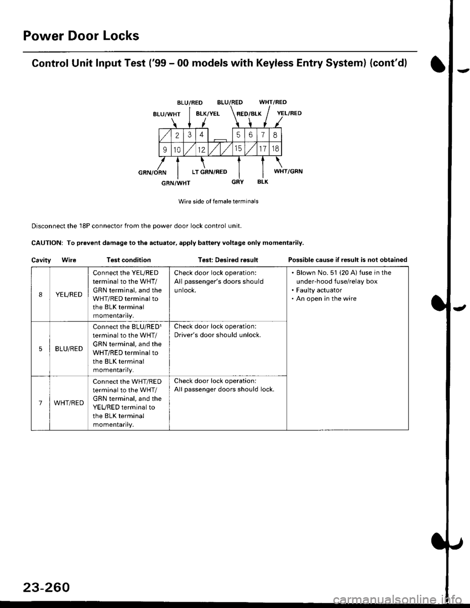
Control Unit Input Test ('99 - 00 models with Keyless Entry System) (cont'd)
BLU/RED WHT/RED
8LU/WHT8LK/YELRED/BLK
2345618
91012/t/t517td
LT GRN,/RED
BLK
Wire side of female terminals
Disconnect the 18P connector from the oower door lock control unit.
CAUTION: To prevent damage to the actuator, apply baftery voltage only momentarily.
Cavity WileTest conditionTest: Desired resultPossible cause if result is not obtained
BLU/RED
YEL/RED
WHT/GRN
GRN/WHT
IYEURED
Connect the YEURED
terminal to the WHT/
GRN terminal, and the
WHT/RED terminal to
the BLK terminal
momenraflty,
Check door lock operation:
All passenger's doors should
untocK.
Blown No. 51 (20 A) fuse in the
under-hood fuse/relay box
Faulty actuator
An open in the wire
5BLU/RED
Connect rhe BLU/RED1
terminal to the WHT/
GRN terminal, and the
WHT/RED terminal to
the BLK terminal
momenlaflry_
Check door lock operation:
Driver's door should unlock.
7WHT/RED
Connect the WHT/RED
terminal to the WHT/
GRN terminal, and the
YEURED terminal to
the BLK terminal
momenlaflry.
Check door lock operation:
All passenger doors should lock.
23-260
Page 1732 of 2189
Power Door Locks
Audio Unit {Keyless Receiver Circuitl Input Test ('96 - 98 models}
Remove the audio unit, then disconnect the A and B connectors (see page 23-189).
Inspect the connector and socket terminals to be sure they are all making good contact
. lf the terminals are bent, loose or corroded, repair them as necessary, and recheck the system
. lf the terminals look OK, make the following input tests at the connector.
- lf anv test indicates a problem, find and correct the cause, then recheck the system
lf all the inout tests prove OK, the control unit must be faulty; replace it.
A CONNECTOBB CONNECTOR
16P CONNECTORS
AUDIO UNIT
L
2.
WHT/BLU YEL/RED
{KEYLESS RECEIVER CIRCUIT}
23-262
Page 1734 of 2189
Power Door Locks
Audio Unit lKeyless Receiver
Circuitl Terminals ('96 - 98 modelsl
CavityWireDestination
16P CONNECTOR
B1BLU/REDlgnition key switch
*82LT GRNTrunk latch switch
Ft2BLU/YELUnlock (Driver's door)
B4BLUValet switch
*85LT BLUSecurity {lN)
B6BLK/YE LNo. 14 (7.5 A) fuse
*81ORNSecurity (D2)
B8LT GRN/BLKCeiling light
B9GRN/ORNUnlock (All doors)
810GRNA/VHTLock (OutPutl
*811BLU/WHTLED O
*812WHT/BLKSecurity (D0)
+B 13YEL/BLUSecurity (D'l )
814LT GRN/REDDoor switch
B15BLKG round (G401, G402)
o toGRYnorn
*: For security system (option)
23-264
Driver's Door Lock Switch Test
1. Remove the inner handle (see section 20).
2. Disconnect the 3P connector from the door lock
switch.
Check for continuity between the terminals in each
switch position according to the table.
DRIVER'SDOORLOCKswtTcH
Terminal
Position123
LOCKo-----o
OFF
UNLOCKo----o
Page 1737 of 2189

)
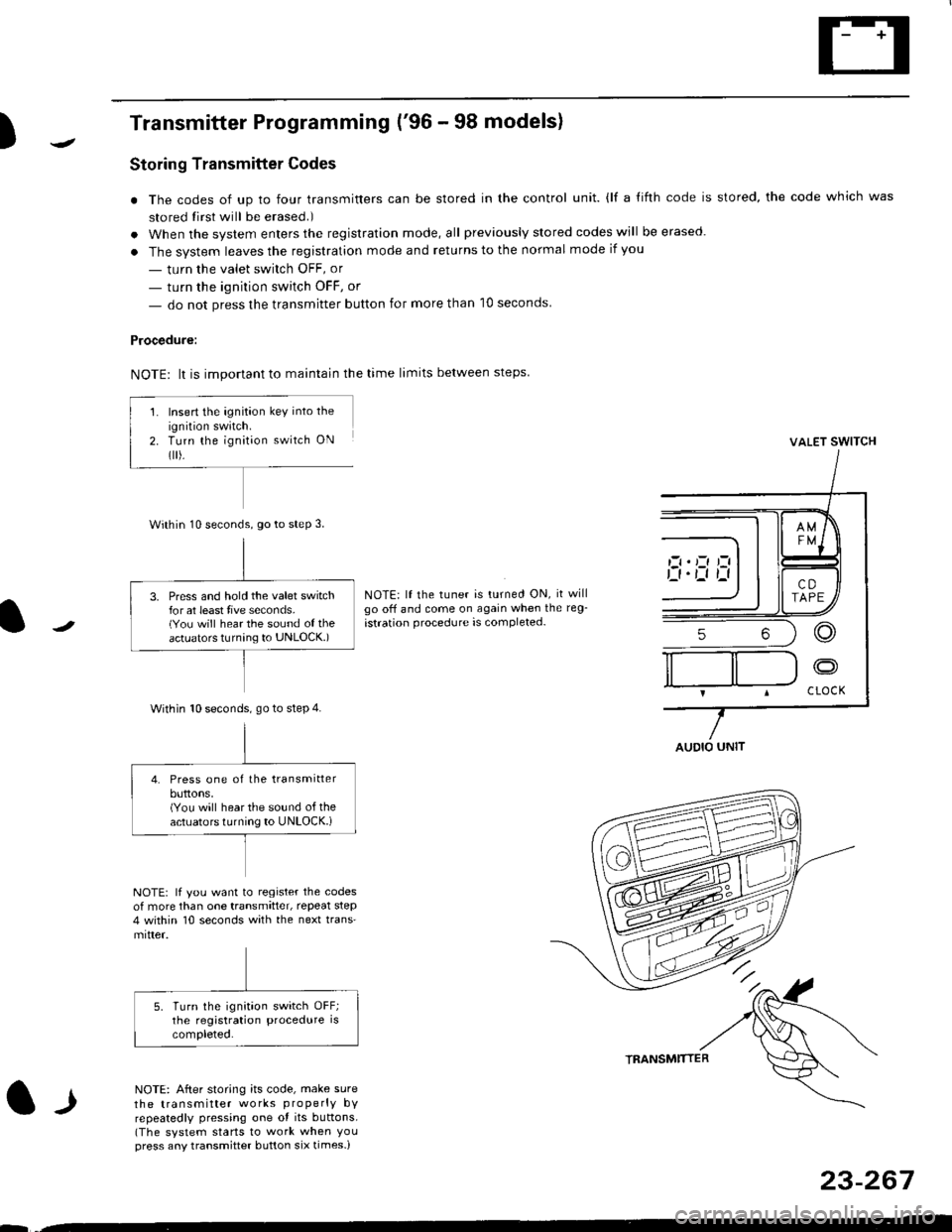
Transmitter Programming ('96 - 98 models)
Storing Transmitter Codes
. The codes of up to four transmitters can be stored in the control unit. {lf a {ifth code is stored, the code which was
stored tirst will be erased.)
. When the system enters the registration mode, all previously slored codes will be erased.
. The system leaves the registration mode and returns to the normal mode if you
- turn the valet swirch OFF, or
- turn the ignition switch OFF, or
- do not press the transmitter button for more than 10 seconds
Procedure:
NOTE: lt is important to maintain the time limits between steps
VALET SWITCH
NOTE: lf the tuner is turned ON, it willgo off and come on again when the reg-
istration procedure is completed-
l-l
NOTE: lf you want to register the codesof more than one transmitter, repeat step4 within 10 seconds with the next trans'mitter.
NOTE: After storing its code, make sure
the transmitter works properly bYrepeatedly pressing one ot its buttons.(The system starts to work when Youpress any transmitter button six times-)
TRANSMTITTER
23-267
--
Insert the ignition key into the
ignition swatch.Turn the ignit;on switch ON
flr).
Within 10 seconds, go to steP 3.
3. Press and hold the valet switchfor at least tive seconds.(You will hear the sound of theactuators turnang to UNLOCK.)
Within 10 seconds. go to step 4.
4. Press one of the transmitterbuttons,(You will hear the sound of theactuators turning to UNLOCK.i
AUDIO UNIT
Page 1738 of 2189

Power Door Locks
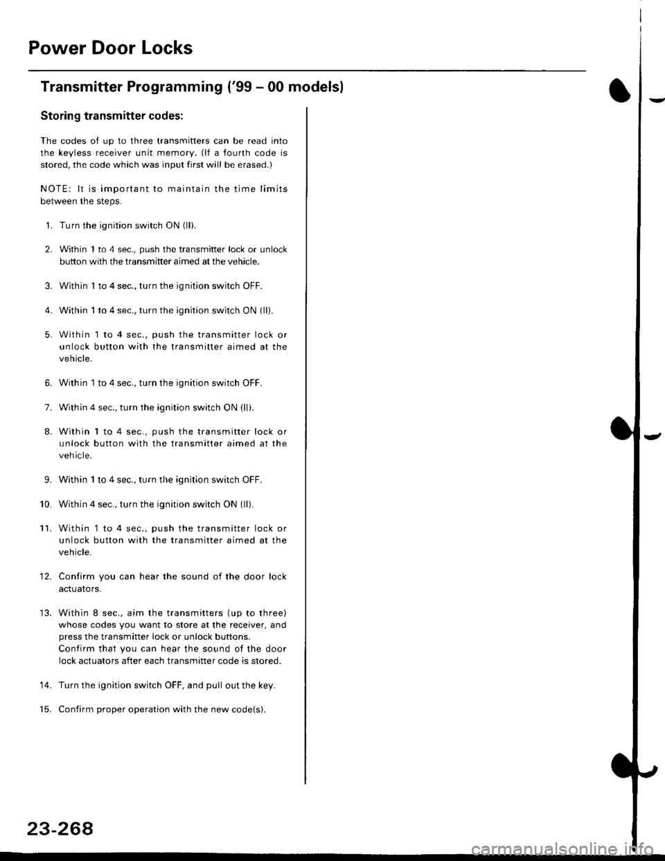
Transmitter Programming ('99 - 00 modelsl
Storing transmitter codes;
The codes of up to three transmitters can be read into
the keyless receiver unit memory. (lf a fourth code is
stored, the code which was input first will be erased.)
NOTE: lt is important to maintain the time limits
between the steps.
'1. Turn the ignition switch ON (ll).
2. Within 1 to 4 sec., push the transmitter lock or unlock
button with the transmitter aimed at the vehicle.
3. Within I to 4 sec., turn the ignition switch OFF.
4. Within 1 to 4 sec., turn the ignition switch ON 1ll).
5. Within 1 to 4 sec., push the transmitter lock or
unlock button with the transmitter aimed at the
vehicle.
6. Within 1 to 4 sec., turn the ignition switch OFF.
7. Within 4 sec., turn the ignition switch ON (ll).
8. Within 1 to 4 sec., push the transmitter lock or
unlock button with the transmitter aimed at the
vehicle.
9.Within 1 to 4 sec., turn the ignition switch OFF.
Within 4 sec., turn the ignition switch ON (ll).
Within '1 to 4 sec., push the transmitter lock or
unlock button with the transmitter aimed at the
vehicle.
Confirm you can hear the sound of the door lock
acIuarors.
Within 8 sec., aim the transmitters (up to three)
whose codes you want to store at the receiver, and
press the transmitter lock or unlock buttons.
Contirm that you can hear the sound of the door
lock actuators after each transmitter code is stored.
Turn the ignition switch OFF, and pull out the key.
Confirm proper operation with the new code(s).
'10.
11.
12.
14.
23-268
Page 1739 of 2189

)
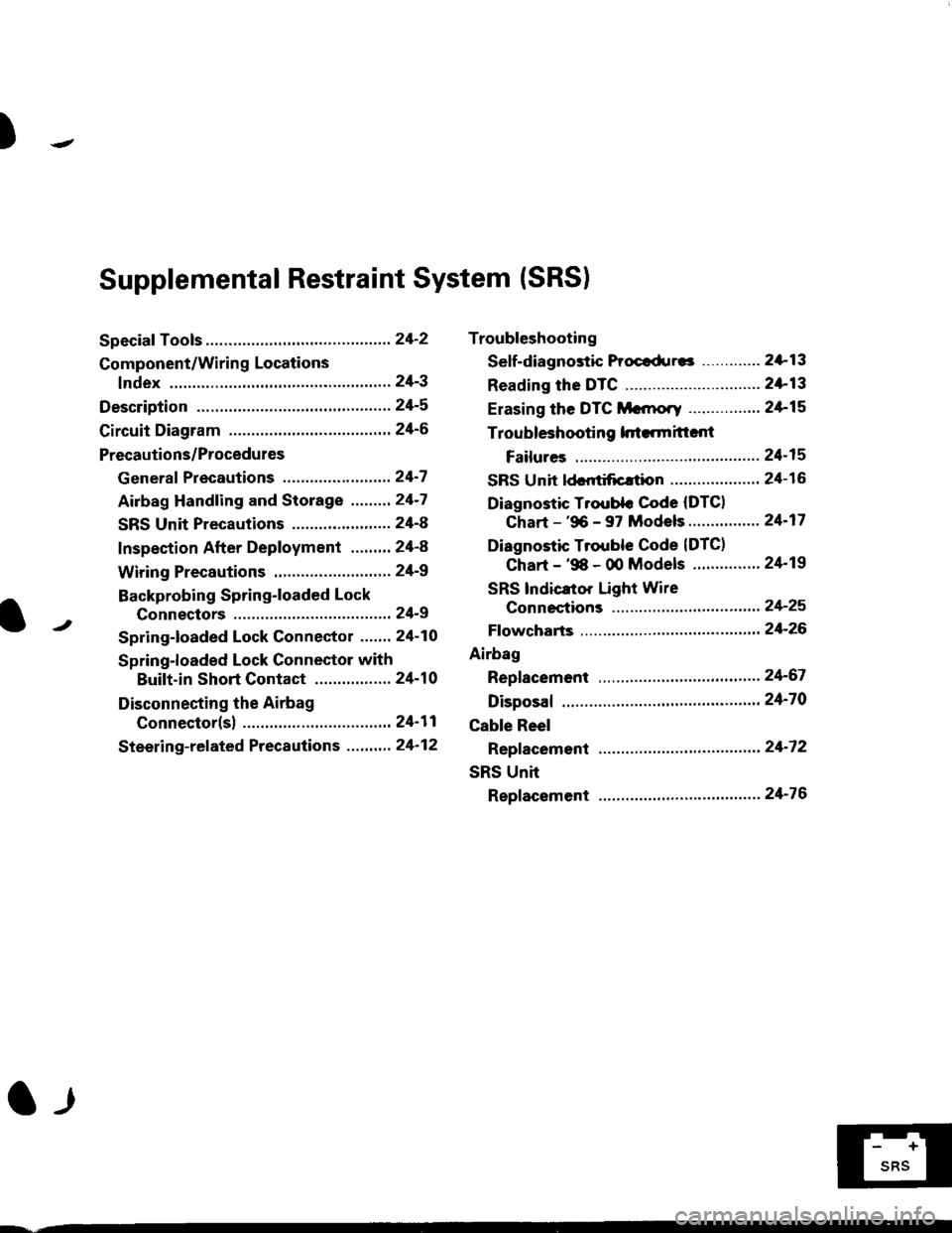
Troubleshooting
Sef f -dia gnostic Proctdurcs ............. 2+13
Reading the DTC .............................. 2+13
Erasing the DTC Mcnrory ................ 24-15
Troubleshooting h.ttnitt.nt
Failures ..............24-15
SRS U n it ldcntificrtion .................... 24- 1 6
Diagnostic Troublc Code (DTC)
Chart - '96 - 97 Models..."'."....... 24-17
Diagnostic Trouble Code (DTCI
Chart - '$ - 00 Models '.........""' 24'19
SRS lndicaror Light Wire
connections ...'.,24-25
Ff owcharts ........,,,,.24-26
Airbag
Repfacemant ...'.'...24-67
Disposaf .................24'70
Cable Reel
Repfacement .........24'72
SRS Unh
Repfacement ..'......24'76
l-l
-+
sRs
Supplemental Restraint System (SRSI
Speciaf Tools ... ...........24'2
Component/Wirin g Locations
fndex ................ ......24-3
Description ................ 24-5
Circuit Diagram ......." 24'6
Precautions/Procedures
Generaf Precautions ...............,,,,,,,.. 24-7
Airbag Handling and Storage .........24-7
SRS Unit Precautions ...................... 24-8
Inspection After Deployment ........' 24-8
Wiring Precautions ................... ....... 24'9
Backprobing Spring-loaded Lock
Connectors .......,24-9
Spring-loaded Lock Connectol ....,,. 24-10
Spring-loaded Lock Connector with
Built-in Short Contact ................. 24-10
Disconnecting the Airbag
Connector(sl .....' 24'11
Steering-related Precautions ...,.,.,,. 24'12
Page 1742 of 2189
Gomponent/Wiring Locations
Index: Without Front Passenger's Airbag (some Canada Modelsl
SRS INDICATOR LIGHT (ln the gauge assembly)Troubleshooting, page 24-13Gauge assembly, section 23
DRIVER'S AIRSAGReplacement,page 24-67Disposal, page 24-70
SRS UNITGROUNO
To HORN SWITCH
SRS MAIN HARNESS
SRS UNIT{lncluding safing sensorand impact sensor)Replacement. page 24,76
To CRUISE CONTROLSET/RESUME SWITCH
oo/ \oo
To DRIVER,S AIRBAG
DASHBOARD WIRE HARNESSto SRS INDICATOR LIGHT inGAUGE ASSEMBLY5P CONNECTOR
SERVICE CHECKCONNECTOR {2P}IB8N, BLKI
SRS MAINto UNDER-DASHFUSE/RELAY BOX2P CONNECTOR
SRS MAIN HARNESSto SRS UNIT18P CONNECTOR
SRS MAIN HARNESSto MAINWIREHARNESS3P CONNECTOR
MEMORY ERASE SIGNAL(MES) CONNECTON (2P'
IGRY, GRYI o. IGRN, GRNI
MAIN WIRE HARNESSto DASHBOARD WIRE HARNESS24P CONNECTOR
24-4
DUMMY RESISTOB
Page 1754 of 2189
Troubleshooting
SRS Unit ldentification
+: On '98 - 00 models, the troubleshooting procedures are different for each type of SRS unit. ldentifv the SRS unit in thevehicle using the chart below, then follow the proper flowchan in the following pages.
'98 - 00 Model SRS units
MAKERIDENTIFICATION
MARK*Remark
NECM1Driver's airbag only
M1Driver's & Passenger's airbags
KEIHINM2Driver's & Passenger's airbags
SIEMENSM3Driver's & Passenger's airbags
'96 - 97 Model SRS units
LABEL IIDENTIFICATION MARK)
MAKERPARTS NUMBERRemark
NEC77960-S04-C81Driver's airbag only
77960-S04-N81Driver's & Passenger's airbags
TAKATA77960-S04-N82Driver's & Passenger's airbags
SIEMENS77960-S02-A81Driver's & Passenger's airbags,'97 Model only
24-16
lr