Page 1135 of 2189

)
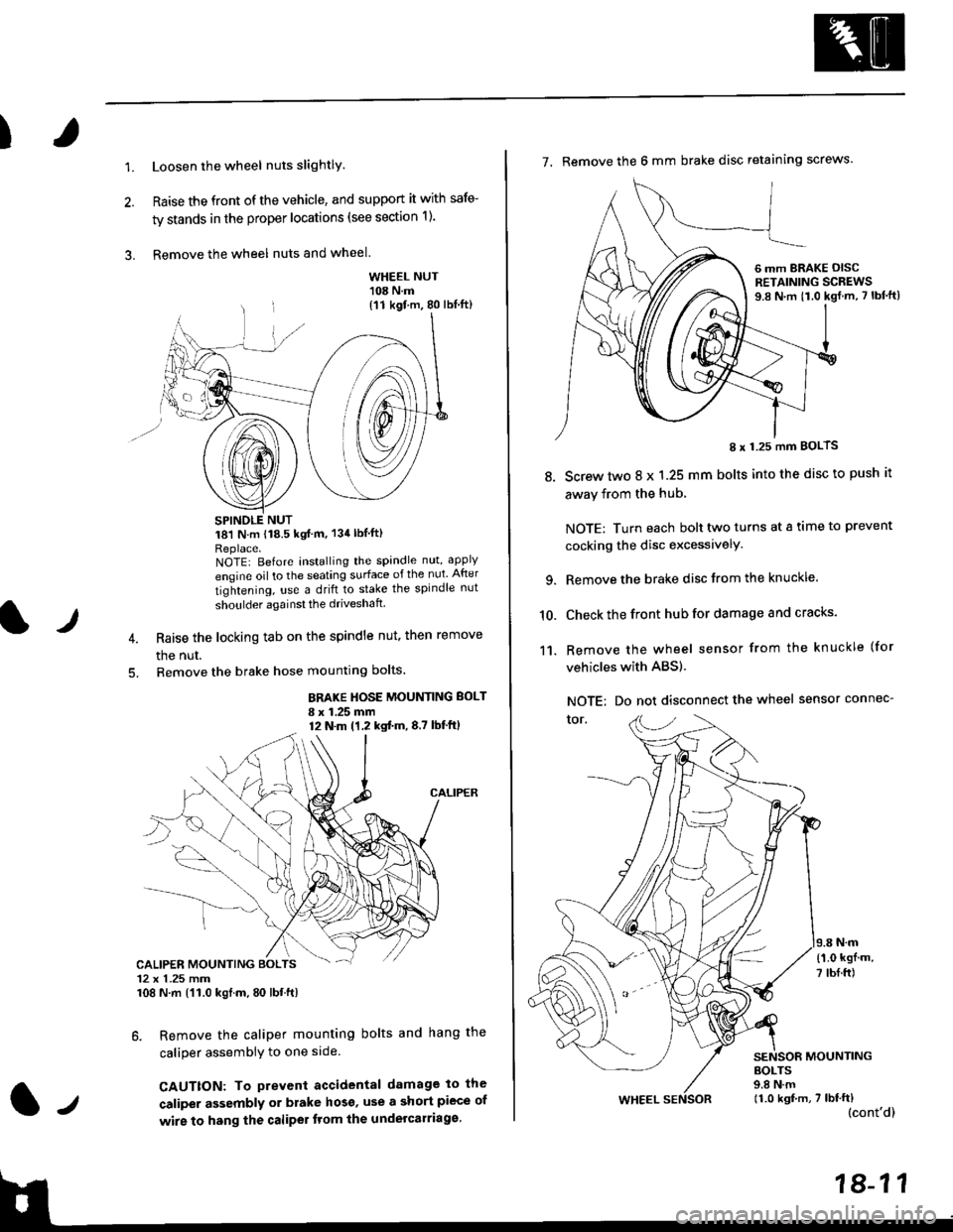
1.Loosen the wheel nuts slightlY.
Raise the front of the vehicle, and support it with safe-
ty stands in the proper locations (see section 1).
Remove the wheel nuts and wheel.3.
l)
WHEEL NUT'108 N.m
18'l N.m 118.5 kgf m, 134lblfti
Replace.NOTEI Before installing the spandle nut, apply
engine oil to the seating surface of the nut After
tightening, use a drift to stake the spindle nut
shoulder againsl the driveshaft
Raise the locking tab on the spindle nut, then remove
the nut.
Remove the brake hose mounting bolts.
BRAKE HOSE MOUNTING BOLT
I x 1.25 mm12 N.m (1,2 kgtm,8,7 lbf'ftl
6. Remove the caliper mounting bolts and hang the
caliper assembiy to one side
CAUTTON: To prevent accidental damage to the
caliper assembly or brake hoso' use a short piece of
wire to hang the caliPer tlom lhe undelcarriage.
{11 kgf m, 80 lbl.ft)
CALIPER MOUNTING BOLTS12 x 1.25 mm108 N.m {'11.0 kgtm, 80 lbt.ft)
7. Remove the 6 mm brake disc retaining screws.
8.
I x 1.25 mm BOLTS
Screw two 8 x 1.25 mm bolts into the disc to push it
away from the hub,
NOTE: Turn each bolt two turns at a tame to prevent
cocking the disc excessivelY.
Remove the brake disc from the knuckle.
Check the front hub for damage and cracks.
Remove the wheel sensor from the knuckle (for
vehicles with ABS).
NOTE: Do not disconnect the wheel sensor connec-
tor.
N.m
6 mm BRAKE OISCRETAINING SCREWS9.8 N.m t1.0 kgf.m, 7 lbf'ft)
{'1.0 kgf m,
7 tbf.ft)
10.
11.
MOUNTING
WHEEL
BOLTS9.8 N.m11.0 kgf,m, 7 lbf'ft)(cont'd)
Page 1137 of 2189

)
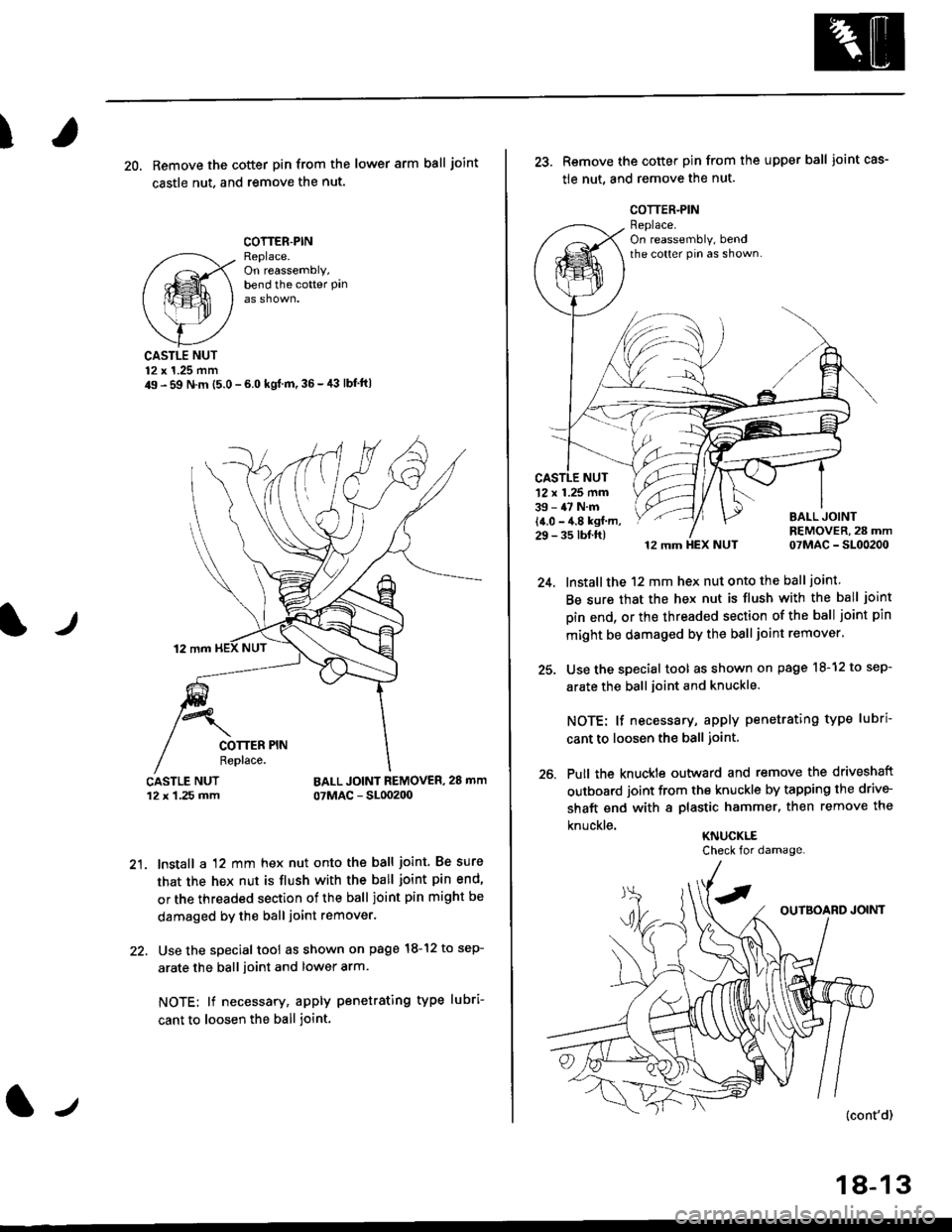
20, Remove the cotter pin from the lower arm ball joint
castle nut. and remove the nut.
COTTER.PINReplace.On reassembly,bend the cotter Pan
lr
CASTLE NUT12 x 1.25 mm49 - 59 N.m (5.0 - 6.0 kgl m,36-,13 lbf'ft|
BALL JOINT REMOVER, 28 mm
07MAC - SL00200
21. lnstall a 12 mm hex nut onto the ball joint. Be sure
that the hex nut is flush with the ball joint pin end'
or the threaded section of the ball joint pin might be
damaged by the ball joint remover.
22. Use the special tool as shown on page l8-12 to sep-
arate the ball ioint and lower arm.
NOTE; lf necessary, apply penetrating type lubri-
cant to loosen the ball joint.
lJ
18-13
25.
26.
Remove the cotter pin from the upper ball joint cas-
tle nut, and remove the nut.
12 mm HEX NUT 07MAC - SL00200
lnstall the 12 mm hex nut onto the ball joint
Be sure that the hex nut is flush with the ball joint
pin end, or the threaded section of the ball joint pin
mlght be damaged by the ball joint remover'
Use the special tool as shown on page l8-12 to sep-
arate the ball joint and knuckle.
NOTE: lf necessary, apply penetrating type lubri
cant to loosen the ball joint.
Putl the knuckte outward and remove the driveshaft
outboard joint from the knuckle by tapping the drive-
shaft end with a plastic hammer, then remove the
knuckle.KNUCKLE
'12 x 1.25 mm39 - 47 N.m
14.0 - 4.8 kgf m,29 - 35 tbf.ft)
Check for damage.
Page 1144 of 2189
Front Damper
Installation (cont'd)
2. Install the damper fork over the driveshaft and onto
the lower arm. Install the front damper into the
damper fork so the aligning tab is aligned with the
slot in the damper fork.
ALIGNING TAB
DAMPERPINCHEOLT10 x 1.25 mm43 N.m 14.4 kgf.m, 32 lbtftl12 x 1.25 mm64 N.m 16.5 kgl.m, 47 lbtftlReplace.
Loosely install the damper pinch bolt into the top ofthe damper fork.
Loosely install the damper fork bolt and a new self-locking nut into the bottom of the damper fork.
Raise the knuckle with a floor jack until the vehiclejust lifts off the safety stand.
@E The ftoor ilck must be sscuroty posi-
lionsd or personal iniury may r€€uh.
Tighten the damper pinch bolt.
Tighten the damper fork bolt and self-locking nut.
Tighten the flange nuts on top of the damper.
Install the brake hose mounts with the brake hose
mounting bolts.
Install the front wheel.
7.
8.
9.
10.
1a-20