Page 1047 of 2189
Driveshafts
17.
Reassembly (cont'dl
Unwind the boot band tool, and cut off the excess 5- 10 mm (0.2 - 0.4 in) from the clip.
5-10mm10.2 - 0.a inl
Secure the end of the boot band by tapping it downwith a hammer,
19. Installthe new set ring,
18.
Note these items after reassembly:. Make sure the band and clip does notanything and the band does not move.a Remove any grease remaining on thesurfaces.
interfere with
su rrou nding
16-14
Outboard Joint Sid.:
1. Wrap the splines with vinyl tape to prevent damageto the boot.
TPE tvDe:-. OUTBOARO BOOT ITPE)
BOOT BANDReplac€,
Rubber typ.:
Install the boot band and outboard boot, thenremove the vinyl tape. Take care not to damage theboot,
Install the stop ring into the driv€shaft groove.
DRIVESHAFT
>VINYL TAPE
VINYL TAPE
Page 1048 of 2189
J)
4. lnsert the driveshaft into the outboard joint until the
stop ring is close on the ioint.
DRIVESHAFT
To completely seat the outboard joint, pick up the
driveshaft and joint, and drop them from about 10
cm (4 to 5 inches) onto a hard surface. Do not use a
hammer as excessive force may damage the drive-
shaft.
16-15
J
6. Check the alignment of the paint mark with the out-
board joint end.
Pack the outboard joint with the joint grease includsd
in th€ new ioint boot set.
Gleaso quanlity
U.S., canada, and Brazil'Ploducod:
115 - 135 g {4.0 - 4.8 oz}
Japan-Producod:
161X, DOHC VTEC angino:
Rubbor boot: 90 - 100 g 13.2 - 3.5 oz)
TPE boot: 1tl6 - 115 I {3'7 - tl'l oz}
Excapt 1000 DOHC VTEC engine:
Rubbel boot: 70 - 80 g l.2.5 - 2.8 ozl
TPE boot: 95 - 105 g {3.4- 3.7 oz}
7.
DRIVESHAFT
(cont'd)
Page 1049 of 2189
Driveshafts
Reassembly lcont'd)
Installthe outboard boot and the boot bands.. lf the boot is the rubber type. go to step 13.. lf the boot is the TPE type, go to step 9.
Fit the boot ends onto the driveshaft and outboard
ioint.
10, Set the ear clamp band by threading the tab into theholes of the band.
EAR CLAMP BANDReolace.
8.
16-16
11. Close the ear portion of the band with a commer-cially available boot band Dincerc.
BOOT BAND PINCERSKENT-MOORE J,35910or eouivalent
Chsck the clearanca between the closed ear oonionof the band. lf the clesrance is not within the stan-
dard, close the ear portion of ths band further.
6.0 mm (0.24 in) MAX
3.0 mm 10.t2 inl MAX
EAR FOFNON
Page 1050 of 2189
I
13. Fit the boot ends onto the driveshaft and the
outboard joint
Fit the double loop boot bands onto the boot ends'
Pull up the slack in the band by hand'
Mark a position on the band 10 - 14 mm {0 4 - 0 6
in,) from the cliP.
14.
16.
CLIP
lrz
17. Thread the free end of the band through the nose
section of a commercially avaiiable boot band tool
KD-3191 or equivalent and into the slot on the wind-
ing mandrel.
BOOT BAND TOOL
lCommerciallY available)
KD-3191 or equivalent
MANDREL
Place a wrench on the winding mandrel of the boot
band tool, and tighten the band until the marked
spot on the band meets the edge of the clip'
Lift uo the boot band tool to bend the free end of
the band 90" to the clip Center punch the clip, then
fold over the remaining tail onto the clip
Mark spot.
18.
1q
(cont'd)
16-17
Page 1051 of 2189
Driveshafts
Reassembly (cont'dl
20. Unwind the boot band tool, and cut off the excessfree end of the band to leave a 5 - 10 mm (0.2 - 0.4in.) tail protruding from the clip.
21. Bend the band by tapping it down with a hammer.
NOTE: Maks sure the band and the clip does notinterfere with anything, and the band does notmov6. Remove any grease remaining in the sur-
rounding surtaces.
AANO END
16-18
INBOARD JOiIT
SET RII{G GR(X)VE
Installation
1, Install the new set ring onto the driveshaft groove.
Always use a new set ring whenever the driveshaftis being installed.
2. Install the outboard joint into the knuckte.
OUTBOARD JOINT
KNUCKI.E
Page 1052 of 2189

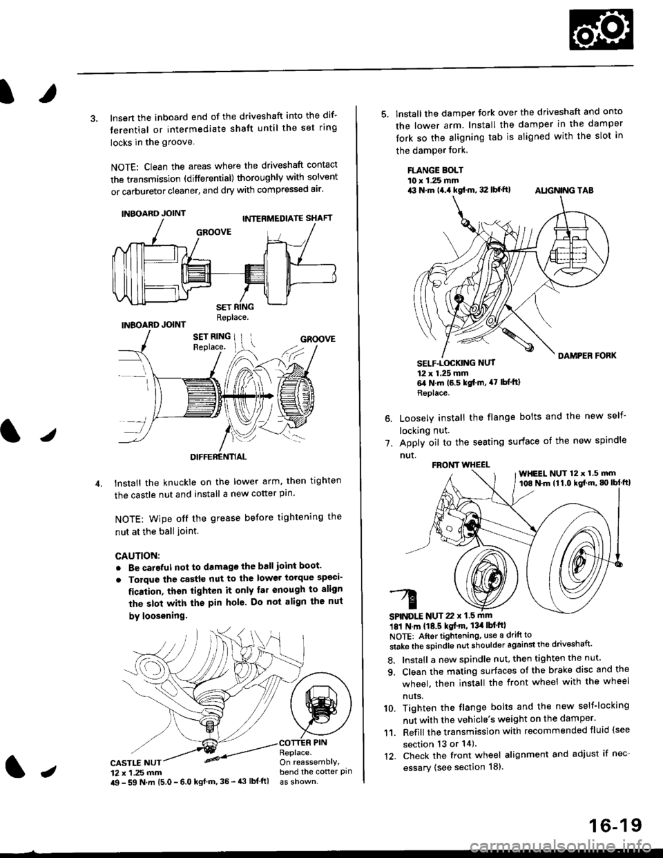
3. lnsert the inboard end of the driveshaft into the dif-
terential or intermediate shaft until the set ring
locks in the groove
NOTE: Clean the areas where the driveshaft contact
the transmission (differential) thoroughly with solvent
or carburetor cleaner, and dry with compressed air'
INBOARD JOINT
INBOARD JOINTReplace.
GROOVE
an
DIFFERENTIAL
lnstall the knuckie on the lower arm. then trghten
the castle nut and install a new cotter pin
NOTE: wipe off the grease before tightening the
nut at the ball ioint.
CAUTION:
. Be careful not to damago the ball ioint boot'
. Torque the castle nut to the lower torque sp€ci-
fication, thsn tighten it only far enough to align
the slot with th€ pin hol6. Do not align the nut
by loosening.
CASTLE NUT12 x 1 .25 mm
COTTER PINReplace.On reassemblY,bend the cotter pinJi$ - 59 N.m 15.0 - 6.0 kgl m,35 - 43 lbf ftl
16-19
5. lnstall the damper tork over the driveshaft and onto
the lower arm. Install the damper in the damper
fork so the aligning tab is aligned with the slot in
the damPer fork.
FLANGE BOLTl0 r 1.25 mmrit N.m t4.a kgf.m, 32 lbf.ft) AIIGN|NG TAB
1.
SELF-LOGKING NUT12 x 1.25 mm6,1N.m 16.5 kgi.m, a7 lbfftl
Replace.
Loosely install the flange bolts and the new self-
locking nut.
Apply oil to the seating surface of the new spindle
nut.
181 N m 118.5 kgt'm, 13il lbt'ftl
NOTE: Aftortightening, use a drift to
stake the spindle nut shoulder against the drivoshaft'
8. Install a new spindle nut, then tighten the nut'
9. Clean the mating surfaces ot the brake disc and the
wheel. then install the front wheel with the wheel
nuts.
10. Tighten the flange bolts and the new self-locking
nut with the vehicle's weight on the damper.
11. Refill the transmission with recommended fluid (see
section 13 or 14).'t2. Check the front wheel alignment and adjust if nec-
essary (see section 18),
FRONT WHEEL
SPINDLE NUT 22 x 1.5 mm
WHEEL NUT 12 x 1.5 mm108 N.m (11.0 kgl'm, g) lbl ftl
Page 1053 of 2189
Intermediate Shaft
Removal
Drain the transmission oil or fluid {see section 13 or
r 4).
Remove the left driveshaft (see page 16-3).
Remove the three dowel bolts.
OOWEL BOLTS'10 x 1.25 mm
Remove the intermediate shaft from the differential.
CAUTION: Hold the intermsdiate shaft horizontal
until it is clear of lhe dilterential to prevent damage
to the differential oil seal.
'1.
2.
3.
INTERMEDIATE SHAFT
16-20
Disassembly
NOTE: Be careful not to damage the metal rings on theintermediate shaft during disassembly.
1. Remove the set ring.
2. Remove the intermediate shaft outer seal from theDeaflng suppon.
3. Remove the external circlip,
Page 1134 of 2189

Front Suspension
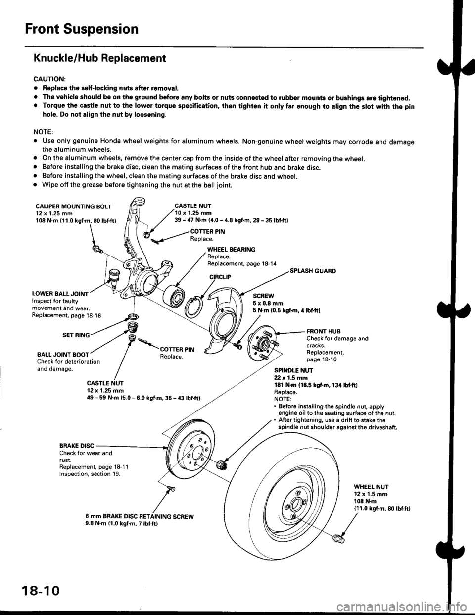
Knuckle/Hub Replacement
CAUTION:
. Replaco tho salf-locking nuts after romoval.
. The vehiclo should be on tho ground bsfore any bohs or nuls connected to rubber mounb or bushings are tightened.. Torqu€ th€ castle nut to the lowor torque specification, ihen tighton it only far enough to align th€ slot whh the pin
hole. Do not align the nut by loosening.
NOTE:
. Use only genuine Honda wheel weights for aluminum wheels. Non-genuine wheel weights may corrode and damagethe aluminum wheels.
. On the aluminum wheels, remove the center cap from the inside of the wheel after removing the wheel,. Before installing the brake disc, clean the mating surfaces of the front hub and brake disc,. Before installing the wheel, clean the mating surfaces of the brake disc and wheel.o Wipe off the grease before tightening the nut at the ball joint.
CALIPER MOUNTING BOLT12 x 1.25 mm108 N.m {11.0 kgl.m, 80lbf.ft)
LOWER BALL JOINTInspect for faultymovement and wear.
CASTLE NUT10 r 1.25 mm39 - ia7 N.m (4.0 - 4.8 kgf.m, 29 - 35 lbf,ftl
COTTER PINReplace.
WHEEL BEARINGReplace.Replacement, page 18-14
CIRCLIP
SCREW5x0.8mm5 N.m {0.5 ksl.m, 4 lbf.ftlReplacement, page 18-16
SET RING
BALL JOINT BOOT
FRONT HUBCheck for damage andcracks.Replacement,page 18-10Check for deteriorationand damage.
CASTLE NUT12 x 1.25 mm49 - 59 N.m l5.O - 6.0 kg{.m. 36 - /(} lbf,ftl
SPINDI.T ]{UT22 r 1.5 mmlEl N.m {18.5 kgf.rn, 13{ lbl.ttlReplace.NOTE:. Before instelling the spindle nut. apply6n9ine oilto th6 seating surface ofthe nut.. Atter tightening, uso a drift to stake thespindle nut should6r against the driveshaft.
BRAKE DISCCheck for wear andrust.Replacement, page 18-11lnspection, section 19.
WHEEL NUT12 x 1.5 mm'108 N.m1r1.0 kgf.m, 8lt lbf.ft)
6 mm BRAKE DISC RETAINING SCREW9.8 N.m 11.0 kgf.m, 7 lbtft)
18-10