1998 HONDA CIVIC Gear oil
[x] Cancel search: Gear oilPage 1103 of 2189
Steering Gearbox
)
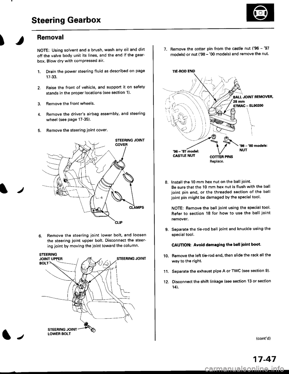
Removal
NOTE: Using solvent and a brush, wash any oil and dirt
off the valve body unit its lines. and the end if the gear-
box. Blow dry with comPressed air.
1. Drain the power steering fluid as described on page
2. Raise the front of vehicle, and support it on safety
stands in the proper locations (see section 11.
3, Remove the front wheels.
4. Remove the driver's airbag assembly, and steering
wheel (see page 17-35)
5. Bemove the steering joint cover.
6. Remove the steering joint lower bolt, and loosen
the steering joint upper bolt. Disconnect the steer-
ing joint by moving the ioint toward the column
tJ
17-47
TIE.ROD END
7. Remove the cotter pin from the castle nut {'96 -'97
models) or nut ('98 - '00 modslsl and remove the nut.
BALL JOINT REMOVER.28 mm07MAC - SLqI2|X)
'98 - '00 mod.b:NUT
8.
COTTER PINSRepl6ce.
lnstall the t0 mm hex nut on the ball joint.
Be sure that the 10 mm hex nut is flush with the ball
joint pin end, or the threaded section of the ball
joint pin might be damaged by the special tool.
NOTE: Remove the ball joint using the special tool.
Refer to section 18 for how to use ths ball joint
remover.
Seoarate the tie-rod ball joint and knuckle using the
specialtool.
CAUnON: Avoid damaging tho ball ioint boot.
Remove the left tie-rod end, then slide the rack all the
way to the right.
Separate the exhaust pipe A or TWC (see section 9).
Disconnect the shift linkage (see section 13 or section
14).
(cont'd)
9.
10.
11.
12.
Page 1110 of 2189
Steering Gearbox
Disassembly (cont'd)
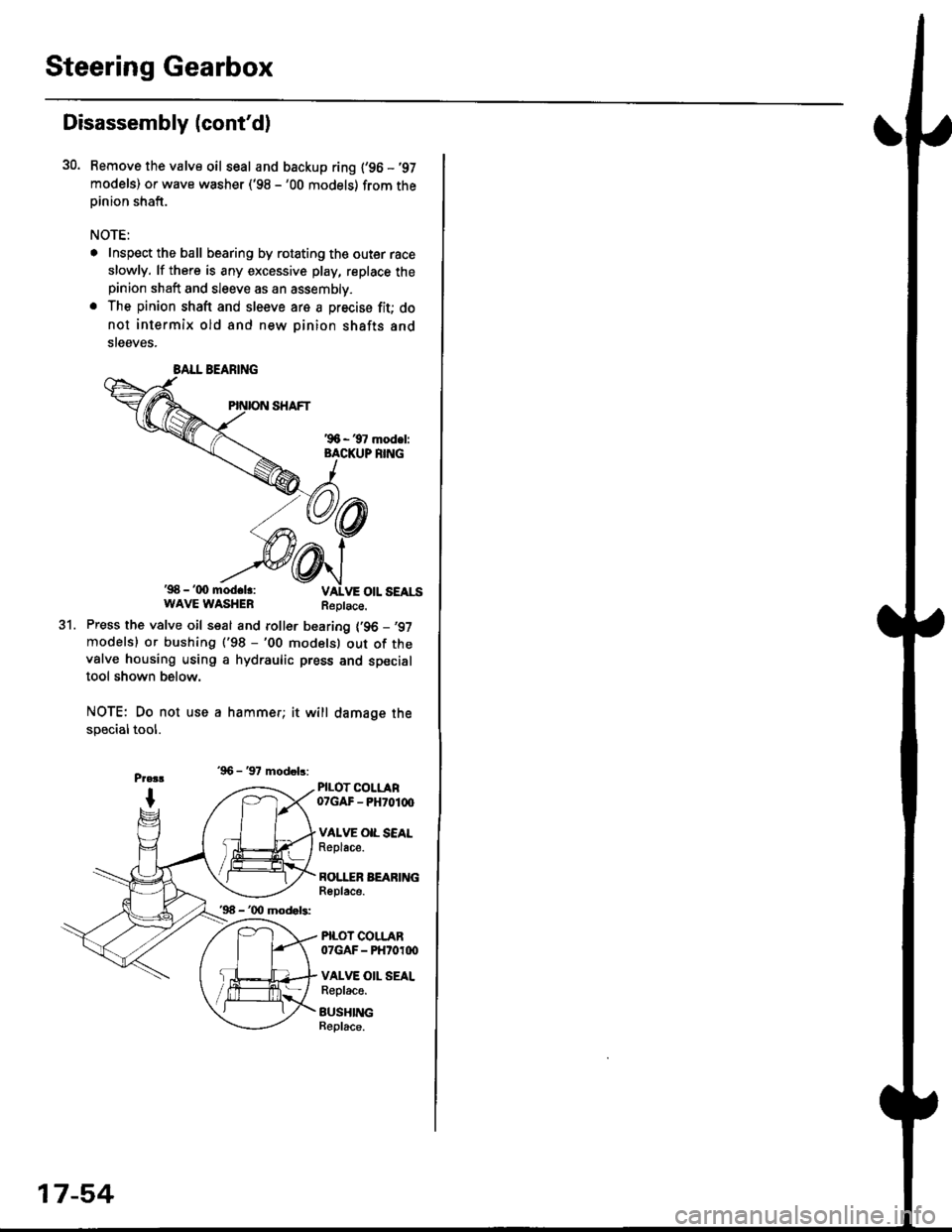
30. Bemove the valve oil seal and backup ring {'96 -'97
models) or wave washer ('98 -'00 models) from theoinion shaft.
NOTE:
. Inspect the ball bearing by rotating the outer race
slowly. lf there is any excessive play, replace thepinion shaft and sleeve as an assembly.
. The pinion shaft and sleeve are a precise fit; do
not intermix old and new pinion shafts and
steeves.
'98 - '(x) mod.lr:WAVE WASHERReplace.
31.Press the valve oil seal and roller bearing {'96 -,97
modelsl or bushing ('98 -'00 modelsl out of thevalve housing using a hydraulic press and specialtool shown below.
NOTE: Do not use a hammer; it will damage the
specialtool.
'96 - '97 modob:
PILOT COLLAR07GAF - PH70100
VAI.VE OIL SEALReplace.
BOI.I"ER BEARINGReplace.
PILOT COLLAR07GAF - PHtoroo
VALVE OII. SEALReplace.
BUSHINGBeplace.
BALL BEARING
'96 - '00 mod.b:
17-54
Page 1111 of 2189
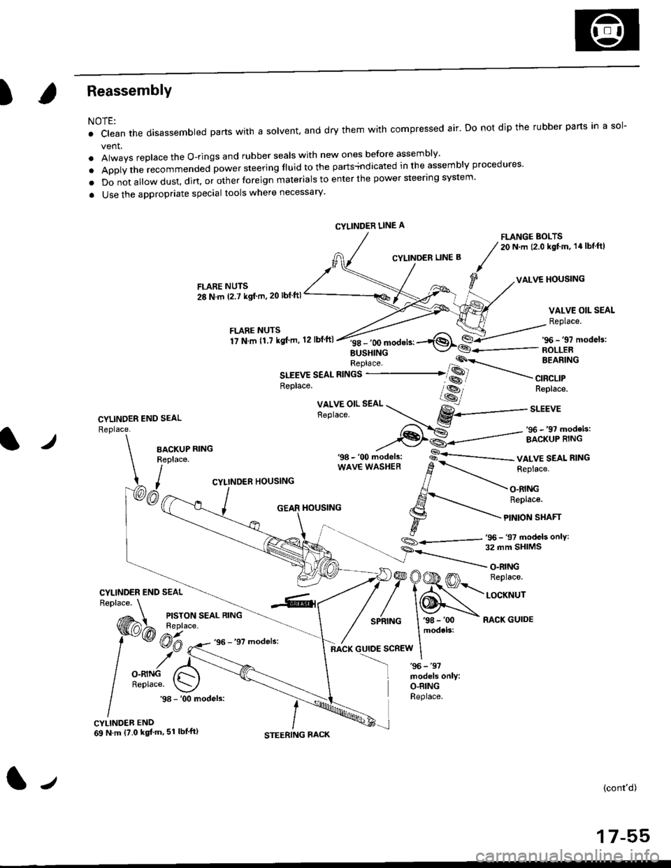
)Reassembly
NOTE:
. clean the disassembled parts wrth a solvent, and dry them with compressed air. Do not dip the rubber parts in a sol-
vent.
. Always replace the O-rings and rubber seals with new ones before assembly'
. Apply the recommended power steering fluid to the parts+ndicated in the assembly procedures'
o Do not a||ow dust, dirt, or other foreign materials to enter the power steering system.
a Use the appropriate special tools where necessary'
FLANGE BOLTS20 N.m (2.0 kgt'm, 14lbf ftl
CYLINDER LINE B
VALVE HOUSINGFLARE NUTS
28 N.m (2.7 ksf m,20 lbf ftl
VALVE OIL SEAL
Replace.
CYLINDER END SEAL
Replace.
f itllTllli".",'r'o,.n,ft
''*^'*-1$*€-/s6-,,mode,3:
EUSHINGReplace 'P'\-- BEARING
SLEEVE SEAL RINGS ..-------......�� SS
.----
",a"a,,
*---
--,
Replace. lss-, Replace.
Xll,Y5"l'.
"o. --r...- gY------..r.u,
,-f-..-S: _ ,96 _,9? models:
--€l€--------=- ircriip'ii.rt'-l./BACKUPReplace.
I,
wAvE wAsHER d
-.-.-r_ i"pru"".
CYLINDER HOUSING // -\-
, AJ - O.RING
/ ,S-'..- ReDtace.
_ j GEAR HouslNG l.g --'\-
\- t F
tonsrnrr
.,_- s
- 'oo ,,iod"t., -s-'--------- vALvE SEAL R'NG
S_.<---,tj- 97 models onlY:
CYLINDER END SEAL
)@OOD m n"prac".
/'\N,."._nrNG I '98 - 'oo - RACK GUIDE
models:
:scREw I
O.RINGReplace..98 - '00 models:
CYLINDER END69 N.m {?.0 kgt'm,51 lbl'ft)
(cont'd)
17-55
CYLINDER LINE A
tJ
Page 1112 of 2189
Steering Gearbox
Reassembly (cont'd)
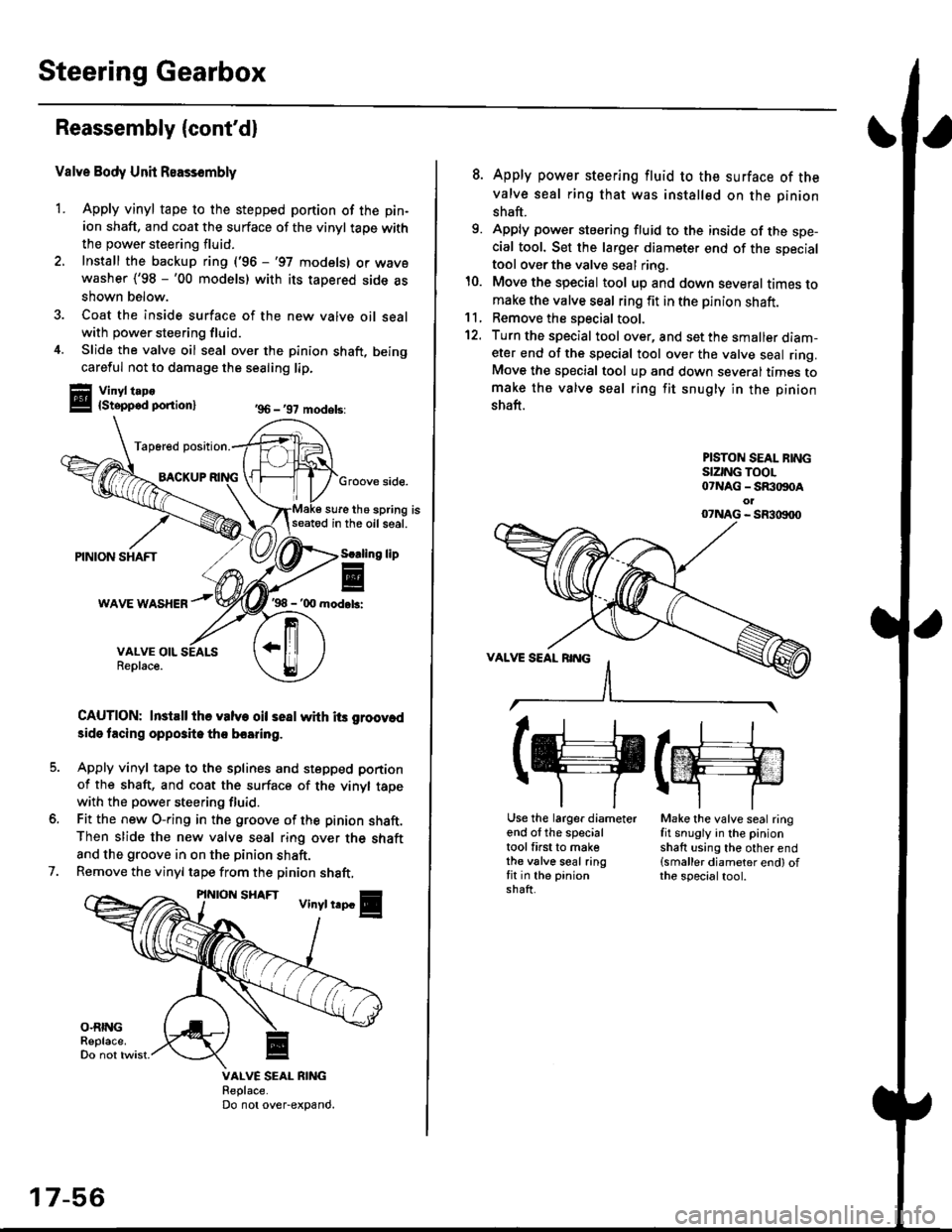
Valve Body Unit Reassembly
1. Apply vinyl tape to the stepped portion of the pin-
ion shaft, and coat the surface of the vinyl taoe with
the power steering fluid.
2. Install the backup ring ('96 -'97 models) or wavewasher ('98 -'00 models) with its tapered side as
shown below.
3. Coat the inside surface of the new valve oil sealwith power steering fluid.
4. Slide the valve oil seal over the pinion shaft, being
careful not to damage the sealing lip.
Vinyl t.po{Stepped ponion}
Tap6red position.
BACKUPGroove side.
sure the spring isseatod in the oil seal.
'98 - '00 mod.b:
CAUTION: InstEll ihe valve oil seal whh its groov.d
3ide tacing opposite tho boaring.
Apply vinyl tape to the splines and stepped portion
of the shaft, and coat the surface of the vinyl tapewith the power steering fluid.
Fit the new O-ring in the groove of the pinion shaft.Then slide the new valve seal ring over the shaft
and the groove in on the pinion shaft.
Remove the vinyl tape from the pinion shaft,
'96 - '97 models:
lip
7.
VALVE SEAL RIiIGReplace.Do not over-expand.
17-56
8. Apply power steering fluid to the surface of the
valve seal ring that was installed on the pinion
shaft.
9. Apply power steering fluid to the inside of the spe-cial tool. Set the larger diameter end of the specialtool over the valve seal ring.
10. Move the special tool up and down several times tomake the valve seal ring fit in the pinion shaft.11, Remove the soecial tool.
12. Turn the special tool over, and set the smaller diam-eter end of the special tool over the valve seal ring.Move the special tool up and down several times tomake the valve seal ring fit snugly in the pinion
shaft.
PISTON SEAL BINGSIZING TOOL07NAG - SR:togoAol07NAG - SR3|X)00
(g(m
Use the larger diameterend of the specialtool first to makethe valve seal ringfit in the pinionshaft.
Make the valve seal ringfit snugly in the pinionshaft using the other end(smaller diameter end) ofthe specialtool.
Page 1114 of 2189
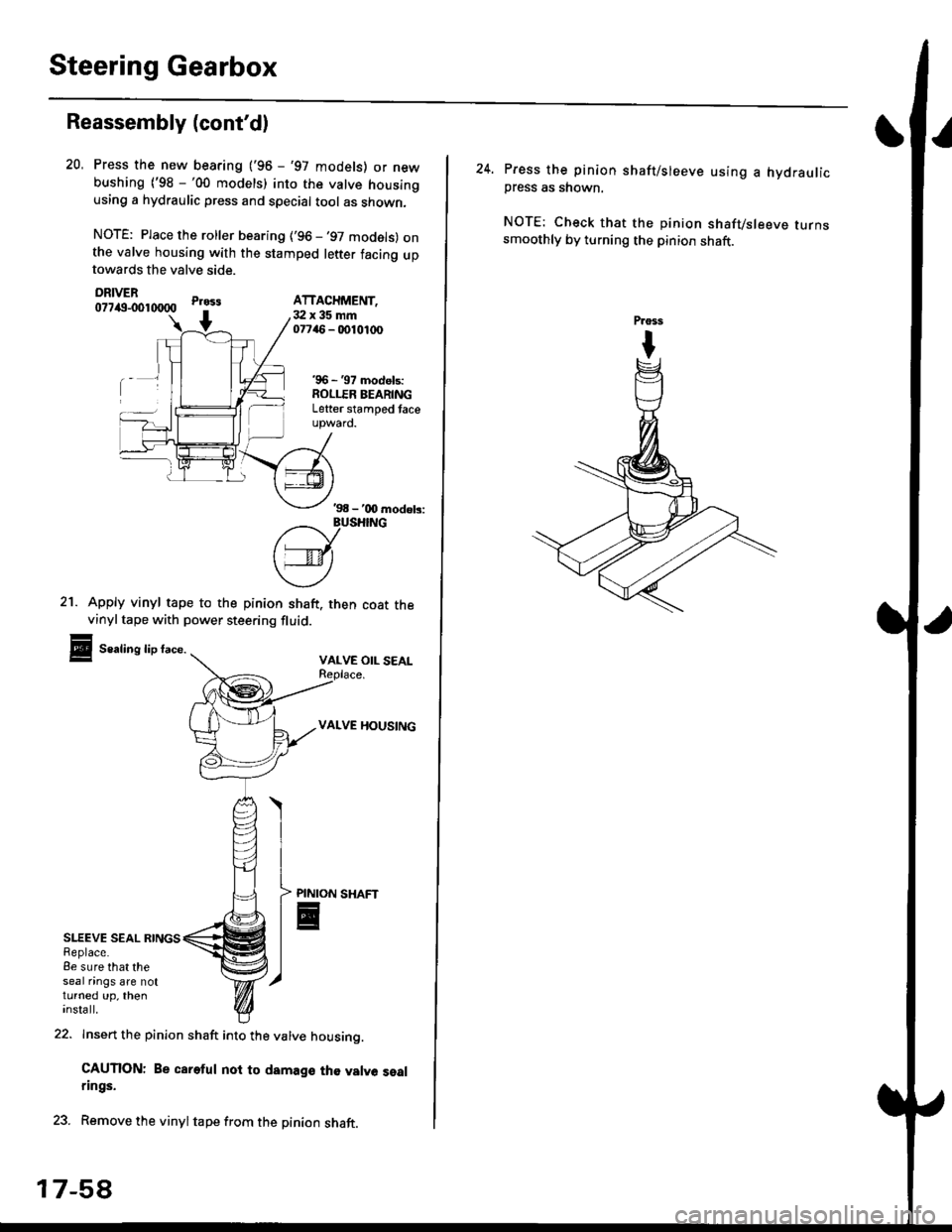
Steering Gearbox
Reassembly (cont'd)
SLEEVE SEAL RINGSReplace.8e sure that theseal nngs are notturned up, theninsta ll.
21. Apply vinyl tape to the pinion shaft. then coat thevinyltape with power steering fluid.
Sealing lip face.VALVE OIL SEAL
VALVE HOUSING
Press the new bearing ('96 - '97 models) or newbushing ('98 -'00 models) into the valve housingusing a hydraulic press and special tool as shown,
NOTE: Place the roller bearing ('96 -'97 models) onthe valve housing with the stamped letter facing uptowards the valve side.
DRIVER077itg-001tXlOO
22. Insert the pinion shaft into the valve housino.
CAUTION: Be careful noi to damage th€ valve sealrings.
23. Remove the vinyltape from the pinion shaft.
20.
Pr033
+3:Ix35mm07746 - 0010,t(x)
'96 - '97 models:ROLLER BEARINGLetter stamped taceupward.
ATTACHMENT,
'98 - '00 modob:
?/_vusHrNG
['---v-lt
\4)
PINION
E
17-5A
24. Press the pinion shaft/sleeve using a hydraulicpress as shown.
NOTE: Check that the pinion shafvsleeve turnssmoothly by turning the pinion shaft.
Page 1202 of 2189
L
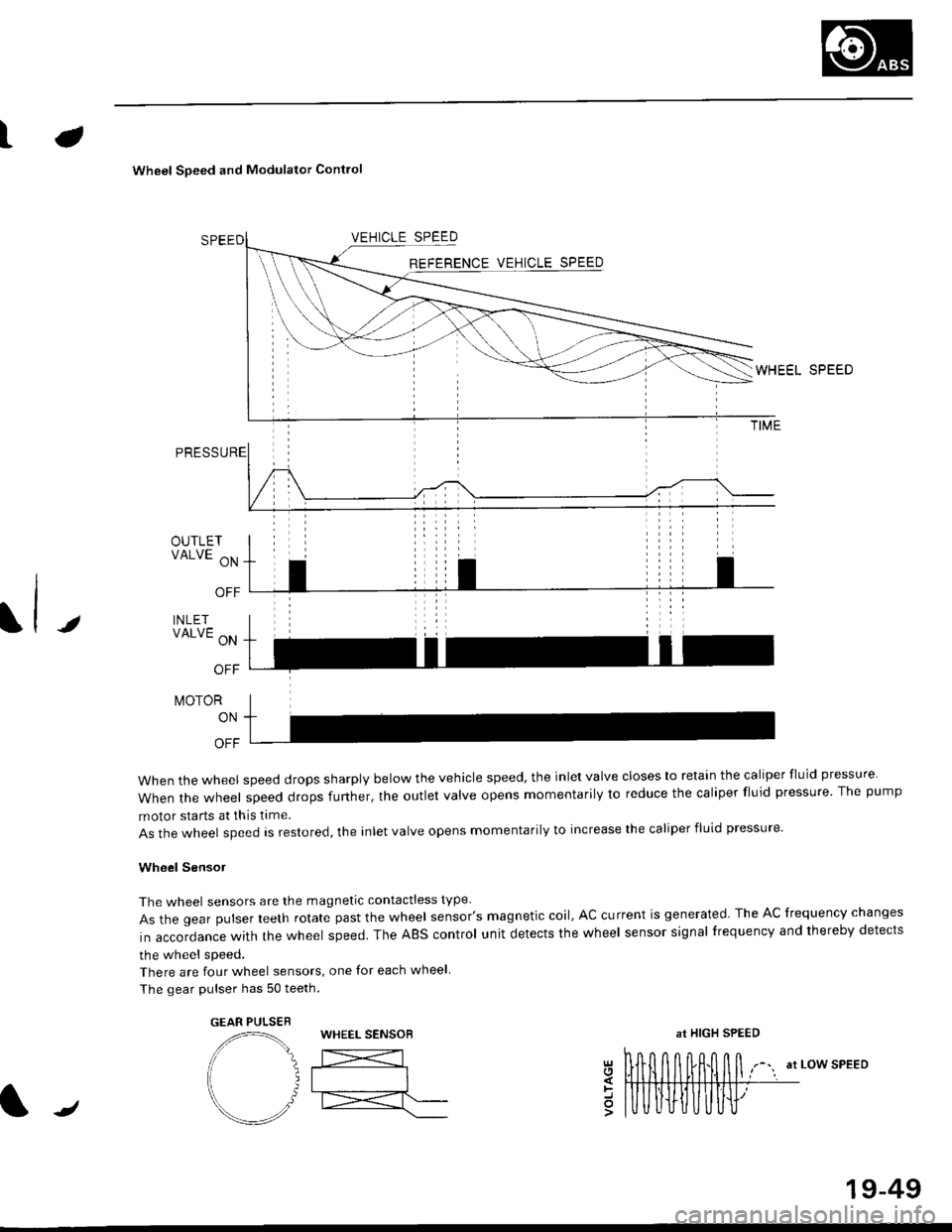
Wheel Soeed and Modulator Contlo
t
OUTLETVALVE ON
OFF
INLETVALVE ON
OFF
t\,40ToR
ON
OFF
when the wheel speed drops sharply below the vehicle speed, the inlet valve closes to retain the caliper fluid pressure
When the wheel speed drops further, the outlet valve opens momentarily to reduce the caliper fluid pressure. The pump
motor starts at this time.
As the wheel speed is restored, the inlet valve opens momentarily to increase the caliper fluid pressure.
Wheel SensoJ
The wheel sensors are the magnetic contactless type
As the gear pulser teeth rotate past the wheel sensor's magnetic coil, AC current is generated The AC frequency changes
in accordance with the wheel speed. The ABS control unit detects the wheel sensor signal frequency and thereby detects
the wheel speed.
There are four wheel sensors, one for each wheel
The gear pulser has 50 teeth.
EEL SPEED
at LOW SPEEDgl
=o
GEAR PULSEBWHEEL SENSOBat HIGH SPEED
/
19-49
Page 1486 of 2189

Connector ldentification and Wire Harness Routing
Engine Wire Harness lD16Y5, D16Y8 enginss): '96 - 98 models
Connector or
Torminal
Numbsr of
CavitissLocationConnects toNot€s
c 101c102c103c104c104c105c106c107c108c 109c110c111c112c113c114c115c116cl17c118c119c120cl21
c122c123cl23c124
c125
c127c12Ac129c130c131c132c 133c134c135
c136
c138c139c140c 141c142c 143c144cl44c145c'146cl47
10
1
22
14l4322l0I
2
2
2
2120
3l
14
14
1222
2
2
22
Left side of engine compartmentMiddle of engineMiddle of engineLeft side of engine companmentLeft side of engine compartmentMiddle of engineMiddle of engineMiddle of engineMiddle of engineMiddle of enginefvliddle of engineMiddle of engineMiddle of engineMiddle of engineMiddle of engineMiddle of engineMiddle of engineLeft side of engine compartmentMiddle of engineMiddle of engineMiddle of engineMiddle of engine
Middle of engineMiddle of engineMiddle of engineMiddle of engineMiddle of engineMiddle of engineMiddle of engineMiddle of engineMiddle of engineRight side of engine companmentBehind right kick panelUnder right side of dashUnder riOht side of dashUnder right side of dashUnder right side of dashUnder right side of dashUnder right side of dash
Under right side of dash
Under right side of dash
Middle of engineMiddle ot enginel iddle of engineMiddle of engineMiddle of ongineMiddle of engineLeft side of engine compartmentMiddle of engineMiddle of engineRight side of engine compartmentRight side of engine compartmentRight side of engine compartment
USACanada
Afi
USA
-' (A/r)
Main wire harness (C303)Crankshaft speed fluctuation (CKF) sensorEngine oil pressure switchAlternatorAlternatorNo. 'l fuel injectorNo. 2 fuel injectorNo.3 fuel injectorNo. 4 fuel injectorIAC valveThrottle position (TP) sensorl\4anifold absolute pressure (MAP) sensorIntake air temperature (lAT) sensorPower steering pressure {PSPI switchEVAP purge control solenoid valveJunction connectorJunction conn€ctorVehicle speed sensor {VSS}Countershaft speed sensorEngine coolant temp€rature (ECT) switch ADistributorEngine coolant temperature (ECT) sendingunrtEngine coolant temperature (ECT) sensorPrimary HO2S (sensor'l)Primary HO2S (sensor 1)Back-up light switchLock-up control solenoid valveSecondary HO2S (sensor 2)Mainshaft speed sensorLinear solgnoid valveShift control solsnoid valveStarter solenoidJunction connectorMain wire harnesE (C446)ECM/PCMPCMECMiPCMECM/PCMMain wire harness (C305)
Main wire harness (C305)
Main wire harness (C305)
Knock sensor (KS)IAC valveVTEC solenoid valveVTEC pressure switchEVAP control canister vent shut valveEGR control solenoid valveSecondary gear shaft speed sensorEGR valveEGR valveDrive pulley speed sensorSolenoid connector {CVT)Driven pulley speed sensor
*, (M/T)M/T*" INT\
*, tAtf)
NT:'96 model*,(A,/T):'97 - 98mooets
moqets
M/T
-1 (l,/T)*, (A,/T)-,(4,/T)*1 {M/T)*, (A,/T)*1 (CW)*, (A,T)
T101r102Left side of engine companmentRight side of engine companmentAlternatorUnder-hood fuse/relay boxG 101Middle of engineEngine ground, via engine wire harness
2
*1: Dl6Y5 engine*2: D16Y8 engine*3: D16Y5 (Ay'T), D16Y8 engines
3-16
Page 1488 of 2189
Gonnector ldentification and Wire Harness Routing
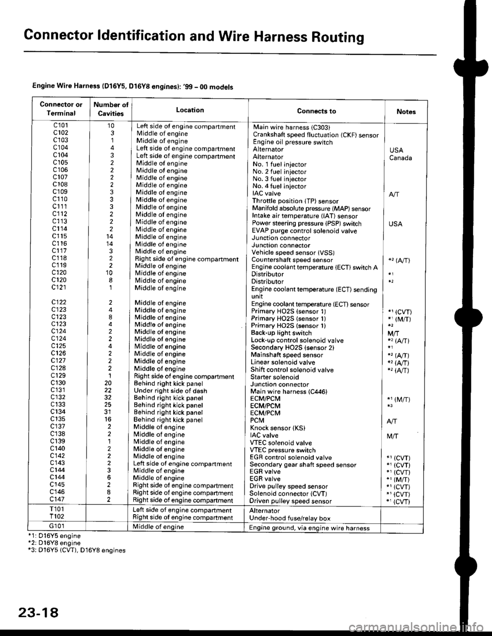
Engine Wire Harness (D16Y5, Dl6Yg engines): ,99 - 00 models
Connectot or
Terminal
Number ot
CavitiesLocationConn€cts toNotes
c'101cl02c103c104c 104c10s
c107c 108c'r09c110c111cl12c113cl14c l15c116cl17c118c119c120cl20c121
c122c123c123cl23cl24c124c125
c127c12Ac129c 130c131cl32c133c 134c135c137c138c 139c 140c142c143c144cl44c145c146c147
103,]
322223332221414322'10
8,l
2484224222120
32
2212223
282
No. 1 luel injector INo.2 fuel injectorNo.3 fuel injector ]No. 4 fuel injector iIAC valve I anThrottle position lTP) sensorManifold absolute pressure {MAP) sensor IIntake air temperature (lAT) sensor IPower steering pressure (PSP)switch USAEVAP purge control solenoid valve ]
Main wire harness 1C303)Crankshaft speed fluctuation (CKF) sensorEngine oil pressure switchAlternatorAlternator
Left side ot engine compartmentlvliddle of engineMiddle of engineLeft side ot engine compartmentLeft side of engine compartmentMiddle of engineMiddle ot engineMiddle of engineMiddle of engineMiddle oI engineMiddle of engineMiddle of engineMiddle of engineMiddle of engineNliddle of engineMiddle of engineMiddle of engineMiddle of engineRight side of engine compartmentMiddle of engineMiddle of engineN4iddle of engineMiddle of engine
Middle of engineMiddle ot engineMiddle ot engineMiddlo of engineMiddle of engineMiddle ot enginelrliddle of engineMiddle of engineMiddle oI engineMiddle ot engineRight side of engine compartmenlBehind right kick panelUnder right side of dashBehind right kick panelBehind right kick panelBehind righr kick panelBehind right kick panelMiddle ot engine[,liddle of engineN4iddle of engineMiddle of engineMiddle oI engineLeft side of engine compartmentMiddle of engineMiddle of engineRight side ol engine compartmentRight side of engine companmentRight side of engine compartment
USACanada
Junction connectorJUnct|On COnnectorVehicle speed sensor lVSS)Countershaft speed sensorEngine coolant temperature {ECT} switch ADistributorDistributorEngine coolant temperature (ECT) sendingunitEngine coolant temperature (ECT) sensorPrimary H02S (sensor 1)Primary HO2S (sensor 1)Primary HO2S lsensor 1)Back-up light switchLock'!p control solenoid valveSecondary HO2S (sensor 2)Mainshaft speed sensorLinear solenoid valveShift control solenoid valveStarter solenoidJunction connectorMain wire harness (C446)ECM/PCMECM/PCMECM/PCMPCtvtKnock sensor (KS)IAC valveVTEC solenoid valveVTEC pressure switchEGR control solenoid valveSecondary gear shaft speed sensorEGR valveEGR valveDrive pulley speed sensorSolenoid connector (CVT)Driven pulley speed sensor
*'� (A/TI
*1 (CVT)*, (M/T)
Mfia (A/Tl
" (A,/T)., (4,/r)-'� {AlrJ
*1 (M/T)
tvliT
*1 (CVT)*, (cvT)*' (cw)*1 (MiT)*1 {CVT)*1 {CVT)*, (cvr)
T101T102Left side of engine companmentRight side ot engine companmentAlternatorUnder'hood fuse/relay boxG 101Middle of englne IEngine ground, via engine wire harness*1: 016Y5*2: D16Y8*3: Dl6Y5
engineengine(CW), D16Y8 engines
23-14