1998 HONDA CIVIC Gear oil
[x] Cancel search: Gear oilPage 915 of 2189

Symptom-to-Component Chart
Electrical System -'96 - 98 Models
*: The DTC in parentheses is the code @ indicator light indicates when the Data Link Connector is connected to the HondaPGM Tester.
DTC*O Indicator
LightMILDetection ltemPage
P1790
(3)BlinksONThrottle position sensor14-242
P179'l
(4)BlinksONVehicle speed sensor14-243
P1705
(5)BlinksONAy'T gear position switch (short to groundl't 4-244
P1706
(6)OFFONA/T gear position switch {open)14-246
P0725
(11)BlinksONlgnition coil14-248
P1793
112lBlinksONManifold absolute pressure sensor14-249
P 1870(30)BlinksONShift control linear solenoid14-250
P'1873
(311BlinksONPH-PL control linear solenoid14-25'l
P1879(32)BlinksONStart clutch control linear sotenoid14-252
P1882BlinksONInhibitor solenoid14-253
P1885
(34)BlinksONDrive pulley speed sensor1l-Zb4
P1886(35)BlinksONDriven pulley speed sensor14-255
P1888
(36)BlinksONSecondary gear shaft speed sensor14-256
T to55
(37)BlinksONECM or TCM14-257
P1890
l42lBlinksONShift control system14-259
P1891
(43)BlinksONStart clutch control svstem14-260
14-23a
Page 945 of 2189
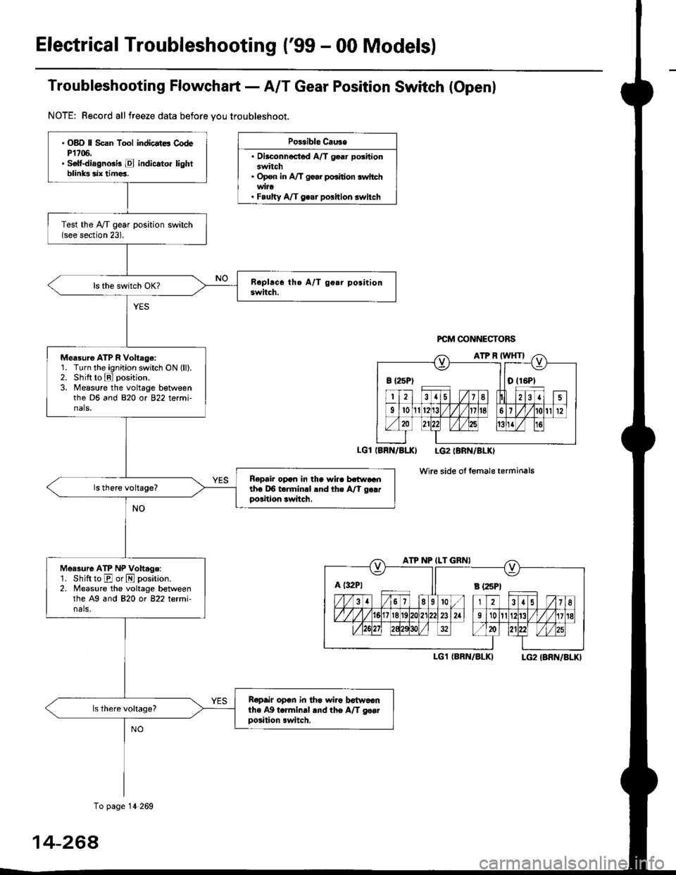
Electrical Troubleshooting {'99 - 00 Models)
Troubfeshooting Flowchaft- AIT Gear Position Switch (Openl
NOTE: Record allfreeze data before vou troubleshoot.
Po$ible Cau3e
. Oilconnected A/T goar positionswitch. Op€n in A/T go.r po.ition switchwi?o. Faulty A/T gear polition switch
PCM @NNECTORS
(BRN/BI.XI LG2IBRN/BLKI
wire side of fomale terminals
I-G1 (BRN/BLKILG2 {BRN/BLK)
B {25P) I tO (16P1
ATP NP ILT GRNI
A t:r2Pt Il s tzspt
. OBD ll Scan Tool indicstE CodeP1706.. Selt-diagnGi! E indicato. lightblinks six tim€a.
Test the IVT gear position switch(see section 23).
Measu.e ATP R Voltage:1. Turn the ignition switch ON (ll).2. Shift to E position.
3. Measure the voltage betweenthe D6 and 820 or 822 termi-nals,
Ropair opcn in the wi.. hr.raGnth6 DO torminrl lnd the A/t g..rposition awitch.
Measure ATP NP Vohage:'1. Shift to E or N position.2. Measure the voltage betweenthe A9 and 820 ot 822 letmi-nals,
Ropair op6n in th€ wiro b€{woanthe Ag t.rminal and the A/T go..position .witch.
To page 14 269
14-264
Page 988 of 2189
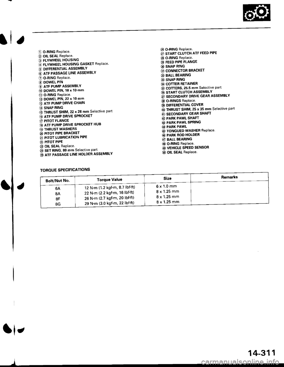
C O-RING Replace.
e) OIL SEAL RePlace.' FLYWHEEL HOUSING
O flVWneel }|OUSttttG GASKET Replace
6 DIFFERENTTALASSEMELY
@ lrr plsslce uruE ASSEMBLY
O O-RING Replace
@ DOWEL PIN
€) ATF PUMP ASSEMBLY(O DowEL PlN, 18 x 10 mm
O O-RING Replace.o DowEL PlN, 22 x 10 mm
lrr puup oRve cxltttt
iA SNAP RING
f3 fxaUst St|t|l, zz t 28 mm Selective part
Gt lrr punp ontve spaocxer
O PITOT FLANGE
ito nTF purrap ontve SPRoGKET HUB
(O THRUST WASHERS
@ PITOT PIPE BRACKET
O PITOT LUBRICATION PIPE
@ PITOT PIPEt3 OIL SEAL Replace.
Oa SEt AtitC, SO mm Selective Part
o3 lrr passlce ltnE HoLOER ASSEMBLY
6) o-RING Replace.
€) START CLUTCH ATF FEED PIPE
CO O-RING Replace.
€I FEEO PIPE FLANGE
@ SNAP RING
O' CONNECTOR BRACKET
@ BALL BEARING
6} SNAP RING64 COTTER RETAINER6D CoTTERS,25.5 mm selective Part6t stlnt cLutcH asseMsLv
@ secoruomv ontvE GEAR ASSEMBLY
@ o-RINGS Replace
6) DIFFERENTIAL COVER
rO ttaUSr SntU, zs t 35 mm Selective part
@ SECONDARY GEAR SHAFT
@ PARK PAWL SHAFT
@ PARK PAWL SPRING.1i PARK PAWL
@ TONGUED WASHER REPIACE,
@ PARK ROO HOLDER
@ BALL BEARING
@ o-RING Replace.
@ VEHICLE SPEED SENSOR
@ OIL SEAL Replace.
ft,
)
TOROUE SPECIFICATIONS
6x1.0mm
8 x 1.25 mm
8 x 1.25 mm
8 x 1.25 mm
12 N.m (1.2 kgnm,8.7 lbf'ft)
22 N.m (2.2 kgf'm. 16lbf'ft)
26 N.m (2.7 kgf'm, 20 lbf'ft)
29 N.m {3.0 kgf'm, 22 lbift)
14-311
Page 1061 of 2189
Steering Gearbox
l.r
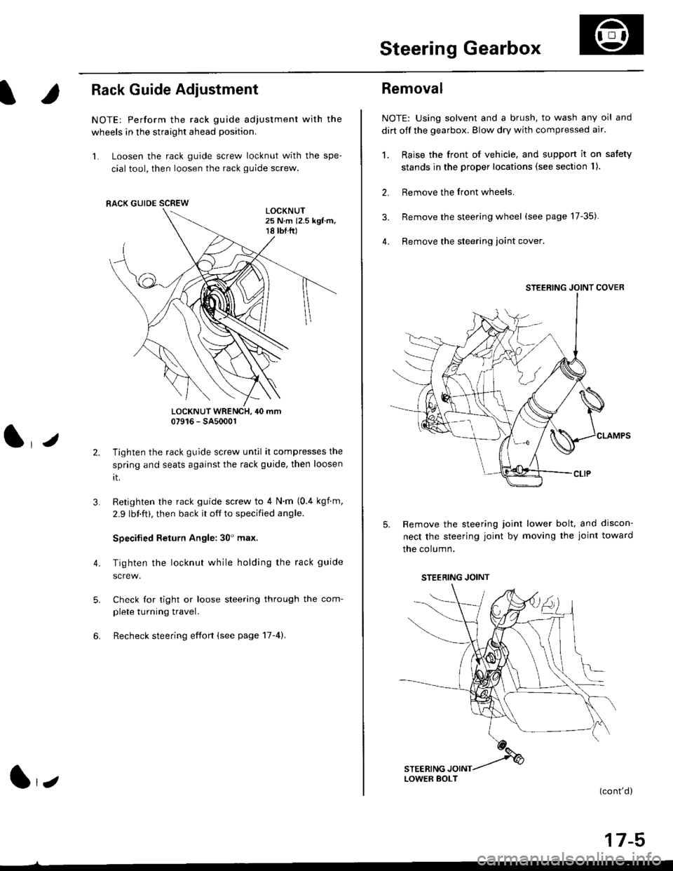
Rack Guide Adjustment
NOTE: Perform the rack guide adjustment with the
wheels in the straight ahead position.
1. Loosen the rack guide screw locknut with the spe-
cial tool, then loosen the rack guide screw.
LOCKNUT WRENCH, 40 mm07916 - SA5000r
Tighten the rack guide screw until it compresses the
spring and seats against the rack guide, then loosen
rt.
Retighten the rack guide screw to 4 N'm (0.4 kgf m,
2.9 lbf.ft), then back it off to specified angle.
Specilied Return Angle: 30' max.
Tighten the locknut while holding the rack guide
Check for tight or loose steering through the com-
plete turning travel.
Recheck steering effort (see page 17-4).
4.
RACK GUIDE SCREW
l,z
Removal
NOTE: Using solvent and a brush, to wash any oil and
dirt off the gearbox. Blow dry with compressed air.
1. Raise the front of vehicle, and support it on satety
stands in the proper locations (see section I ).
2. Remove the front wheels.
3. Remove the steering wheel (see page 17-35).
4. Remove the steering loint cover
Remove the steering joint lower bolt, and discon-
nect the steering joint by moving the joint toward
the column.
(cont'd)
17-5
STEERING JOINT COVER
LOWER BOLT
STEERING JOINT
Page 1074 of 2189
System Description
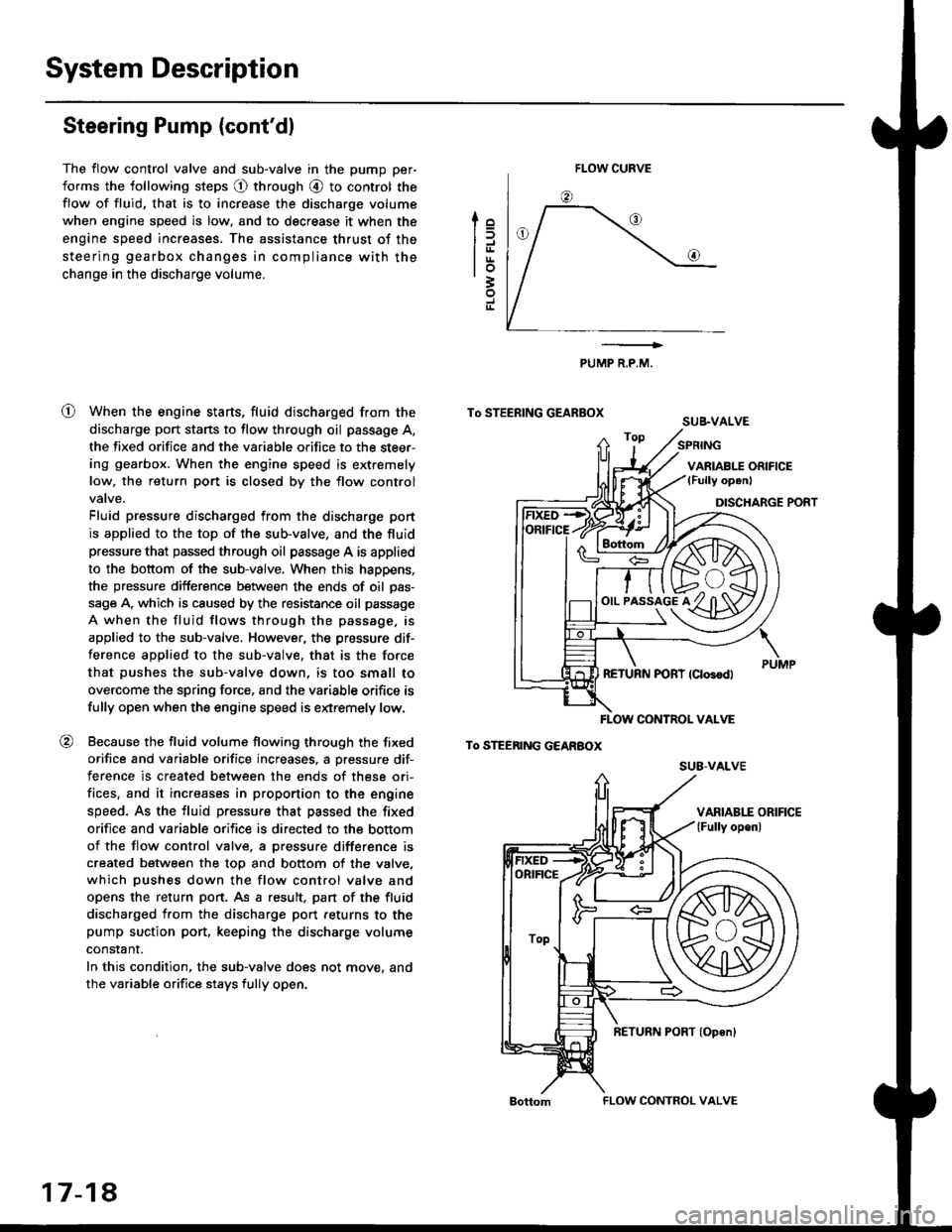
Steering Pump (cont'dl
The flow control valve and sub-valve in the pump per-
forms the following steps @ through @ to control the
flow of fluid, that is to increase the discharge volume
when engine speed is low, and to decrease it when the
engine speed increases. The assistance thrust of the
steering gearbox changes in compliance with the
change in the discharge volume.
When the engine starts, fluid discharged from the
discharge port starts to flow through oil passage A,
the fixed orifice and the variable orifice to the steer-
ing gearbox. When the engine speed is extremely
low, the return port is closed by the flow control
Fluid pressure discharged from the discharge port
is applied to the top of the sub-valve, and the fluid
pressure that passed through oil passage A is applied
to the bottom of the sub-valve. When this happens,
the pressure difference between the ends of oil pas-
sage A, which is caused by the resistance oil passage
A when the fluid flows through the passage. is
applied to the sub-valve, However, the pressure dif-
ference applied to the sub-valve. that is the force
that pushes the sub-valve down, is too small to
overcome the spring force, and the variable orifice is
fully open when the engine speed is extremely low.
Because the fluid volume flowing through the fixed
orifice and variable orifice increases, a pressure dif-
terence is created between the ends of these ori-
fices, and it increases in proportion to the engine
speed. As the fluid pressure that passed the fixed
orifice and variable orifice is directed to the bottom
of the flow control valve. a pressure difference is
created between the top and bottom of the valve,
which pushes down the flow control valve and
opens the return port. As a result, pan of the fluid
discharged from the discharge port feturns to the
pump suction port, keeping the discharge volume
constant.
In this condition, the sub-valve does not move. and
the variable orifice stays fully open.
lo
trrtrrlo3
J
o
PUMP R.P.M.
To STEERING GEARBOXSUB.VALVE
To STEEnING GEARBOX
FLOW CURVE
!rs+/f/ffih\
o,,-i^"l^tKzYt)91y ul3Yl
FLOW CONTNOL VALVE
su8-vALvE
ORIFICE
ToP
17-18
FLOW CONTROL VALVE
Page 1075 of 2189
t
To STEERING GEARBOX
To STEERING GEAREOx
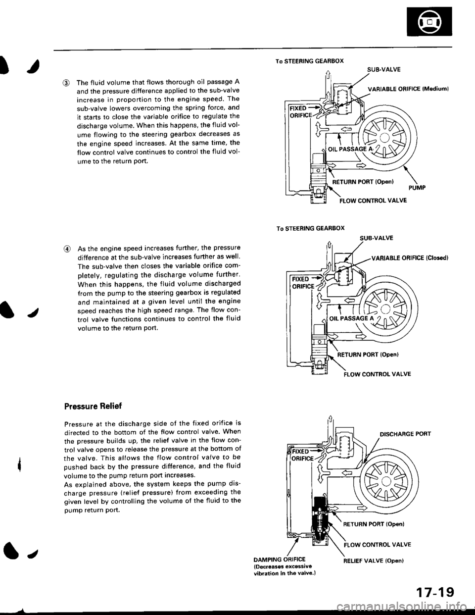
@ The fluid volume that flows thorough oil passage A
and the pressure djfference applied to the sub-valve
increase in proportion to the engine speed. The
sub-valve lowers overcoming the spring force, and
it stans to close the variable orifice to regulate the
discharge volume, When this happens, the fluid vol-
ume flowing to the steering gearbox decreases as
the engine speed increases. At the same time, the
flow control valve continues to control the fluid vol-
ume to the return Port,
@ As the engine speed increases funher, the pressure
difference at the sub-valve increases further as well.
The sub-valve then closes the variable orifice com-
pletely, regulating the discharge volume further.
When this happens, the fluid volume discharged
from the pump to the steering gearbox is regulated
and maintained at a given level until the engine
speed reaches the high speed range The flow con-
trol valve functions continues to control the fluid
volume to the return Port.
Pressure Relief
Pressure at the discharge side of the fixed orifice is
directed to the bottom of the flow control valve. When
the pressure builds up, the relief valve in the flow con-
trol valve opens to release the pressure at the bottom of
the valve. This allows the flow control valve to be
pushed back by the pressure difference, and the fluid
volume to the pump return port increases.
As explained above. the system keeps the pump dis-
charge pressure (relief pressure) from exceeding the
given level by controlling the volume of the fluid to the
pump relurn pon,
1.,DAMPING ORIFICE{Docreases excessiv€vibration in the valv6.)
17-19
)
RELIEF VALVE {Opan)
SUB.VALVE
FLOW CONTROL VALVE
/F ft>..\
'-€/K\A/A
o'.'to"5lo'#2"n af11\D7
FLOW CONTROL VALVE
Page 1081 of 2189
/
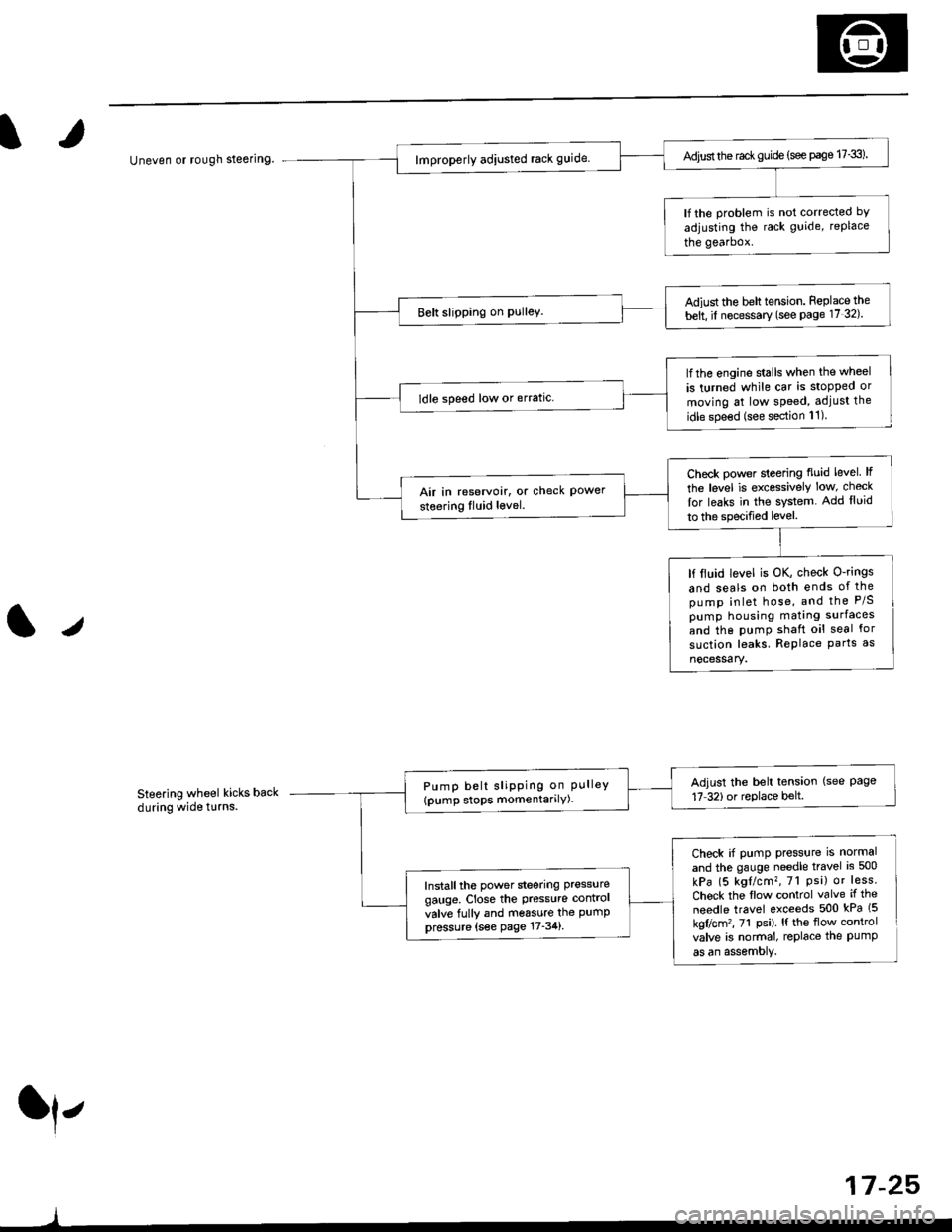
Uneven or rough steering
Steering wheel kicks back
during wide t!rns.
ll,
)
Adjust the rac* guide (see page 17-3).
lf the problem is not corrected bY
adjusting the rack guide, replace
the gearbox.
Adiust the belt tension. Feplace the
belt, il necessary (see Page 17 32).
lfthe engine stalls when the wheel
is turned while car is stopped or
moving at low speed, adjust the
idle spe€d (see section 11)
ldle speed low or erratic.
Check power sleering fluid level lf
the level is excessively low, check
lor leaks in the system. Add lluid
to the specified level.
Air in reservoir, or check Powersteering Iluid level.
lf ltuid level is OK, check O-rings
and seals on both ends of thepump inlet hose, and the P/Spump housing mating surfaces
and the pumP shaft oil seal for
suction leaks. RePlace Parts as
nocessary.
Adjust the belt tension (see Page17 32)or replace belt.Pump belt sliPPing on PLrlleY(pump stops momentarilY)
Check if pump press{rre is normal
and the gauge needle travel is 500
kPa (5 kgl/cm?, 7l Psi) or less.
Chock the flow control valve if the
needle travel exceeds 500 kPa (5
kgflcm'�, 71 Psi). l{ the flow control
valve is normal, replace the PumPas an assemoly.
Install the power steering pressure
gauge, Close the Pressure contrcl
valve fully and m6ssure the PumPpressure {s€e page 17-34}.
17 -25,
Page 1084 of 2189
Troubleshooting
Fluid Leaks
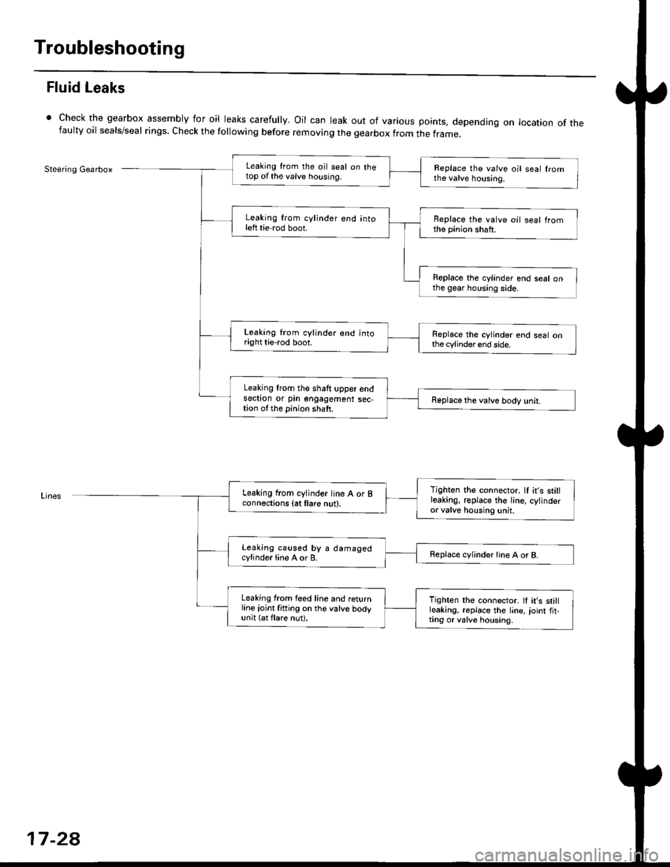
Check the gearbox assembly for oil leaks carefully. Oil can leak out of various points. depending on location of thefaulty oil seals/seal rings. Check the following before removing the gearbox from the frame_
Steering GearboxLeaking from the oil seal on thetop of the valve housing.Replace the valve oil seal fromthe valve housing.
Leaking from cylinder end intoleft tie rod boot.Replace the valve oil seal tromthe pinion shaft.
Replace the cylinder end seal onthe gear housing side.
Leaking lrom cylinder end intoright tie-rod boot.Replace the cylinder end seal onthe cylinder end side.
Leaking lrom the shaft upper endsectron or pin engagement sec,tion ol the pinion shaft.Replace the valve body unit.
Tighten the connector. lf it's stillleakinO, replace the Iine, cylinderor valve housing unit.
Leaking from cylinder line A or Bconnections {at tlare nut}.
Leaking caused by a damagedcylinde.line A or B.Replace cvljnder line A or B.
Leaking from feed line and returnline ioint fitting on the valve bodyunit (at flare nut).
Tighten the connector. ll it's stillleaking, replace the line,,oint fit,ting or valv6 housing.
17-2a