Page 771 of 2189

Troubleshooting Flowchart - Countershaft Speed Sensor
NOTE: Record all freeze data before you troubleshoot
Po$iblo Cause
. Loos€ or fsulty conneclionbetween the PCM and vehicle
hainoss' Disconnectod countersh.ft
spoed senaof connoctor. Short or opgn in counteBhaft
3Deed aensor wire. Faulty counloEhaft 3p€ed sen'
soa
COUNTERSHAFf SPEED
SENSOR CONNESTOR
Terminal side oI male terminals
FCM CONNECTOR D I16PI
rconl c
1+93
NC IBLUI
. OBD ll Scan Tool indicat6 Code
PO720.. Self-diagnosis E indicator light
blinks nin6times.
Check the countershaft sPeed
sensor installation, and check it
lor damage.
ls the countershaft speed sensor
installed properly, and not dam-
aged?
Reinstall or replace and rechock.
Measurg Counlershatt SPeed
Sgn3ol R6istance at tho Son3ol
Connector:1. Disconnect the 2P connector
from the countershaft sPeed
sensor.2, Measuro countershaft sPeed
sensor resistanca at the sensor
connector.
ls the resistance 400 - 600 O?
Chcck CounteEh.tt SPeed Sen'
sor lor a Short Circuit:1. Disconnect the D {16P) con
nector trom the PCM.2. Check lor continuity between
body ground and the D10 ter_
minal and D16 terminal indi-
vid!ally.
R6oai. short in tl|€ wi.6a bstwa€n
the D10 and D16 t.rminali end
tho countdthatt rP€od senaor.
To page 14 94
Wire side of temale terminals
Page 779 of 2189

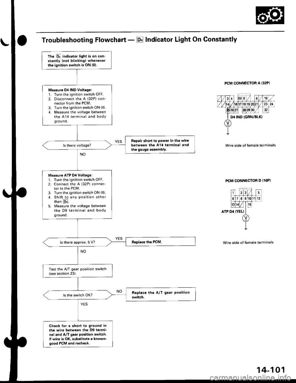
Troubleshooting Flowchart - El Indicator Light On Constantly
PCM CONNECTOR A I32P)
Wire side of lemale terrnanals
PCM CONNECTOR D {16P)
ATP D'
25
61e 11(12
t{Iro
(YELI
Wire side of female terminals
The Dll indicator lighi is on con-stantly {not blinking) whenever
the ignition switch is ON (lll.
Moasure D4 IND Voltage:1. Turn the ignition switch OFF.2. Disconnect the A {32P} con-nector from the PCM.3. Turn the ignition switch ON (ll).
4. Measure the voltage betweenthe A14 terminal and bodyground.
Repsir short to power in the wire
between the A14 torminal andthe gauge assembly.
Measure ATP D4 Voltagel1. Turn the ignition switch OFF.2. Connect the A (32P) connector to the PCM.3. Turn the ignition switch ON (ll).
4. Shitt to any position othertha n [ql.5. Measure the voltage betweenthe D9 terminal and bodyground.
ls there approx. 5 V?
Test the A/T gear position switch(see section 23).
Check Ior a short to ground inthe wire betweon the D9 termi-
nal and A/T gear position switch.It wire is OK, substitute a known-good PCM and recheck.
Page 912 of 2189

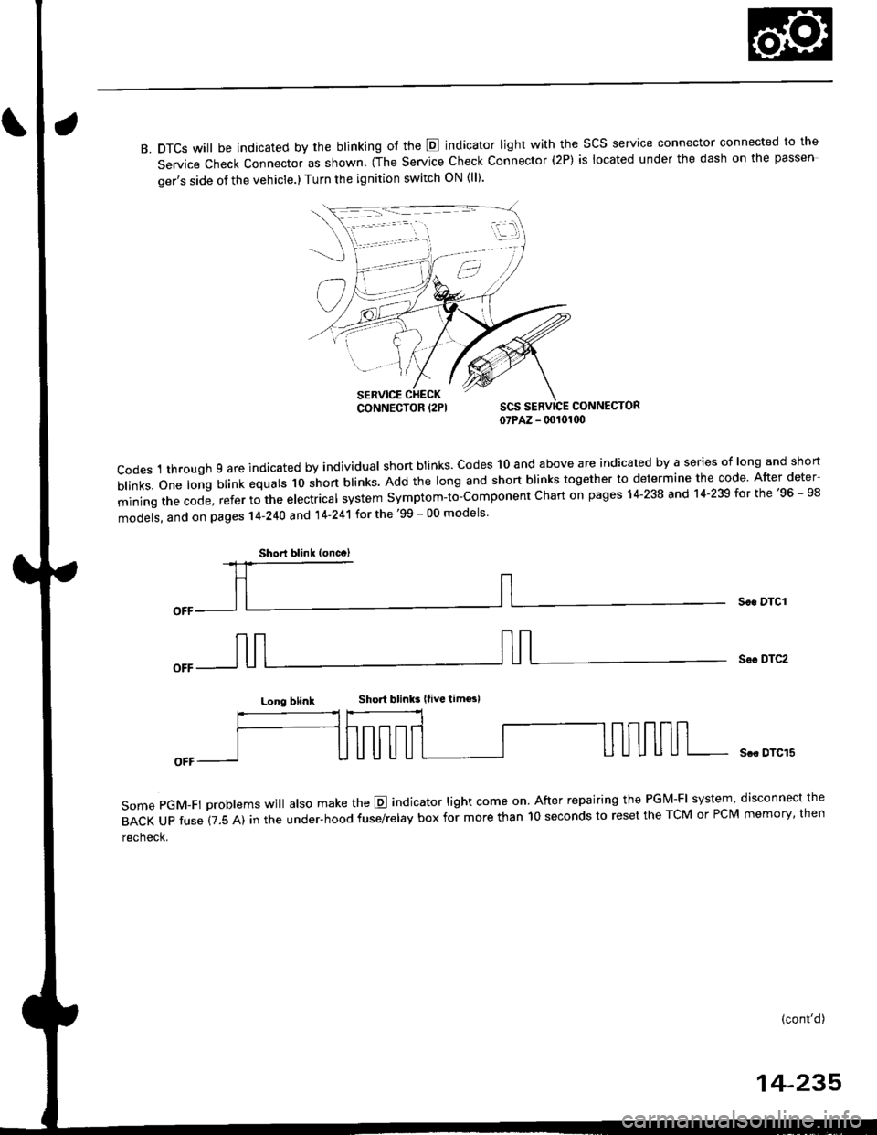
B. DTCS will be indicated by the blinking of the E indicator light with the SCS service connector connected to the
Service Check Connector as shown. (The Service Check Connector (2P) is located under the dash on the passen
ger's side of the vehicle.) Turn the ignition switch ON (ll).
CONNECTOR07PAZ - 00101(x)
codes 1 through 9 are indicated by individual shon btinks. codes 10 and above are indicated by a series of long and short
b|inks.one|ongblinkequa|sloshortb|inks.Addthe|ongandshortb|inkstogethertodeterminethecode.Afterdeter
miningthecode,refertothee|ectrica|systemsymptom-to-componentchartonpagesl4-238and14.239forthe,96_98
models, and on pages 14-240 and 14'241 for the '99 - 00 models
Soc DTCI
Sor DTC2
Long blinkShort blinks |tive tim€sl
some pGM-Ft problems wi
atso make the E indicator light come on. After repairing the PGM-FI system, disconnect the
BACKUPfuse(7.5A)intheUnder.hoodfuse/re|ayboxformorethanl0secondstoresettheTcMorPcMmemory,then
recheck.
Scc DTCI5
(cont'd)
14-235
iii:j
,,,/
CONNECTOR {2PI
Shorl blink (oncc)
Page 915 of 2189

Symptom-to-Component Chart
Electrical System -'96 - 98 Models
*: The DTC in parentheses is the code @ indicator light indicates when the Data Link Connector is connected to the HondaPGM Tester.
DTC*O Indicator
LightMILDetection ltemPage
P1790
(3)BlinksONThrottle position sensor14-242
P179'l
(4)BlinksONVehicle speed sensor14-243
P1705
(5)BlinksONAy'T gear position switch (short to groundl't 4-244
P1706
(6)OFFONA/T gear position switch {open)14-246
P0725
(11)BlinksONlgnition coil14-248
P1793
112lBlinksONManifold absolute pressure sensor14-249
P 1870(30)BlinksONShift control linear solenoid14-250
P'1873
(311BlinksONPH-PL control linear solenoid14-25'l
P1879(32)BlinksONStart clutch control linear sotenoid14-252
P1882BlinksONInhibitor solenoid14-253
P1885
(34)BlinksONDrive pulley speed sensor1l-Zb4
P1886(35)BlinksONDriven pulley speed sensor14-255
P1888
(36)BlinksONSecondary gear shaft speed sensor14-256
T to55
(37)BlinksONECM or TCM14-257
P1890
l42lBlinksONShift control system14-259
P1891
(43)BlinksONStart clutch control svstem14-260
14-23a
Page 916 of 2189
lf the self-diagnostic E indicator light does not blink, perform an inspection according to the table below.
SymptomInspectionRef. page
E indicator light does not come on for two seconds after ignition switch
is first turn on (ll).14-262
E indicator light is on constantly (not blinking) whenever the ignition
switch is on (ll).14-264
NOTE:
. lf a customer described the symptom for code P1706 (6), it will be necessary to recreate the symptom by test driving,
then recheck the DTC.
. Sometime the E indicator light and the Malfunction Indicator lamp (MlL) may come on simultaneously. lf so, repair the
pGM-Fl system according to the DTc, then reset the memory by removing the BACK uP fuse in the under-hood
fuse/relay box for more than 10 seconds. Drive the vehicle for several minutes at a speed over 30 mph (50 km/h)' then
recheck the DTC.
14-239
Page 917 of 2189
Symptom-to-Com ponent Chart
Electrical System -'99 - 00 Models
r: The DTc in parentheses is the code E indicator light indicates when the Data Link connector is connected to the HondaPGM Tester.
DTCTE Indicatot
LighrMILDetostion ltemPage
P1705
(5)ElinksONA,/T gear position switch (short to grouno,14-265
P1706
(6)OFFONA"/T gear position switch (open)14-26€
P1870
(30)BlinksONShift control linear solenoid14-271
P1873
(31)BlinksONPH-PL control linear solenoid14-213
P1879
t32lBlinksONStan clutch control linear solenoid
Inhibitor solenoid
14-215
P1882(33)BlinksON't 4-277
P1885
(34)BlinksONDrive pulley speed sensol't 4-279
P1886
(35)BlinksONDriven pulley speed sensor14-281
P1888
(36)BlinksONSecondary gear shaft speed sensor
Shift control system
14-283
P1890
\421BlinksON14-245
P1891
(43)BlinksONStart clutch control system14-286
14-240
Page 918 of 2189
lf the self-diagnostic E indicator light does not blink. perform an inspection according to the table below.
SYmPtom
IDI indicator light does not come on for two seconds after ignition switch
is first turned ON (ll).
lE1 indicator light is on constantly (not blinking) whenever the ignition
switch is ON { ll).
InspectionRef. page
14-284
14-290
NOTE:
. lf a customer described the symptom for code Pl706 (6), it will be necessary to recreate the symptom by test driving,
then recheck the DTC.
. iometimes, tfre E indicator light and the Malfunction Indicator lamp (MlL) may come on simultaneously lf so, repair
the PGM-Fl system accordrng to the DTC, then reset the memory by removing the BACK UP RADIO fuse in the under-
hood fuse/relay box for more than 10 seconds. Drive the car for several minutes at a speed over 30 mph {50 km/h)' then
recheck the DTC.
14-241
Page 919 of 2189

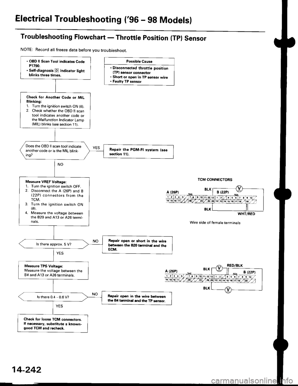
Electrical Troubleshooting ('96 - 98 Modelsl
Troubleshooting Flowchart - Throttle position (Tpl Sensor
Possible Cause
. Disconnected throftle position(TPl 3ensor connoctol. Short or open in TP sensor wire. Fauhy TP sensol
TCM CONNECTORS
Wire s;de of female terminals
. OBO ll Scan Tool indic.tes CodeP1790.. Self-diagnosis E indicator lightblinks three times.
Check lor Anothar Code or MILBlinking:1. Turn the ignition switch ON 1 ).2. Check whether the OBD ll scantool indicates another code orthe Malfunction Indicator Lamp(MlL) blinks (see secrion 11).
Does the OBD ll scan tool indicateanothercode oristhe MIL blink-ing?
Repair the PGM-FI systom (3eesection 111.
Measure VREF Voltage:1. Turn the ignition switch OFF.2. Disconnect the A (26P) and B{22P} connectors lrom theTCM.3. Turn the ignition switch ON{fl).4. Measure the voltage bet\iveenthe 820 and A13 or 426 termi-nals,
Repair open or short in thc wireb,stween the Bao tcrminal rnd theECM.
ls lhere approx. 5 V?
Measure TPS Voltago:Measure the voltage between theB4 and A13 or 426 terminals.
Repail open in the wire tr€tweonthe Erl t6.minal ind the TP sen3o..ls there 0.4 - 0.6 V?
Check for loose TCM connectors.lf necessary, substitute a known-good TCM and r6check.
NOTE: Record all freeze data before you troubleshoot.
BLK
WHT/RED
A {26P1