1998 HONDA CIVIC Control arm
[x] Cancel search: Control armPage 809 of 2189

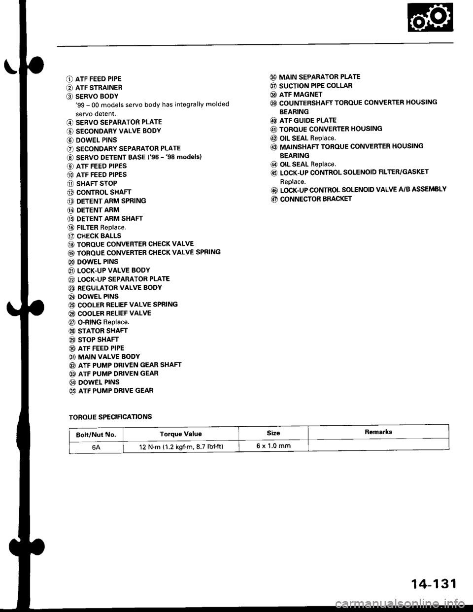
O ATF FEED PIPE
O ATF STRAINER
O SERVO BODY'99 - 00 models servo body has integrally molded
servo detent.
@ SERVO SEPARATOR PLATE
(' SECONDARY VALVE BODY
@ DOWEL P|NS
O SECONDARY SEPARATOR PLATE
@ SERVO DETENT BASE ('�96 -'98 models)
O ATF FEED PIPES
(D ATF FEED PIPES
O SHAFT STOP
@ CONTROL SHAFT
€D DETENT ARM SPRING
@ DETENT ARM
(9 DETENT ARM SHAFT
@ FILTER Replace.
(? CHECK BALLS
@ TOROUE CONVERTER CHECK VALVE
@ TOROUE CONVERTER CHECK VALVE SPRING
@ DOWEL PINS
@ LOCK.UP VALVE BODY
@ LOCK-UP SEPARATOR PLATE
@ REGULATOR VALVE BODY
@} DOWEL PINS
@ COOLER RELIEF VALVE SPRING
@ COOLER RELIEF VALVE
@ O-RING Replace.
@ STATOR SHAFT
@ STOP SHAFT
@ ATF FEED PIPE
@ MAIN VALVE BODY
@ ATF PUMP DRIVEN GEAR SHAFT
@ ATF PUMP DRIVEN GEAR
@ DOWEL PINS
65) ATF PUMP DRIVE GEAR
@ MAIN SEPARATOR PLATE
@ SUCTION PIPE COLLAR
@ ATF MAGNET
@ COUNTERSHAFT TOROUE CONVERTER HOUSING
BEARING
@ ATF GUIDE PLATE
@ ToRoUE CONVERTER HOUSING
@ OIL SEAL Replace.
@ MAINSHAFT TOROUE CONVERTER HOUSING
BEARING
@) olL SEAL Replace.
@ LOCK-UP CONTROL SOLENOID FILTER/GASKET
Reolace.
@ LOCK-UP CONIROL SOLENOID VALVE A/B ASSEMELY
@ CONNECTOR BRACKET
TOROUE SPECIFICANONS
Bolt/Nut No.Torque ValugSiz€Remarkg
12 N.m (1.2 kgf.m,8.7 lbnft)6x1,0mm
14-131
Page 814 of 2189

Torque Converter Housing/Valve Body
Removal
ATF FEEO PIP€
LOCK-UP VALVEBODY
PIN
6x1.0mm
LOCK-UP SEPARATORPLATE
REGULATORVALVE SODY
DOWEL PIN
COOLER RELIEF VAL
SERVO DETENTSTRAINER
SERVO EODY
SEPARATON
BASE
ATF FEEDPIPES
CONTROLSHAFT
DETENTARM SHAFT
DETENTARM
ATF FEED PIPE
6x1.0mm5 Eolts6x1.0mm3 Eolts
MAIN VALBODY
ATF PUMP
DRIVEN
VALVE BODY
PINGEAR SHAFT
ATF PUMP
MAIN SEPARAPLATE
SECONDARYSEPARATOR PLATE
NOTE: The illustration shows the '96 - 98 models, the '99 - 00 models do not have the servo detent base; the servo detentis integral with the servo body.
L
14-136
Page 815 of 2189

NOTE;
. Clean all parts thoroughly in solvent or carburetor
cleaner, and dry with compressed air.
. Blow out all passages.
. When removing the valve body, replace the O-ring.
l, Remove the ATF feed pipes from the servo body,
secondary valve body and main valve body.
For'96 - 98 models: Remove the ATF strainer and
servo detent base (two bolts).
For'99 - 00 models: Remove the ATF strainer (one
bolt).
Remove the servo body and servo separator plate
{'96 - 98 models: seven bolts,'99 - 00 models: eight
bolts).
Remove the secondary valve body, shaft stop and
secondary separator plate (three bolts).
Remove the lock-up valve body and separator plate
{seven bolts).
Remove the regulator valve body (one boltl.
Remove the stator shaft and stop shaft.
Remove the detent spring from the detent arm. then
remove the control shaft from the to.que converter
housing.
Remove the detent arm and detent arm shaft from
the main valve body.
Remove the main valve body (five bolts).
NOTE: Do not let the eight check balls fall outofthe
main valve body when removing the main valve
body.
Remove the ATF pump driven gear shaft, then remove
the ATF pump gears.
Remove the main separator plate and two dowel
pins.
7.
't'1.
10.
12.
14.
13. CIean the inlet opening of the ATF strainer thor-
oughly with compressed air. then check that it is in
good condition, and the inlet opening is not clogged.
INLET OPENING
Test the filter by pouring clean ATF fluid through
the inlet opening. Beplace the ATF strainer if it is
clogged or damaged.
NOTE: The ATF str8iner can be reused if it is not
clogged.
14-137
Page 855 of 2189

1.Install the ATF magnet and suction pipe collar in the
torque converter housing. if necessary.
lnstall the main seDarator plate and the two dowel
pins on the torque converter housang.
Install the ATF pump drive gear, ATF pump driven
gear and ATF pump driven gear shaft on the torque
converter housing.
NOTE; Install the ATF pump driven gear with its
grooved and chamfered side tacing down.
ATF PUMP
ATF PUMP DRIVENGEAR SHAFT
ATF PUMPDRIVEN GEAR
Grooved and chamferedside taces separalorplate.MAIN SEPARATORPLATE
4.Loosely install the main valve body with five bolts.
Make sure the ATF pump drive gear rotates smoothly
in the normal operating direction and the ATF pump
driven gear shaft moves smoothly in the axial and
normal operating directions.
Install the secondary valve body, separator plate
and two dowel pins on the main valve body.
NOTE: Do not installthe bolts.
6. Install the control shaft in the housing with the con-
trol shaft and manual valve together.
7. lnstall the detent arm and arm shaft in the main
valve body, then hook the detent arm spring to the
detent arm,
SERVO SEPARATOR PLATE
DETENT
MANUAL VALVE
DETENT ARM SPRING
15.
14-177
a
10.
11.
Install the servo body and separator plate on the
secondary valve body ('95 - 98 models: seven bolts.'99 - 00 models: eight boltsl.
For '96 - 98 models: Install the servo detent base
and the ATF strainer (two boltsl.
For'99 - 00 models: Install the ATF strainer (one
bolt).
Tighten the five bolts on the main valve body to 12
N.m ('1.2 kgf.m,8.7 lbf.ft).
Make sure the ATF pump drive gear and ATF pump
driven gear shaft move smoothlY'
lf the ATF pump drive gsar and ATF pump driven
gear shaft do not move freely, loosen ths five bolts
on the main valve body, and disassemble the valve
bodies.
Realign the ATF pump driven gear shaft and reassem-
ble the valve bodies, then retighten the bolts to the
specified torque,
CAUTION: Fsilule to align tho ATF pump driven
goar shaft corr.ctly will rscuh in a s€ized ATF pump
drive goar or ATF pump d ven gear shaft.
Install the stator shaft and stop shaft.
Install the bolts and the shaft stop on the secondary
valve body, then tighten the bolts (three boltsl.
Install the torque converter check valve, cooler relief
valve and valve springs in the regulator valve body.
then install the regulator valve body on the main
valve bodv (one bolt).
Install the lock-up valve body on the regulator valve
bodv (seven bolts).
Install the ATF feed pipes in the main valve bodY,
the three ATF feed pipes in the secondary valve and
the four ATF feed pipes in the servo body. (cont'dl
12.
't 3.
14.
PUMP
Page 863 of 2189

16. Install a new set ring on the end of each driveshaft'
17. Installthe right and left driveshafts (see ssction 16)
CAUTION: Whil6 installing the driveshafE in the
diffarential, be surs not lo allow du3t and othor for-
eign particl€s to enler into the transmission.
NOTE:
. Clean the areas where the driveshafts contact the
transmission (differential) thoroughly with sol-
vent or carburetor cleaner, and dry with com-
pressed air.
. Turn the right and left steering knuckle fully out-
ward, and slide each driveshaft into the differen-
tial until you feel its set ring clip engage the side
gear.
18. Install the damper fork, then install the rightand left
ball joints to the each lower arm with the castle nuts
and new cotter Plns.
DAMPER PINCH BOLT
10 x 1 .25 mma3 N.m l4.ia kgf.m,
32 tbl.ftl
4l
COTTERReplace.SELF.LOCKING NUT
12 x 1.25 mm
6il N.m t6.5 kgf'm, il7 lbf ftl
Replace.
19. Install the splash shield.
{5.0 - 6.0 kgf m, 36 - iB lbf'ft|
CASTLE NUT12 x 1,25 mm49 - 59 N.m
20. Connect the mainshaft speed sensor, the linear sole-
noid and the shift control solenoid connectors.
SHIFT CONTROL SOLENOIO LINEAR SOITNO|o
CONNECTOR CONNECTOR
6 r 1.0 mrn12 N.m (1.219f.m,
E.7 lbf.frl
CONNECTOR
21. Connect the countershaft speed sensor and the vehi-
cle speed sensor (VSS) connectors.
VEHICI..E SPEED
SENSOR CONNECTOR
COUNTERSHAFTSPEED SENSORCONNECTOR
(cont'dl
14-185
Page 953 of 2189

Electrical Troubleshooting ('gg - 00 Modelsl
Troubleshooting Flowchart - start clutch control Linear solenoid (cont,d)
Frcm page 14.275
SOLENOID HARNESS 8P CONNECTOR
T6rminal side of male terminals
Wire side of f6male terminals
SC LSM(PNK/BLU)
Measurs Start Clutch ControlLinear Solenoid R€aistance at thsSolenoid Harne€s Connector:1. Disconnect the solenoid har-ness 8P connector.2, M easu re the resistancebetween the No. 4 and No. Iterminals of the solenoid har-ness 8P connector,
ls the resistance 3.8- 6.8 0?
Check Start Clutch Control Line.rSolenoid tor a Short Circuit:Check for continuity between thobody ground and the 818 termi-nal and B2Sterminal individually.
R€p.ir short in th. wire bctw.onth6 818 and 825 termin.lr rndthe 3hift cont ol linc.r solonoid.
Measure Start Clutch ControlLinear Solenoid R6ist.nco:1. Connect the solenoid harness8P conn€clor.2. Measure the resistancebetlveen the 818 and 825 ter,mtnats,
Raprir looa. t€.minal or opan intha wirars lratwe.n the B18 and825 terminal3 and tha st!rtclutch control linoar 3olanoid,
ls the resistance 3.8-6.8 O?
Check to. loose tarminal fit in thoPCM connactors. It necessary,substitute a known-good PCMand recheck.
SC LSP
SC LSM
14-276
Page 970 of 2189

Start Clutch Control@
T
Start Clutch Calibration Procedure
NOTE: When the following parts are replaced, the TCM
must memorize the feedback signal for the start clutch
control.
. TCM
. Transmissionassembly
. Stan clutch assembly
. Lower valve bodv assembly
. Engine assembly or overhaul
'96 Model Only
CAUTION: Do not uso this procsdure on'97 - (X) mod-
els or you will damage the transmission. On '97 - 00
models, the TCM or PCM memorizes ths loodback sig'
nals when you drive the vehicle.
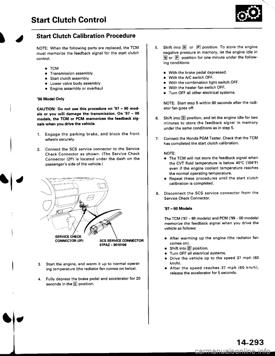
1. Engage the parking brake, and block the front
wheels securely.
2. Connect the SCS service connector to the Service
Check Connector as shown. (The Service Check
connector (2P) is located under the dash on the
passenger's side of the vehicle.)
CONNECTOR07PAZ - lDl01(xt
Start the engine, and warm it up to normal operat-
ing temperature (the radiator fan comes on twice).
Fully depress the brake pedal and accelerator for 20
seconds in the E] position.
rl ,
CONNECTOR I2PI
14-293
7.
Shift into E o|. E position. To store the engine
negative pressure in memory. Iet the engine idle in
E or E position for one minute under the follow-
ing conditions:
. With the brake pedal depressed,
. with the y'\/c switch oFF.
. With the combination light switch OFF.
. With the heater fan switch OFF.
. Turn OFF all other electrical systems
NOTE: Start step 5 within 60 seconds after the radi-
ator fan goes off.
Shift into E position, and let the engine idle for two
minutes to store the feedback signal in memory
under the same conditions as in step 5.
Connect the Honda PGM Tester. Check that the TCM
has completed the start clutch calibration.
NOTE:
. The TCM will not store the feedback signal when
the CVT fluid temperature is below 40"C (104'F)
even if the engine coolant temperature reaches
the normal operating temperature.
. Repeat these procedures until the start clutch
calibration is completed-
Disconnect the SCS service connector from the
Service Check Connector.
'97 - 00 Models
The TCM ('97 - 98 models) and PCM ('99 - 00 models)
memorize the feedback signal when you drive the
vehicle as follows:
. After warming up the engine (the radiator fan
comes onl.
. Shift into E position.
. Turn OFF all electrical systems,
. Drive the vehicle up to the speed 37 mph (60
km/h).
. After the speed reaches 37 mph (60 km/h),
release the accelerator for 5 seconds.
Page 1090 of 2189

lnspection and Adjustment
Pump Pressure Check
Check the fluid pressure as follows to determine
whether the trouble is in the pump or gearbox.
NOTE: First check the power steering fluid level andpump belt tension.
CAUTION: Disconnect the high pr$sure hos€ with care
so as not lo spill the power sieering tluid on tha frame
and other parts.
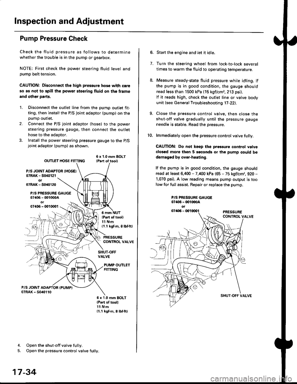
1. Disconnect the outlet line from the Dumo outlet fit-
ting, then installthe P/S joint adaptor (pump) on the
Dumo outlet.
2. Connect the P/S joint adaptor (hose) to the power
steering pressure gauge, then connect the outlet
hose to the adaptor.
3. Install the power steering pressure gauge to the P/Sjoint adaptor (pump) as shown.
ourlEr HosE FnrNo ,t"ll lrilu"ott
P/S JOINT ADAPTOB IHOSEI07RAK - S0i10l2rol07RAK- 50{{)120
P/S PRESSURE GAUGE07406 - 001000Aor07406 - 0010001
4. Open the shut-off valve fully.
5. Open the pressure control valve fully.
17-34
(Pa.t of tooll11 N.m11.1 kgt m, 8 lbf.ftl
PRESSURECONTROL VALVE
SHUT.OFFVALVE
PUMP OUTLETFITTING
6 x 1.0 mm BOLTlPart of tool)11 N.m11.1 kgf m, 8 lbtftl
7.
Start the engine and let it idle.
Turn the steering wheel from lock-to-lock several
times to warm the fluid to operating temperature.
Measure steady-state fluid pressure while idling. If
the pump is in good condition, the gauge should
read less than 1500 kPa (15 kgf/cmr, 213 psi).
lf it reads high, check the outlet line or valve body
unit (see General Troubleshooting 17-22).
Close the pressure control valve, then close the
shut-off valve gradually until the pressure gauge
needle is stable. Read the oressure.
lmmediately open the pressure control valve fully.
GAUTION: Do not keep lhe prossure control valve
clos€d more then 5 soconds or the pump could be
damagod by over-heating.
lf the pump is in good condition, the gauge should
read at least 6,400 - 7,400 kPa (65 - 75 kgflcm,, 920 -
1,070 psi). A low reading means pump output is too
low for full assist. Repair or replace the pump,
9.
P/S PBESSURE GAUGE07{16 -@1@OA
oi
SI{UT.OFF VALVE