1998 HONDA CIVIC cooling
[x] Cancel search: coolingPage 864 of 2189

Transmission
Installation {cont'd)
Connect the lock-up control solenoid connector. andinstall the transmission ground cable.
6 x '1.0 mm12 N.m {1.2 kgf.m, 8.7 lbl.ft}
LOCK.UP CONTROLSOLENOID CONNECTOR
Connect the staner cables on the staner motor. andinstall the cable holder.
NOTE; When installing the starter cable terminal.make sure that the crimped side of the ring terminalis facing out (see section 23).
6x1.0mm12 N.m 11.2 kg{.m.8.7 tbtftl
{0.9 kg'f.m, 7 lbf.ftl
TRANSMISSIONGROUND CABLE
b
14-186
STARTER CAELE
24. Installthe intake air duct.
D16Y7 engine:
Install the intake air duct and the resonaror.
D16Y8 engine:
lnstall the intake air duct and the air cleaner hous_ang assembly.
25. Refill the transmission with ATF (see page 14_1.18).
26. Connect the positive (+) cable first. then the nega-tive (-) cable to the battery.
27. Check the ignition timing (see section 23).
28. Start the engine. Set the parking brake, and shift thetransmission through all gears. three times. Checkthe shift cable adjustment (see page 14_190).
29, Check the front wheel alignment (see section 1g).
30. Let the engine reach operating temperature (thecooling fan comes on) with the transmission in Nor @ position, then turn it off and check the fluidlevel (see page 14- 7).
31. Road test as described on pages 14-113 thru ,14_116.
Page 881 of 2189
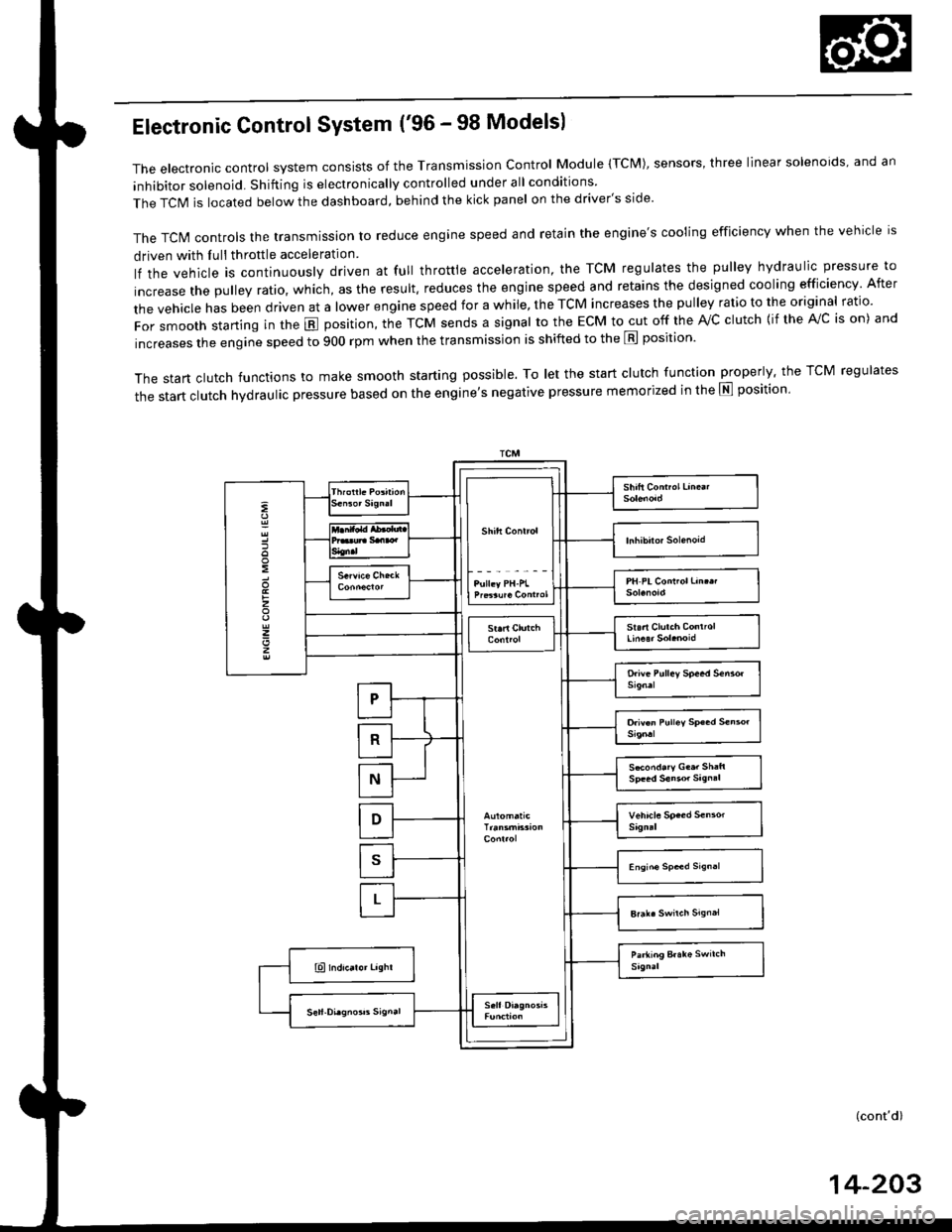
Electronic Control System ('96 - 98 Modelsl
The electronic control system consists of the Transmission control Module (TcM), sensors, three linear solenoids, and an
inhibitor solenoid. Shifting is electronically controlled under all conditions
The TCIM is located below the dashboard, behind the kick panel on the driver's side'
The TcN4 controls the transmission to reduce engine speed and retain the engine's cooling efficiency when the vehicle is
driven with Iull throttle acceleration
lf the vehicle is continuously driven at full throttle acceleration, the TCM regulates the pulley hydraulic pressure to
increase the pulley ratio, which, as the result. reduces the engine speed and retains the designed cooling efficiency After
the vehicle has been driven at a lower engine speed for a while, the TCM increases the pulley ratio to the original ratio.
For smooth starting in the E position, the TcM sends a signal to the EcM to cut off the rvc clutch {if the A!/c is on) and
increases the engine speed to 900 rpm when the transmission is shifted to the E position'
The start clutch functions to make smooth starting possible. To let the start clutch function properly. the TCM regulates
the start clutch hydraulic pressure based on the entine's negative pressure memorized in the E position'
:
:
z
z
z
S*ond.ry G..r Sh:ft
(cont'd)
14-203
Page 883 of 2189

Electronic Gontrol System ('99 - 00 Modelsl
The electronic controt system conststs of a Powertrain control Module (PCM). sensors, three linear solenoids and an
inhibitor solenoid. shifting is electronically controlled under all conditions A Grade Logic control system to control shift-
ing in E position while the vehicle is ascending or descending a slope'
fn"pCVirlocatedbelowthedashboard,underthekickpanelonthepassenger'sside'
The pCM controls the transmassion to reduce engine speed and retain the engine's cooling efficiency when the vehicle is
driven with full throftle acceleration
lf the vehicle is continuously driven at lull throttle acceleration, the PCM regulates the pulley hydraulic pressure to
increase the pulley ratio which. as the result, reduces the engine speed and retains the designed cooling efficiency After
the vehicle has been driven at a lower engine speed for a while, the PCM increases the pulley ratio to the original ratio'
i"i ".nl",rr starting in the E position, the PcM cuts off the ,Vc clutch (if the A/c is on) and increases the engine speed to
900 rpm when the transmission is shifted to the E position'
The start clutch functions to make smooth starting possible. To let the start clutch function properly, the PcM regulates
the start clutch hydraulic pressure based on the engine's negative pressure memorized in the E position'
FCM
s*o.d.ry G..t Sh.h
(cont'd)
14-205
Page 975 of 2189
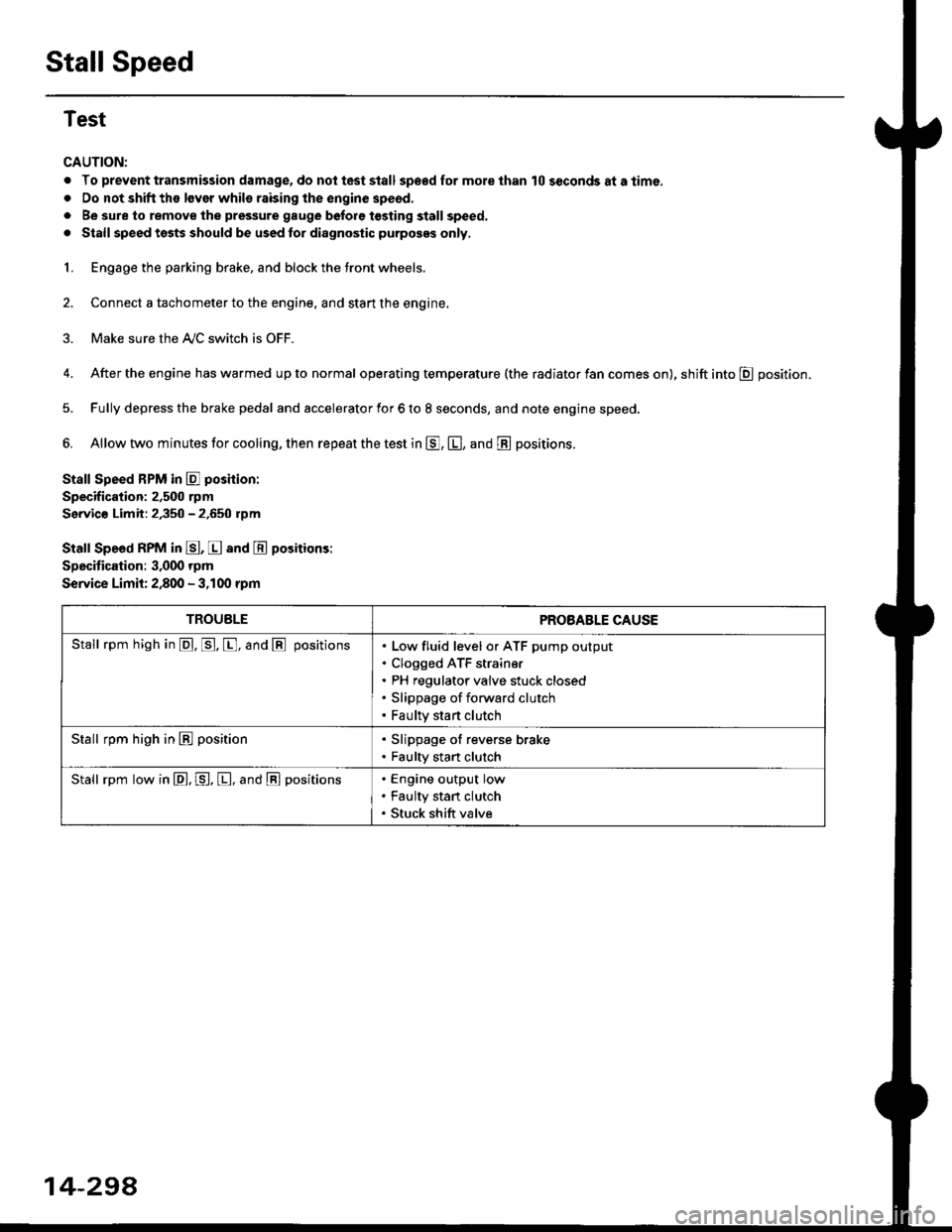
Stall Speed
Test
CAUTION:
. To prevent transmission damage, do not test stall sp€€d for mole than 10 seconds at a time.
. Do not shift the lsver whils raising the engine speod.
. Be sure lo remove the pressure gauge before tosting stall speed.
. Stall speed tssts should be used tor diagnostic purposes only,
1. Engage the parking brake, and block the tront wheels.
2. Connect a tachometer to the engine, and stan the engine.
3. Make sure the A/C switch is OFF.
4. After the engine has warmed up to normal operating temperature (the radiator fan comes on), shift into E position.
5. Fully depress the brake pedal and accelerator for 6 to 8 seconds, and note engine speed,
6. Allow two minutes for cooling, then repeat the test in E, E, and E positions.
Stall Speed BPM in E poshion:
Specification: 2,500 rpm
Servic€ Limit: 2,350 - 2.650 rpm
Stall Speed RPM in E, E and E positions:
Specitication: 3,000 rpm
Service Limit: 2,800 - 3,100 rpm
TROUBLEPROBABLE CAUSE
Stall rpm high in @. p. [, and @ positionsLow fluid level or ATF pump output
Clogged ATF strain€r
PH regulator valve stuck closed
Slippage of forward clutch
Faulty start clutch
Stall rpm high in E position. Slippage of reverse brake. Faulty start clutch
Stall rpm low in E, P, [, and @ positionsEngine output low
Faulty stan clutch
Stuck shift valve
14-294
Page 1380 of 2189
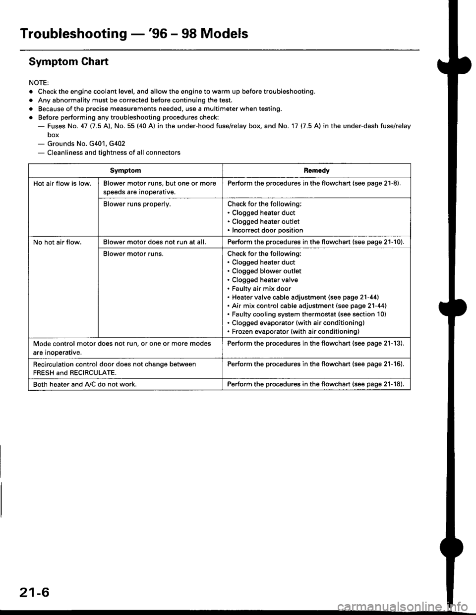
Troubleshooting -'96 - 98 Models
Symptom Chart
NOTE;
. Check the engine coolant level. and allow the engine to warm up before troubleshooting.
. Any abnormality must be corrected before continuing the test.
. Because of the precise measurements needed. use a multimeter when testing.
o Before performing any troubleshooting procedures check:- Fuses No. 41 11.5 Al, No. 55 (40 A) in the under-hood fuse/relay box. and No. 17 (7.5 A) in the under-dash fuse/relay
box- Grounds No. G401, G402- Cleanliness and tightness of all connectors
SymptomRomedy
Hot air flow is low.Blower motor runs. but one or more
speeds are inoperative.
Perform the procedures in the flowchart (see page 21-8).
Blower runs properly.Check for the following:. Clogged heater duct. Clogged heater outlet. Incorrect door position
No hot air flow.Blower motor does not run at all,Perform the procedures in the flowchart (see page 21-10).
Blower motor runs.Check for the following:. Clogged heater duct. Clogged blower outlet. Clogged heater valve. Faultv air mix door. Heater valve cable adjustment (see page 21-44). Air mix control cable adiustment (see page 2'l-441. Faulty cooling system thermostat (see section 10). Clogged evaporator (with air conditioning). Frozen evaporator {with air conditioning)
Mode control motor does not run, or one or more modes
are inooerative.
Perform the procedures in the flowchart (see page 21-13).
Recirculation control door does not chanqe between
FRESH and RECIRCULATE.
Perform the procedu.es in the flowchan (see page 21-16).
Both heater and A,/C do not work.Perform the procedures in the flowchart (see page 21-18),
21-6
Page 1414 of 2189
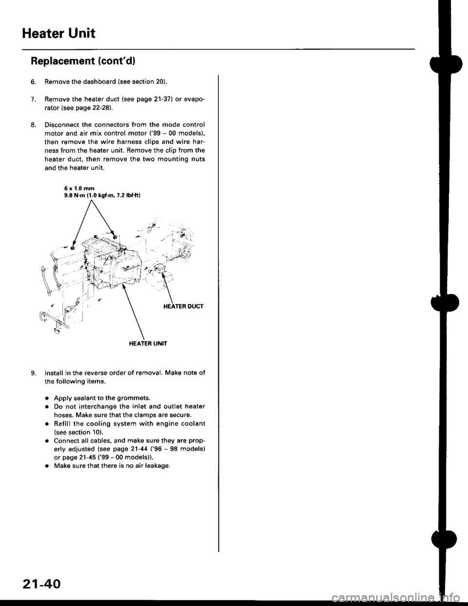
Heater Unit
Replacement (cont'dl
6.
7.
8.
9.
Remove the dashboard (see section 20).
Remove the heater duct (see page 21-37) or evapo-
rator (see page 22-28).
Disconnect the connectors from the mode control
motor and air mix control motor ('99 - 00 models),
then remove the wire harness clips and wire har-
ness from the heater unit. Remove the clip from the
heater duct, then remove the two mounting nuts
and the heater unit.
6x1.0mm9.8 N.m 11.0 kgl.m,7.2 lbf.ftl
HEATER UNIT
lnstall in the reverse order of removal. Make note of
the following items.
Apply sealant to the grommets.
Do not interchange the inlet and outlet heater
hoses. Make sure that the clamps are secure.
Refill the cooling system with engine coolant
(see section 10).
Connect all cables, and make sure they are prop-
erly adjusted (see page 21-44 (96 - 98 models)
or page 21-45 ('99 - 00 models)).
Make sure that there is no air leakage.
21-40
Page 1581 of 2189
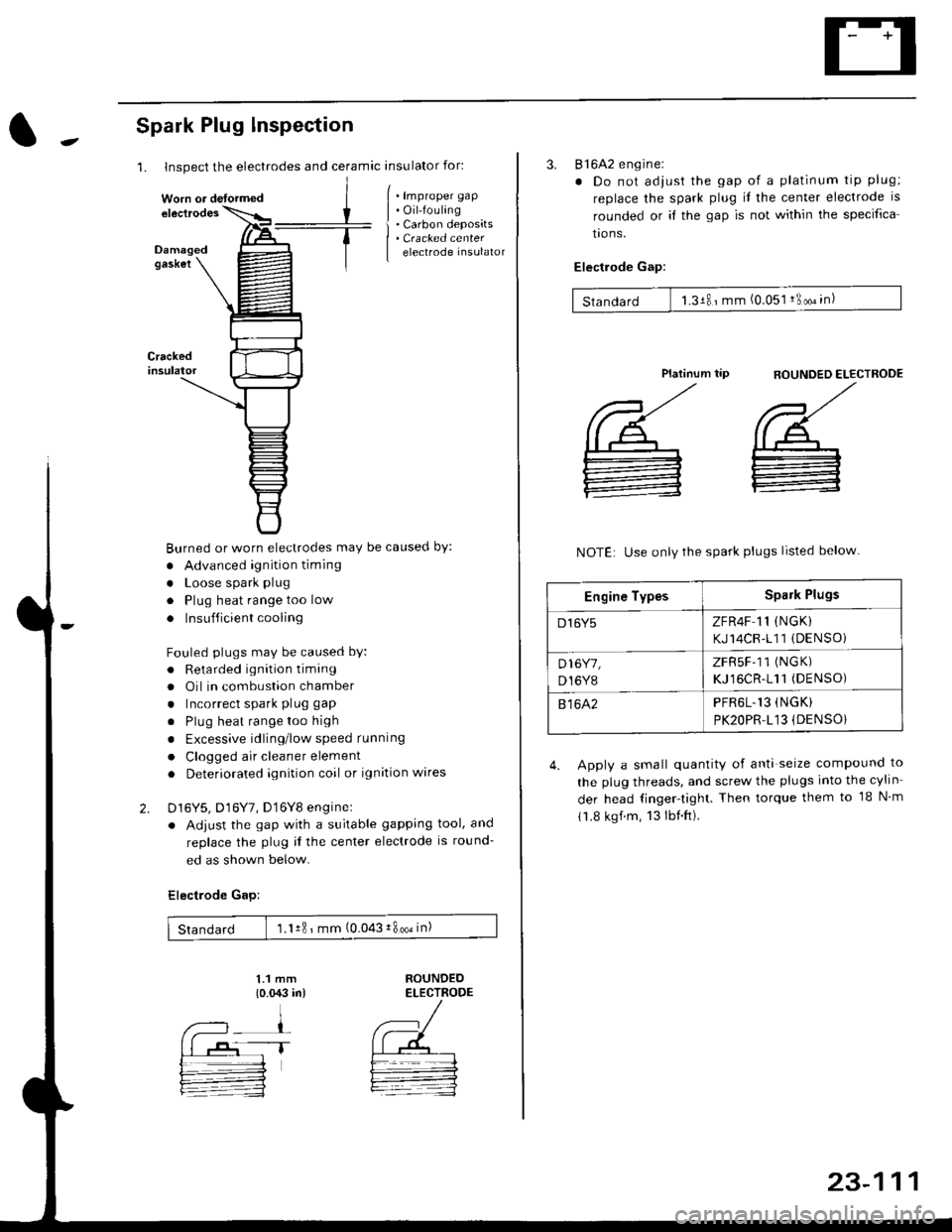
1. Inspect the electrodes and ceramic insulator for:
Spark Plug lnspection
Crackedinsulator
2.
[ . t.p,op", grp
| . Oil-fouling
i . Carbon deposits
| . Cracked center
I electrode insulator
Burned or worn electrodes may be causecl by:
. Advanced ignition timing
. Loose spark plug
. Plug heat range too low
. Insufficient cooling
Fouled plugs may be caused bY:
. Retarded ignition timang
. Oil in combustion chamber
. Incorrect spark plug gap
. Plug heat rangetoo high
. Excessive idling/low speed running
. Clogged air cleaner element
. Deteriorated ignition coil or ignition wares
D16Y5, D16Y7, D'16Y8 enginel
. Adjust the gap with a suitable gapping tool, and
replace the plug il the center electrode is round-
ed as shown below.
Electrode Gap:
1.1 mm
{o.{X:l in)ROUNDEDELECTRODE
Standard 1.1r8 ' mm (0.043i800oin)
Worn or detormed
1T
23-111
3. 816A2 engine:
. Do not adjust the gap of a platinum tip plug;
replace the spark plug il the center electrode is
rounded or it the gap is not within the specifica
tro ns.
Electlode Gap:
Standard 1.3181mm (0.051 !3oo" in)
flOUNDED ELECTROOE
',/
@_
:
Platinum tip
NOTE: Use only the spark plugs listed below
4. Apply a small quantity of anti seize compound to
the plug threads, and screw the plugs into the cylin
der head finger-tight. Then torque them to 18 N m
11.8 kgf.m, 13lbnft).
Engine TypesSpark Plugs
D16Y5ZFR4F 11 (NGK)
KJ14CR-111 (DENSOi
D16Y7,
D,I6Y8
ZFRSF-11 (NGK)
KJ16CR-111(DENSO)
81642PFR6L.13 (NGK)
PK2OPR.L13 (DENSO}
Page 1820 of 2189
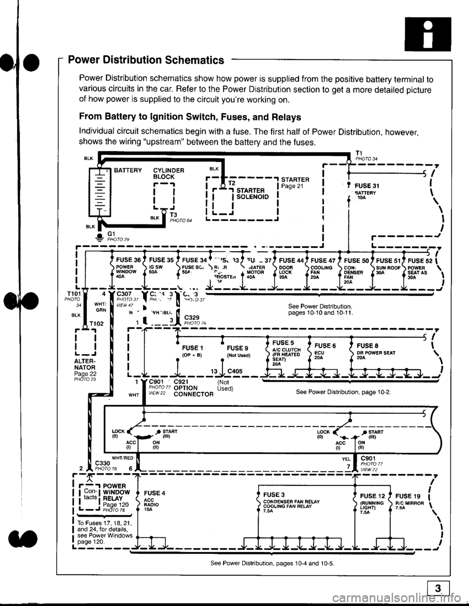
Power Distribution Schematics
Power Distribution schematics show how power is supplied from the positive battery terminal to
various circuits in the car. Refer to the Power Distribution section to get a more detailed picture
of how power is supplied to the circuit you're working on.
From Battery to lgnition Switch, Fuses, and Relays
Individual circuit schematics begin with a fuse. The first half of Power Distribution, however,
shows the wiring "upstream" between the battery and the fuses.
CYLINDERBLOCK
tl
tlL.lt J
",-* f ]fo,o
i BATTERY
IIII
-
----------------Y-?-
ruse so I ruse as I ruse ga | ' ,s. ,a I =u. - srl ruse aai ruse qr I ruse so I ruse sr i ruse iapowEF csw FUsE Bc, \F,.n .;,cren ooon \coounc cor,r. \sun noor powrnw'NDowf50a {* .i1-;.*"1liT""fi3f* f5# fffi'*"f'* fS?'*
- - -L - - -. ... Ji - -.J.- - - -e- - -l. - - -La - J- - - I - - -
"";%,, Y rtr,' .9 l' -%,t",,vtEw47 I ! See Power Dastribution,w - vH-,alr. lt - pages 10,10and 10-11.
' I ---il 9,1?-l--4F--?-
i I
t.urr, 'rrr.,
t i!?'.,,?"" t::=. l ty::.1----.-
-
i
a I r(op-B) .{Noru3€d) J$ifl#ii Jtocl }3fo**."".o'
t -L - - -L - - -: rJ:e'- - -Ei s+s-r -.Fl-J-Jrr.-.
It-STARTER | !Pase 21 ! t FUSE 31I "rn*i
I f
*
i.Jr;-t
i L_i***'" iL-------J
ilr------!
FUSE /I4 ' FUSE 47 ' FUSE 5{' ' FUSE 51' FUSE 52
rlr
OOOB \COOLING CON. \SUN BOOF FOWER
t3f* f5# fffi*" f'* fs?'*
See Power Dastribution,pages 10'10 and 10-11.
T101
34
ALK
4
GAN
I
I
I
I
I\
\I
I
I
FUSE 8DF POWEF SEAT204
FUSE 6ECU204
FUSE 5A/C CLUICH(FN HEATEDSEAD204
C901 C921 {NotPHoro zz OPTION Used)v/EW22 CONNECTOBSee Power Distnbution, page 10-2.
1
FUSE 4
FADIO104
c901
vlEw22
FUSE 12(BUltNrrGLIGHT)
FUSE 19R/C MIRROF
YEL
7
i-f,r-- 't PowERI uon- I Wlt{DOWi racrs i RELAY. t P^da 1tL-J P;dr1ii-
FUSE 3CONOENSEF FAN RELAYCOOLING FAN RELAY
To Fuses 17, 18, 21,and 24, for details,see Power Windowspage 120.a
ll
ll
ALTER-NATORPage 22
f102
c330
See Power Distribution, pages 10-4 and 10-5.