1998 HONDA CIVIC service
[x] Cancel search: servicePage 1756 of 2189
Troubleshooting
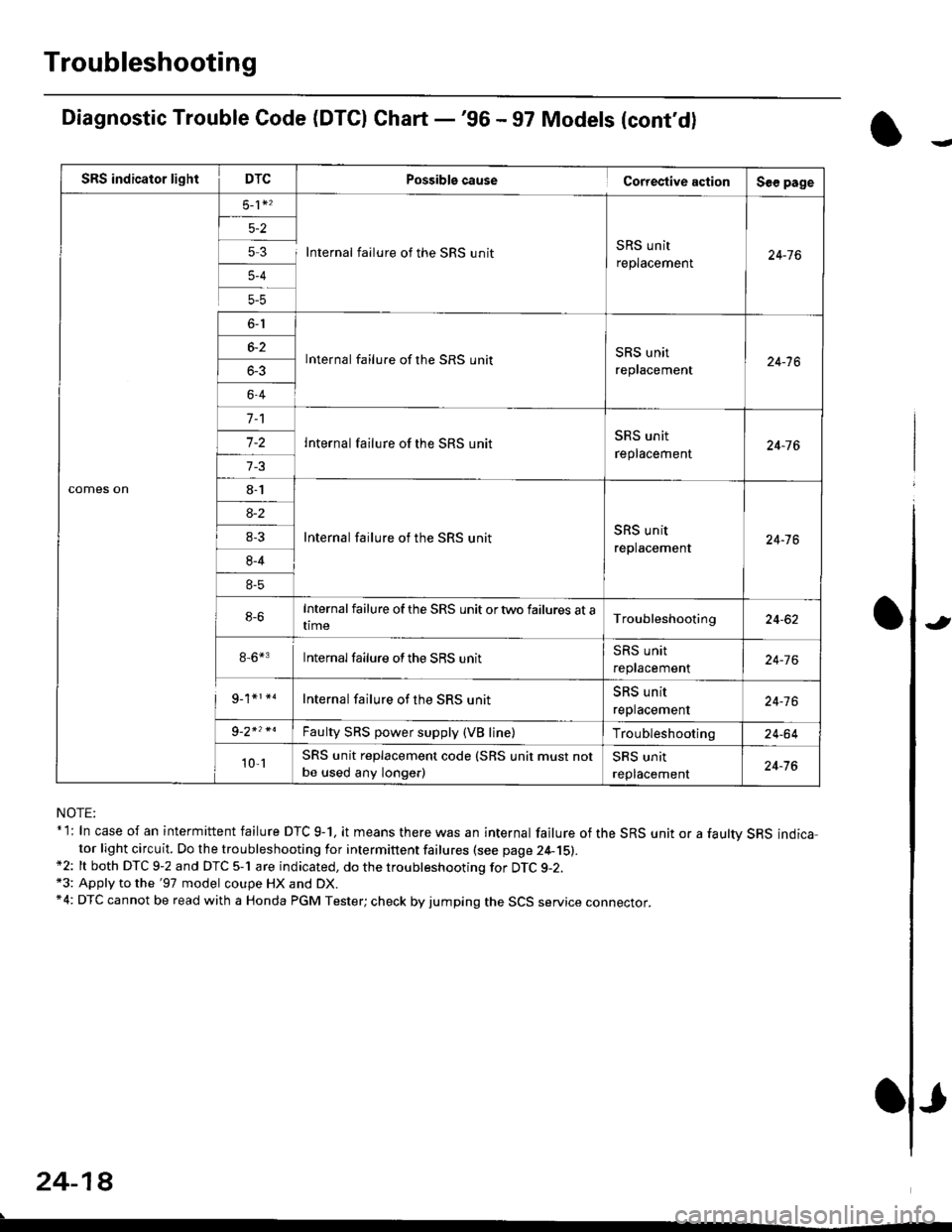
Diagnostic Trouble Code (DTCI Ghart -'96 - 97 Models (cont'd)
NOTE:* l: In case of an intermittent failure DTC g-1, it means there was an internal failure of the SRS unit or a faultv SRS indicator light circuit. Do the troubleshooting for intermittent failures (see page 24-15).*2: lt both DTC 9-2 and DTC 5-1 are indicated, do the troubleshooting for DTC g-2.*3: Apply to the '97 model coupe HX and DX.*4: DTC cannot be read with a Honda PGM Tester; check by jumping the SCS service connector.
24-18
.
Possiblg cause Cortestive action
5 3 I Internal failure of the SRS unitSRS unit
replacement
lnternal failure of the SRS unitSRS unit
replacement
Internal failure of the SRS unit
Internal failure of the SRS unitSRS unit
replacement
Internalfailure of the SRS unit ortwo failures at atime
8-6*3 Internalfailure ofthe SRS unit
Internal failure of the SRS unit
Faulty SRS power supply (VB line)
SRS unit replacement code (SRS unit must not
be used any longe.)
J
Page 1758 of 2189
Troubleshooting
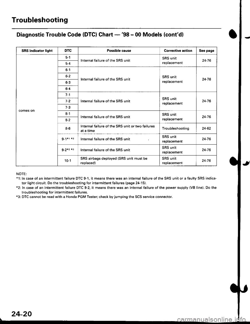
Diagnostic Trouble Code (DTC) Chart -'98 - 00 Models {cont'dl
NOTE:* 1: In case of an intermittent failure DTC 9-1, it means there was an internal failure of the SRS unit or a faulty SRS indica-
tor light circuit. Do the troubleshooting for intermittent failures (page 24-'15).*2: In case of an intermittent failure DTC 9-2, it means there was an internal failure of the power supply {VB line). Do the
troubleshooting for intermiftent failures.*3: DTC cannot be read with a Honda PGM Tester; check by jumping the SCS service connector.
24-20
\
SRS indicator lightDTCPossible causeCorrectiYe actionSee page
comes on
5-1lnternal failure of the SRS unitSRS unit
replacemenl24-765-4
6-1
lnternal failure of the SRS unitSRS unit
replacement24-7 66-2
o-5
6-4
7-1
lnternal failure of the SRS unitSRS unit
replacement24-76
7-3
8-1lnternal failure of the SRS unitSRS unit
reptacement24-7 68-2
8-6Internal failure of the SRS unit or two failures
at a trmeTroubleshooting24-62
g_1*r *3lnternal failure of the SRS unitSRS unit
replacement24-7 6
9-2+2 *3lnternal failure of the SRS unit5l|5 Untr
replacement24-76
10-1SRS airbags deployed (SRS unit must be
reDlaced)
SRS unit
replacement24-76
Page 1760 of 2189
Troubleshooting
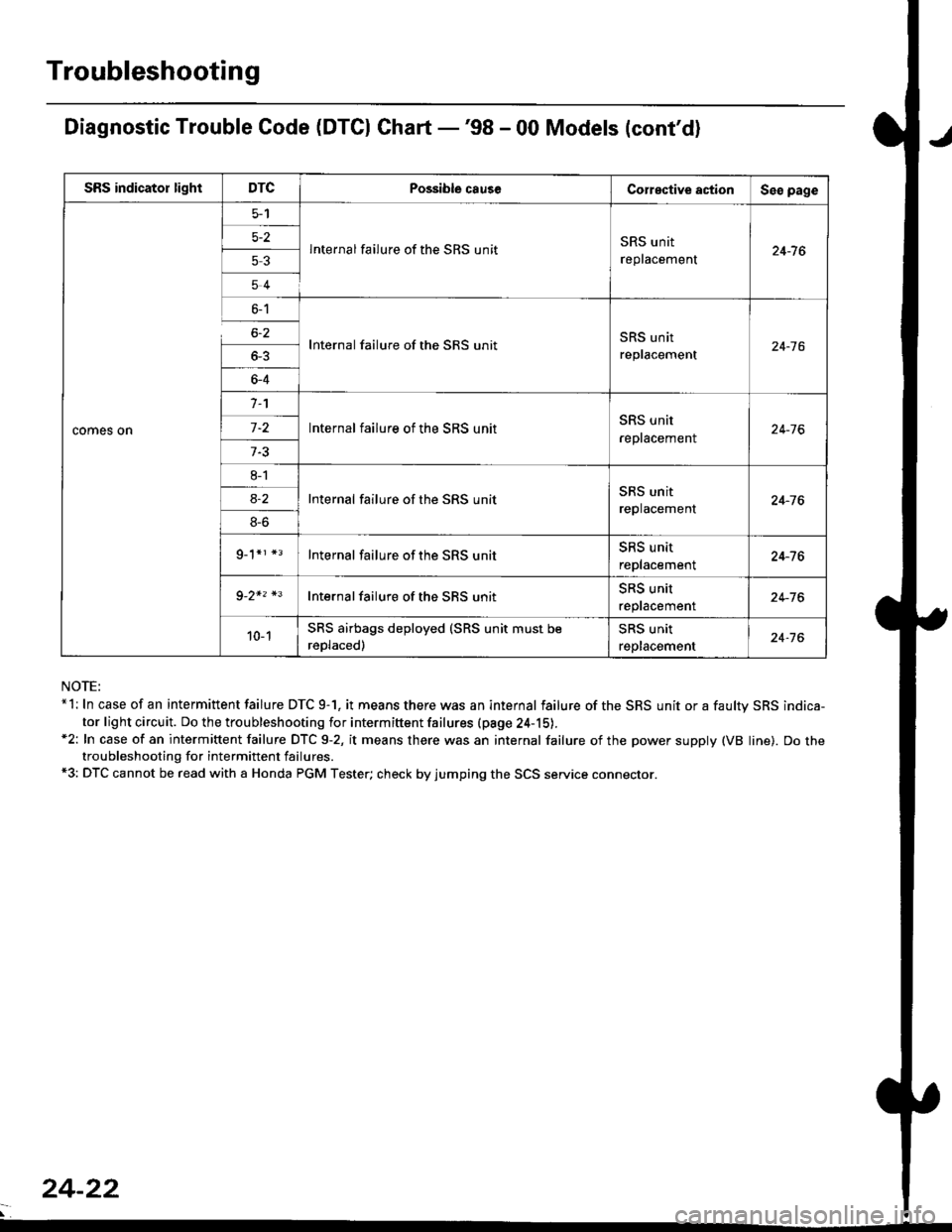
Diagnostic Trouble Code (DTCI Ghart -'98 - 00 Models (cont'd)
NOTE:*l: In case of an intermittent failure DTC 9-1. it means there was an internal failure of the SRS unit or a faultv SRS indica-
tor light circuit. Do the troubleshooting for intermiftent failures (pa9e 24-15).*2: In case of an intermittent failure DTC 9-2, it means there was an internal failure of the power supply (VB line). Do thetroubleshooting for intermittent failures.*3: DTC cannot be read with a Honda PGM Tester; check by jumping the SCS service connector.
SRS indicator lightDTCPossible causeCorective actionSeo page
comes on
5-2
53
54
lnternal failure of the SRS unitSRS unit
replacement24-7 6
6-1
6-2
_
64
Internal failure of the SRS unitSRS unit
replacement24-16
n
-
8l
8S
9_1*r *3
Internal failure of the SRS unitSRS unit
reptacement24-76
Internal failure of the SRS unitSRS unit
replacement24-76
Internal failure of the SRS unitSRS unit
replacement24-76
Internal failure of the SBS unitSRS unit
reptacemenr24-76
10-1SRS airbags deployed (SRS unit must be
reDlaced)
SRS unit
replacement24-76
24-22
Page 1762 of 2189
Troubleshooting
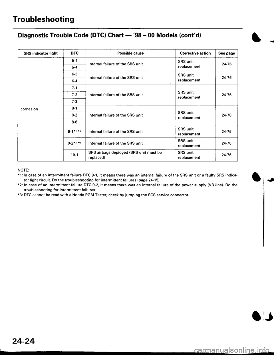
Diagnostic Trouble Code (DTG) Chart -'98 - 00 Models (cont'dl
NOTE:*'l: In case of an intermittent failure DTC 9-1. it means there was an internal failure of the SRS unit or a faulty SRS indica-
tor light circuit. Do the troubleshooting for intermiftent failu.es (page 24-15).*2: In case ot an intermittent failure DTC 9-2. it means there was an internal failure of the power supply (VB line). Do the
troubleshooting for intermift ent failures.*3: DTC cannot be read with a Honda PGM Tester; check by jumping the SCS service connector.
24-24
a,
SRS indicator lightDTCPossible causeCorective actionSee page
comes on
lnternal failure of the SRS unitSRS unit
repracemenl24-765-4
6-3lnternal failure of the SRS unitSRS unit
reptacemenr24-766-4
Internal failure of the SRS unitSRS unit
replacement24-7 6
8-1
lnternal failure ot the SRS unitSRS unit
replacement24-7 68-2
8-6
g_1*r *rInternal failure of the SRS unitSRS unit
replacement24-16
lnternal failure of the SRS unitSRS unit
repracemenl24-76
10-1SRS airbags deployed (SRS unit must be
.eplaced)
SRS unit
reptacemenl24-76
Page 1767 of 2189
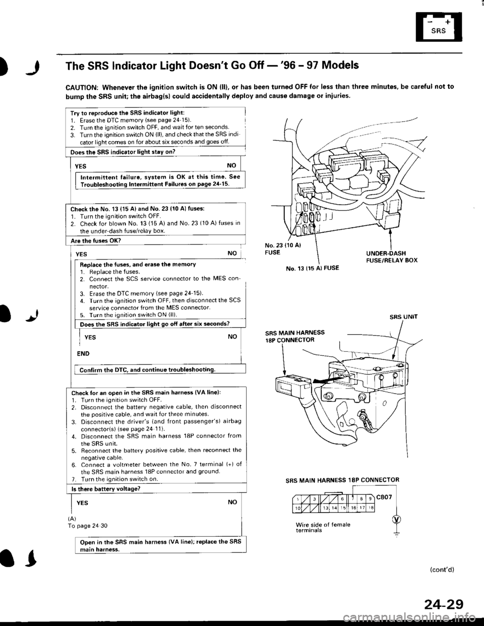
)The SRS lndicator Light Doesn't Go Off -'96 - 97 Models
CAUTION: Whenever the ignition switch is ON (ll), or has been turned OFF for less than three minutes, be careful not to
bump the SRS unit; the airbag{sl could accidentally deploy and cause damage or iniuries
Try to reproduce lhe SRS indicator light:
1. Erase the DTC memory (see page 24'15).
2. Turn the ignition switch OFF, and wait for ten seconds.
3- Turn the ignition switch ON {ll), and check that the SRS indi
cator light comes on for about six seconds and goes off
Does the SRS indicEtor light stay on?
[*NO
Intermittent lailure, system is OK at this time. See
Troubloshooting Int6rmittent Failures on page 24'15
Ch€ck the No. 13 {15 A} and No. 23 (10 A) fuses:
1. Turn the ignition switch OFF.
2. Check for blown No. 13 (15 A) and No.23 (10 A)fuses in
the under dash fuse/relay box.
Are the fuses OK?
vEs No
Replace the luses, and erase the memory1. Replace the fuses.2. Connect the SCS service connector to the MES con
nector.3. Erase the DTC memory (see page 24 15).
4. Turn the ignitaon switch OFF, then disconnect the SCS
service connector from the MES connector.5. Turn the ignition switch ON (ll).
Does the sRS indicato, tigt t go or "ne. "ii--JJl
-I YEs NO1
ENDi
Conlirm the DTC, and continue troubl6shootilg.
Check for an open in the SRS main harness {VA linell'1. Tu.n the ignition switch OFF.
2. Disconnect the battery negative cable, then disconnect
the positive cable, and wait for three minutes.
3. Disconnect the driver's (and front passenger's) airbag
connectorls) (see page 24 11).
4. Disconnect the SBS main harness '18P connector from
the sRS unir.5, Reconnect the battery positive cable, then reconnect the
negative cable.6. Connect a voltmeter between the No. 7 tetminal (+) of
the SRS main harness 18P connector and ground.
7. Turn the ignition switch on.
b there battery voltageT
YESNO
(A)
To page 24 30
Open in the SRS main harness IVA line); replace the SRS
main harness.
l.J
SBS MAIN
(cont'd)
No. 't3 {15 Al FUSE
SRS UNIT
HARNESS 18P CONNECTOR
II
24-29
Page 1784 of 2189
Troubleshooting
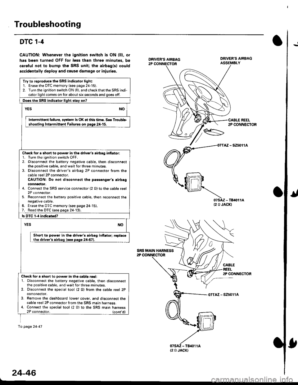
!DTC 1-4
CAUTION: Whenever ths ignition 3wiich is ON {lll, or
has boen turned OFF tor loss than three minutes, bs
caroful not to bump the SRS unit; the airbagls) could
accidoDtally deploy and cause damage or iniulies.
07SAZ - TB,()11A(2 0 JACKI
CABLEREEL2P CONNECTOR
07TAZ - Szsol'�lA
24-46
DRIVER'S AIRBAG
CABLE REEL2P CONNECTOR
Try to roproduc. the SRS indic.lor lightr1. Erase the DTC memory (see page 24-15).2. Turn the ignition switch ON (ll), and check that the SRS indi-cator light comes on tor about six seconds and goes off.
Ooes th6 SRS indicltor liqht stey on?
YESNO
Intermitid{ failure, 3y3tem b OK at this time. S€e Troublo-shooting Intormittont Failurss on pago 24.15.
Check for a 3hort to powo. in the d.iver's .irbag inflator:1. Turn the ignition switch OFF.2. Disconnect the baftery negative cable, then disconnectthe positive cable, and wait for three minut6s.3. Disconnect the driver's airbag 2P connector from thecable reel 2P connector.CAUTION: Do not disconnoct the parsengcr'r airbagconnactoa.4. Connect the SRS service connector (2 O) to the cable reel2P connector.5. Reconnect the battery positive cable, then reconnect thenegative cable.6. Erasethe DTC memory (see page 24-15).7. Read th6 DTC {seo page 24-13},
ls OTC 1-4 indic.tedT
YESNO
Short to pow.r in the driver'i rirbrg inilrtor; r€pl.cothe driver'! airbag l!e. paga 24-67).
Check for a ahort to Dow€r in tha crblo.eet:1. Disconnect the battery negative cabl€, then disconnectthe positive cable, and wait for three mrnur€s.2. Disconnect the special tool (2 O) trom the cable reel 2Pcononector.3. Bemove the dashboard lower cover, and disconnect thecable reel 2P connector trom th€ SRS main harness.4. Connect the special tool 12 0) to the SRS main harness2P connector. (cont'd)
fo page 24-47
SRS MAIN HABNESS
t2 0 JACK)
Page 1808 of 2189
Airbag
Disposal
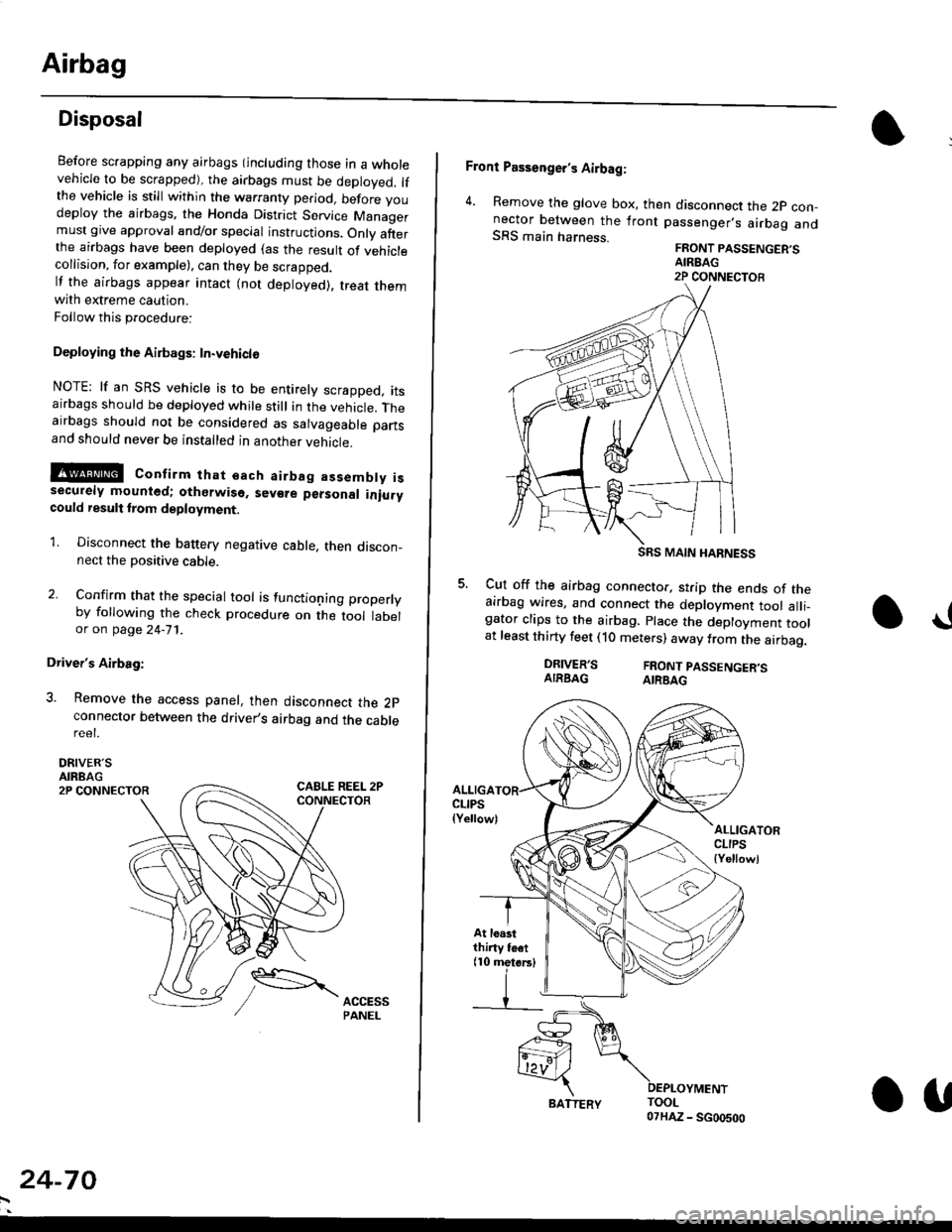
Before scrapping any airbags (including those in a wholevehicle to be scrapped), the airbags must be deployed. lfthe vehicle is still within the warranty period, before youdeploy the airbags, the Honda District Service Managermust give approval and/or special instructions. Onlv afterthe airbags have been deployed (as the result of vehiclecollision, for example), can they be scrapped.lf the airbags appear intact (not deployed). treat themwith extreme caution.
Follow this p.ocedure:
Deploying the Airbags: In.vehiclo
NOTE: lf an SRS vehicle is to be entirely scrapped, itsairbags should be deployed while still in the vehicle. Theairbags should not be considered as salvageable partsand should never be installed in another veh;cle.
!@ confirm thst oach airbag assembty issecurely mounted; otharwiso. sev€re personal iniurycould result lrom deployment.
1. Disconnect the baftery negative cable, then discon_nect the positive cable.
2. Confirm that the special tool is functioning properlyby following the check procedure on the tool labelor on page 24-'l'l .
Driver's Airbag:
3. Remove the access panel, then disconnect the 2pconnector between the driver,s airbag and the cablereet.
DRIVER'SAIRBAG2P CONNECTOR
24-70
BATTERY.U
Front Passenger's Airbag:
4. Remove the glove box, then disconnect the 2p con-nector between the lront passenger,s airbag andSRS main harness.FRONT PASSENGER'SAIREAG2P CONNECTOB
SRS MAIN HARNESS
Cut off the airbag connector, strip the ends of theairbag wires, and connect the deployment tool alli_gator clips to the airbag. place the deployment toolat least thirty feet (10 meters) away from the airbag.
a!
DRIVER'SAIRBAGFRONT PASSENGER'SAIRBAG
ALLIGACLIPS(Yellow)ALLIGATORCLIPS{Yellowl
At loastthiny toet(10 metorsl
Page 1809 of 2189
E-
)I
Connect a 12 volt battery to the tool:
. lf the green light on the tool comes on, the aar-
bag igniter circuit is defective and cannot deploy
the airbag. Go to Damaged Airbag Special
Procedure.
. lf the red light on the tool comes on, the airbag is
ready to be deployed.
Push the tool's deployment switch. The airbag
should deploY (deployment is both highly audible
and visible; a loud noise and rapid inflation of the
bag, followed by slow deflation).
. lf the airbags deploy and the green light on the
tool comes on. continue with this procedure.
. l{ an airbag doesn't deploy, yet the green light
comes ON, its igniter is defective. Go to Dam-
aged Airbag Special Procedure.
!!@ During doployment, the airbag sssom'
bly can become hot enough to buln you. Wait thir'
ty minutes aftsr deployment belore touching tho
assembly.
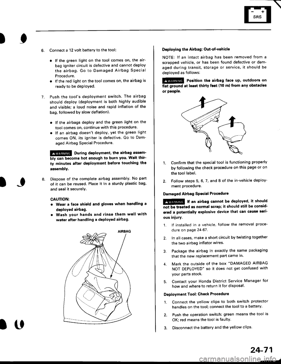
Dispose of the complete airbag assembly. No part
of it can be reused. Place it in a sturdy plastic bag,
and seal it securelY,
CAUTION:
. Wear a fsce shield and gloves when handling a
deployed airbag.
. Wash your hands and rinse them well with
wat6r after handling. deployed airbag.
t('
24-71
7.
AIRAAG
Doploying th6 Airbag: Out-of-vehicle
NOTE: lf an intact airbag has been removed from a
scrapped vehicle. or has been found defective or dam-
aged during transit, storage or service, it should be
deployed as follows:
@ Po3ition the airbag laca up, outdoors on
flat ground at lsast thirty f€€t (t0 ml from any obstacles
or people.
1. Confirm that the special tool is tunctioning properly
by following the check procedure on this page or on
the tool label.
2. Follow steps 5, 6, 7, and I of the in-vehicle deploy-
menl Drocequre.
Damaged Airbag Spacial Procedure
!@ r an airb.g cannot be deployed, it should
iiiTi-treatcd as normal scrap; il should still be consid-
srsd a potontially oxplosive device that can cau3o ssti-
ous iniury.
1. lf installed in a vehicle, lollow the removal proce-
dure on page 24-67.
2. In all cases. make a short circuit by twisting together
the two airbag inflator wires.
3. Package the airbag in exactly the same packaging
that the new replacement part came in.
4. Mark the outside of the box "DAMAGED AIRBAG
NOT DEPLOYED" so it does not get confused with
your Parts stock.
5. Contact your Honda District Service Manager for
how and where to return it for disposal.
Deployment Tool: Check Procedur€
1. Connect the yellow clips to both switch protector
handles on the tool; connect the tool to a battery.
2. Push the operation switch: green means the tool is
OK: red means the tool is faulty
3. Disconnect the battery and the yellow clips.