Page 481 of 2189

ldle Control System
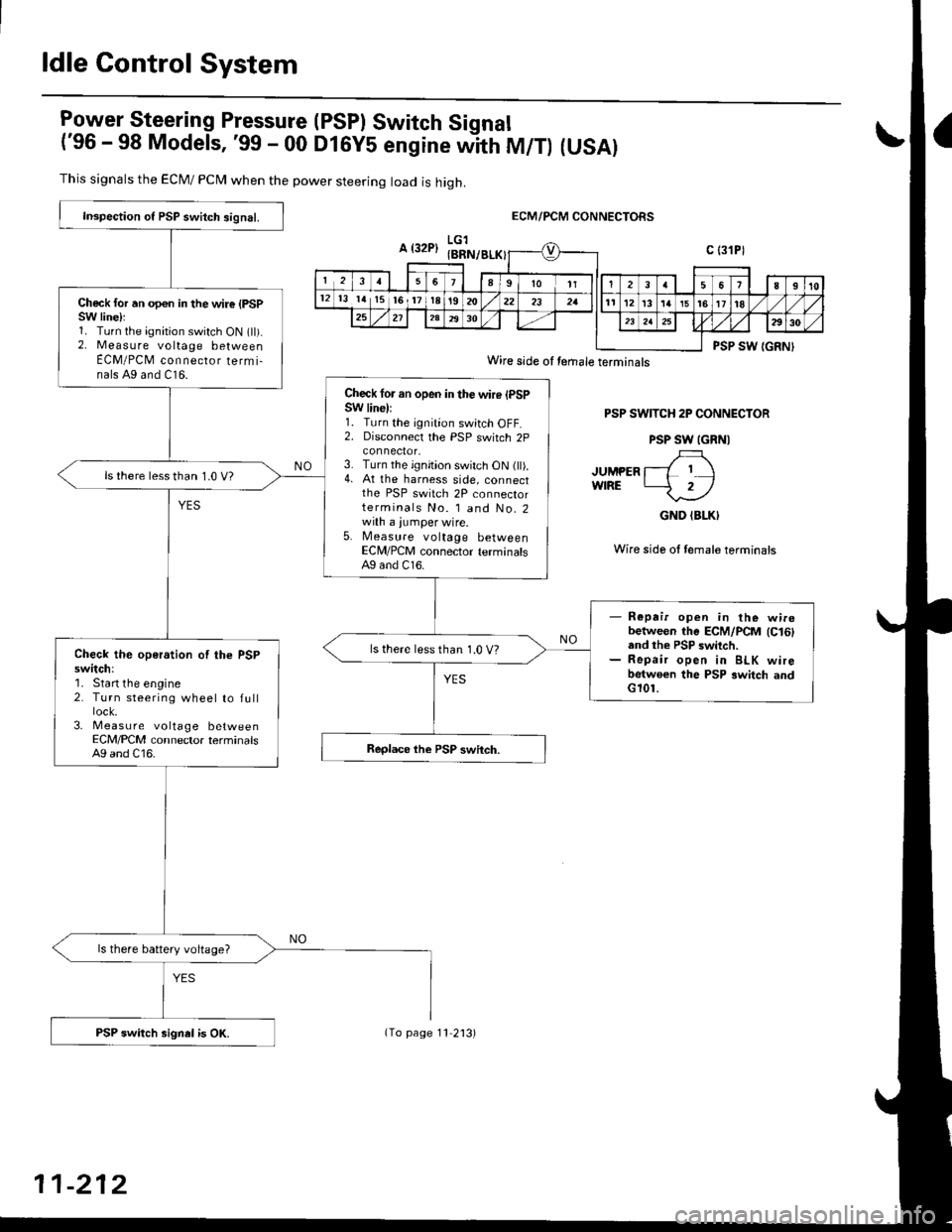
lgy"t9!"_"ring Pressure (PSPI Switch Signal
('96 - 98 Models, '99 - 00 DlGy5 engine witn fU/f) (USAI
This signals the ECM/ PCN4 when the power steering load is high.
ECM/PCM CONNECTORS
PSP SWITCH 2P CONNECTOR
PSP SW IGRNI
JUMPER l--L I IwfRE -2/
GND (BLKI
Wire side ol female terminais
Inspection o{ PSP switch signal.
Check for an opon in the wire {PSPSW linelr1. Turn the ignition switch ON (ll).2. Measure voltage betweenECM/PCM connecror termi-nals A9 and C16.
Check lor an open in the wire (PSPSW line):1. Turn the ignition switch OFF.2. Disconnecl the PSP switch 2p
3. Turn the ignition switch ON (ll).4. At the harness side, connectthe PSP switch 2P connectorterminals No. l and No.2with a jumper wire.5. Measure voltage betweenECM/PCM connector terminalsAg and C16.
ls there lessthan 1.0 V?
- Repair open in the wirobetween the ECM/PCM lc16land the PSP switch.- Repair open in BLK wirebetwoen the PSP switch andG101.
ls there less than 1.0 V?Check the operation of the PSPswitch:'1. Start the engine2. Turn steering wheel to full
3- Measu re voltage betweenECM/PCM connector terminalsA9 and C16.
ls there battery voltage?
PSP switch signel is OK.
Wire side oI temale terminals
11-212
(To page 11'2'13)
Page 483 of 2189

ldle Control System
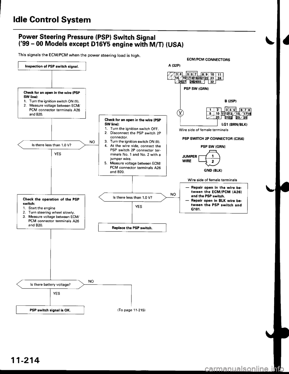
Power Steering Pressure (PSP) Switch Signal
('99 - 00 Models except Dl6y5 engine with M/T) (USAI
This signals the ECM/PCM when the power steering load is high.
Wire side of female terminals
PSP SWTTCH 2P CONNECTOR (qts6)
PSP SW (GRN)
JUMPER T---7 1 \wlRE LJ- 2-l
GND IBLK)
Wi16 sid6 of temale terminals
ECM/PCM CONNEgTORS
Inspoction ot PSP switch signal.
Check for an op€n in the wire (PSPSW linel:1. Turn the ignition switch ON (ll).2. Measure voltage between ECN4/PCM connector terminals 426and 820.
Check for .n open in tho wire IPSPSW line):1. Turn the ignition switch OFF.2. Disconnoct the PSP switch 2Pconnector.3. Turn the ignition switch ON (ll).4. At the wire side, connect thePSP switch 2P connector ter-minals No. 1 and No.2 with ajumper wire.5. Measure voltage between ECM/PCNI connoctor terminals 426and 820.
ls there lessthan 1.0 V?
- Ropai. opgn in ths wire be-tw.€n the ECM/PCM {A261rnd th6 PSP switch.- Ropsir opon in BLK wi.o bo-twoen tho PSP switch andG101.
ls there less than 1.0 V?Check the operation ot the PSPsw;tch:'1. Start the engine2. Turn steering wheelslowly.3. Measure voltage between ECM/PCM connector terminals 426and 820.
ls there battery voltage?
PSP switch sign8l i3 OX.
11-214
(To page 11-215)
Page 493 of 2189
Fuel Supply System
Fuel Lines
NoTE: Check fuel system lines, hoses, fuel filter, and other components lor damage, leaks and deterioration, and replaceif necessary.
(2.2 kgt.m, 16lbf.ft)(D16Y5 engine: 28 N.m2.8 kgtm, 21 lbf ft)
The illustrationshows'99 00 models.
t/
,ee.- ;
4/
/.,/
Tl...,.' ..4,/
i,/
I
22 N.m
11-224
Page 494 of 2189
I'96 - 98 models:
NOTE: Check all hose clamps and retighten if necessarY.
M
/vFUELFILTER
PRESSUREREGULATOR
IFUELTANKFUELGAUGESENDINGUNITBASE GASKETReplace.
Clamp In rhe middle
@
Clamp in the middle
10-14mm(0.39 - 0.55 inl
(cont'd)
11-225
Page 495 of 2189
Fuel Supply System
Fuel Lines (cont'dl
.99 - 00 models:
NOTE: Check all hose clamps and retighten if necessary.
: Do not disconnect the hose from the pipe.
ONBOARD REFUELING VAPORBECOVERY IORVRIVENT SHUT VALVE
B
FUELGAUGElt N.rn l1.a kgt.m,r0 lbt ftl
ftr, n'fo'PRESSUREREGULATOR
Clamp in the middle
Clamp in the middle
11-226
Page 499 of 2189

Fuel Supply System
System Description
The fuel supply system consists of a fuel tank, in-tank
high pressure fuel pump, PGM-FI main relay, fuelfilter,
fuel pressure regulator, fuel injectors. and fuel delivery
and return lines. This system delivers pressure-regu-
lated fuel to the fuel injectors and cuts the fuel delivery
when the engine is not running.
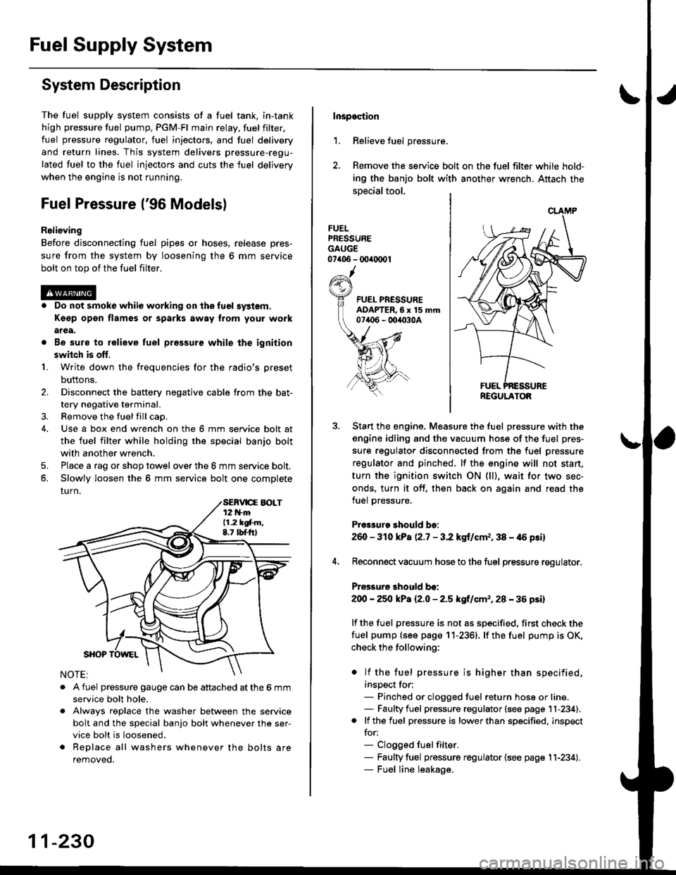
Fuel Pressure l'96 Modelsl
Relieving
Before disconnecting fuel pipes or hoses, release pres-
sure from the system by loosening the 6 mm service
bolt on top of the fuel filter.
. Do not smoke whil6 working on the fuel system.
Kgsp opon flames or sparks away from youl work
area.
. Be sure to relieve fuel pressure while the ignition
switch is off.
1. Write down the frequencies for the radio's preset
buttons.
2. Disconnect the battery negative cable from the bat-
tery negative terminal.
3. Remove the fuelfill cap,
4. Use a box end wrench on the 6 mm service bolt at
the fuel filter while holding the special banjo bolt
with another wrench,
5. Place a rag or shop towel over the 6 mm service bolt.
6, Slowly loosen the 6 mm service bolt one complete
rurn.
. A fuel pressure gauge can be attached at the 6 mm
service bolt hole.
. Always reDlace the washer between the service
bolt and the special banjo bolt whenever the ser-
vice bolt is loosened.
. Replace all washers whenever the bolts are
removeo.
11-230
Inspoction
1. Relieve fuel pressure.
2. Remove the service bolt on the fuel filter while hold-
ing the banjo bolt with another wrench. Attach the
special tool.
FUELPRESSUREGAUGE07406 - 00ir0(x)1
Start the engine. Measure the fuel pressure with the
engine idling and the vacuum hose of the fuel pres-
sure regulator disconnected from the fuel pressure
regulator and pinched. lf the engine will not start,
turn the ignition switch ON (ll), wait for two sec-
onds, turn it off, then back on again and read the
fuel pressure.
Pr€3sure should bo:
260 - 310 kPa (2.7 - 3.2 kgt/cmr, 38 - 46 psi)
Reconnect vacuum hose to the fuel pressure regulator,
Pressure should bo:
200 - 25O kPa l2.O - 2.5 kgf/cm'�, 28 - 36 psil
lf the fuel pressure is not as specified, first check the
fuel pump {see page 11-2361. lf the fuel pump is OK,
check the following:
. lf the fuel pressure is higher than specified,
inspect for;- Pinched or clogged fuel return hose or line.- Faulty fuel pressure regulator (see page 11-234).. lf the fuel pressure is lower than specified, inspect
for:- Clogged fuelfilter.- Faulty fuel pressure regulator {see page 11-234).- Fuel line leakage.
REGULATOB
Page 500 of 2189

tJFuel Pressure {'97 and later Models)
ReliGving
Before disconnecting tuel pipes or hoses, release pres-
sure from the system by loosening the 12 mm banjo
bolt on top of the fuel filter.
@o Do not smoke whilo working on the fuel sy3lom.
Ksgp op€n flames or sparks away tlom Your work
arga.
. Be sure to relieve fuel pressule while the ignition
swhch is off.
1. Write down the frequencies for the radio's preset
buttons,
2. Disconnect the battery negative cable from the bat-
tery negative terminal.
3. Remove the fuel fill cap.
Use a box end wrench on the 12 mm banjo bolt at
the fuel filter while holding the fuel filter with anoth-
er wrench.
Place a rag or shop towel over the 12 mm banio bolt.
Slowly loosen the 12 mm banjo bolt one complete
turn.
4.
I
12 mm BAtt OBOLT33 N.m (3.i1 kgf m,25 tbf.f0
NOTE: Replace all the washers whenever the 12
mm banio bolt is loosened or removed.
Inspaqtion
1. Relieve fuel pressure.
2. Remove the 12 mm banjo bolt from the fuel filter
while holding the fuel Jilter with another wrench
Attach the special tools.
3. Start the enginethe fuel Pressure with the
engine idling and the vacuum hose of the fuel pres-
sure regulator disconnected from the fuel pressure
regulator and pinched lfthe engine will not start, turn
the ignition switch ON {ll), wait for two seconds, turn
it off, then back on again and read the fuel pressure'
Pr$3uro ehould be:
excepi 816A2 sngine:
260 - 310 kPa {2'7 - 3.2 kgf/cm" 38 - {6 Fi}
B16A2 engine:
27O -32O kPa P.8 - 3'3 kgf/cm'�, '10 - 47 psi)
4. Reconnect vacuum hoso to the fuel pressure regulator'
Pre33ure 3hould be:
except B16A2 engin€:
2OO - 250 kPa {2.0 - 2'5 kgf/cm'�, 28 - 36 psi)
B16A2 engino:
210 - 260 kPa 121 - 2.6 ksf/cm'�, 30 - 37 psi)
lf the fuel pressure is not as specified, first check the
fuel pump (see page 11-236) lfthetuel pumpisoK,
check tho following:
. lf the fuel pressure is higher than specified,
inspect for:- Pinched or clogged fuel return hose or line.
- Faulty fuel pressure regulator (see page 11-
2341.
. lf the fuel pressure is lower than specified, inspect
for:- Clogged fuel filter.
- Faulty fuel pressure regulator (see page l1-
2341.- Fuel line leakage.
FUEL PRESSUREADAPTER BOLT, 12 mm
tguxt8-PD6-0101
CLAMP
REGULATOR
11-231
Page 504 of 2189

I
FuelFilter
Replacement
r@. Do not smoke whilc working on fuel system. Keep
open flame away from your work arsa.
. While replacing the tuel filter, be catelul to koep a
sale distance betwoen battery torminals and any
tools.
The fuel filter should be replaced whenever the fuel
pressure drops below the specified value [260 - 310 kPa
12.7 - 3.2 ksl/cm'�,38 - 46 psi), |270 - 320 kPa (2.8 - 3 3
kgf/cm,, 40 - 47 psi))* with the fuel pressure regulator
vacuum hose disconnected and pinchedl after making
sure that the fuel pump and the fuel pressure regulator
are OK. *: 81642 engine
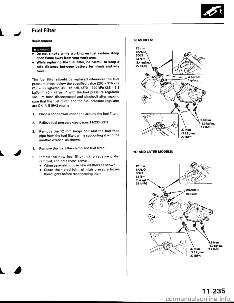
1. Place a shop towel under and around the fuelfilter.
2. Relieve fuel pressure (see pages 11-230,231]-
Remove the 12 mm banjo bolt and the fuel feed
pipe from the fuel filter, while supporting it with the
another wrench, as shown.
Remove the fuel filter ciamp and fuel filter'
lnstall the new fuel filter in the reverse order
removal, and note these items:
a When assembling, use new washers as shown
. Clean the flared joint of high pressure hoses
thoroughly before reconnecting them.
I
,96 MODELS:
(3.4 kgl.m,25 rbf.ftl
,97 AND LATER MODELS:
12 mmBANJOBOLT33 N.m
12 mmBANJOBOLT33 N.mt3.4 kgf m,25 lbf.fr)
\i(o-r
)
11-235