Page 1245 of 2189
?
GLASSReplacement,page 20-19Adjustment,page 20-20
GLASS RUNCHANNEL
3ill,'^lri"*'"tt--.-.qq
\,
\I\\II REGULATOR
\ neptacement, page zo rs
\'l 6
trq\ v.
CYLINDERPROTECTOR
tr
POWERMOTOR
LATCHReplacement,page 20-18
STRIKERAdjustment,page 20-23
\
fitn
\a\.vqE
LOCKCYLINDER
RETAINEBCLIP
BOD PROTECTOR
INNER HANDLE ROD
LATCHPROTECTOR
20-15
Page 1248 of 2189
Doors
Latch Replacement
NOTE: Raise the glass fully.
1. Remove:
. Door panel (see page 20-16)
. Plastic cover (see page 20-14). Outer handle {see page 20-17}
2. Remove the rod protector.
LATCH
PROTECTOR
20-18
3. Remove the bolts and move the center lower channel.
NOTE: Take care not to bend the inner handle rod
and lock rods.
>: Screw locations
A>,38>,3
q)
CENTER LOWEBCHANNEICBANKHOLDER
Disconnectthe connector,
6x1.0mm8 N.m 10.8 kgt.m,6 tbtft)
Remove the inner handle, then remove the latch
through the hole in the door.
lnstallation is the reverse of the removal procedure.
NOTE: Make sure the door locks and opens properly.
5.
6x1.0mm l
ffu 6 N.m {0.6 kef.m,
_" 11111 )
Page 1253 of 2189

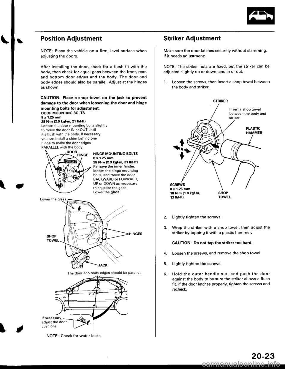
bPosition Adjustment
NOTE: Place the vehicle on a firm, level surface when
adjusting the doors.
After installing the door, check for a flush fit with the
body, then check for equal gaps between the front, rear,
and bottom door edges and the body. The door and
body edges should also be parallel. Adjust at the hinges
as shown,
CAUTION: Place a shop towel on the iack to prevent
damage to the door when loosening the door and hinge
mounting bohs for adiustment.
DOOR MOUNTING BOLTS8 x 1.25 mm28 N.m {2.9 kgf.m.21 lbt'ft}Loosen the door mounting bolts slightly
to move the door lN or OUT until
it's flush with the body. lf necessary,
vou can installa shim behind one
hinge to make the door edgesPARALLEL with the body.
J
HINGE MOUNTING BOLTSI x 1.25 mm28 N.m (2.9 kgf.m,21 lbtft)Remove the inner fender,loosen the hinge mountingbolts, and move the doorBACKWARD or FORWARD,UP or DOWN as necessaryto equalize the gaps.Lower the glass.
\
The door and body edges should be parallel-
ifF t
NOTE: Check for water leaks.
20-23
Striker Adjustment
lvlake sure the door latches securely without slamming.
lf it needs adjustment:
NOTE; The striker nuts are fixed, but the striker can be
adjusted slightly up or down, and in or out.
'L Loosen the screws, then insert a shop towel between
the body and striker.
Insert a shop towelbetween the body and
sc8Ews8 x 1.25 mm18 N.m (1.8 kgf.m,13 tbtftl
PLASTIC
2. Lightly tighten the screws.
3. Wrap the striker with a shop towel, then adjust the
striker by tapping it with a plastic hammer.
CAUTION: Do not tap the striker too hard.
4. Loosen the screws. and remove the shop towel.
Lightly tighten the screws.
Hold the outer handle out, and push the door
against the body to be sure the striker allows a flush
fit. lf the door latches properly, tighten the screws and
recheck.
5.
Page 1303 of 2189
Seats and Seat Belts
Component Location Index
2Dl3Dl1Dl
SHOULDER ANCHOR
ADJUSTER (4D)
(see Page 20-85i
FRONT SEAT BELT
Replacement, Pages 20 85,86
Inspection, Page 20-91
FRONT SEARemoval, Page 20'74
Replacement, Page 20 75
Harness Wiring and Recline
Cable Locations, Page 20-77
Seat Cover RePlacemenl, Page 2O'77
3D:
BEAR SEAT BELTReplacement, Page 20'89Inspection, page 20-91
REAB SEAT BELT (2DI4DI
Replacement, page 20-88
lnspection, page 20-91REAR SEAT EELT BUCKLE/CENTER BELT TONGUE (2DI4DI
(see p6ge 20'90)
REAR SEAT t2Dl4DlRemoval, pages 20-79, 8'l
Seat-back Latch Replacement, page 20-82
Seat Cover RePlacement, Page 20-83
FRONT SEATBELT BUCKLES{see page 20-87)
REAR SEAT BELT BUCKLE/
CENTER BELT TONGUE(see Page 20'90)
REAR SEATRemoval, page 20 80
Seat back Latch Replacement, page 20-8?
Seat Cover RePlacement, Page 20_83
20-73
Page 1309 of 2189
Rear Seat
Removal
NOTE: Take care not to scratch the seat covers and body.
4D:
>: Bolt locationsl_):Hook locations,2
b,,***-,,.1*
D>'
] >mr
;iffiP-"*'piii::#r-,'-, @t,V . se-ri-cusxo" [-6*
v-
2u
2u
SEAT CUSHION
SEAT-BACK
Pivot boll conslruction:
SLITS
lnstallation is the reverse of the removal procedure
PIVOT BOLT ERACKET8 x 1.25 mm22 N m (2.2 kgf m, 16lbtftl
Apply liquid thread lock
NOTE:
. Before attaching the seat-back and seat cushion, make sure there are no twists or kinks in the rear seat belts and
center belt.
. When installing the seat cushion, slip the seat belt buckles through the slits in the seat cushron'
. Make sure the seat-back locks securely.
. lf necessary, adiusr the seat-back latch (see page 20-82) and seat-back (cont'd)
c>,1
6x1.omm l1Q- e "r.o--s.a ru.- tr.o rer-. I s.i N.- ir.o lgr.,i7.2 lbf.ft) ) E 7.2 'tJrftl
:- '/
>: Clip locations, 14
"@rz, \
EEES/
_ _ot /
RIGHT SEATSIDE EOLSTER
CENTEBPIVOTBRACKET
20-79
Page 1311 of 2189
2Dt
>: Bolt locationsa>,6
O : Hook locations. 2 >: Clip location3, 14
SEAT CUSHION
,r@.''----EF-|
EH)w,/
PIVOTBRACKET
BUSXING
PIVOT
PIVOT BOLT BRACKET
I x 1 .25 mm22 N.m (2.2 kgt m. 16lblft)
Apply liquid thread lock.
lnstallation is the reverse of the removal procedure'
NOTE;
.Beforeattachingtheseat-backandseatcushion,makesuretherearenotwistsorkinksintherearseatbe|tsand
center belt.
.wheninsta||ingtheseatcushion,sliptheseatbe|tbucklesthroughthes|itsintheseatcushion.
. Make sure the seat-back locks securely
. lf necessary, adjust the seat-back latch (see page 20-82) and seat-back'
6xr.omm ]9.8 N.m l1.O kgf.m,i,:r:2
B>, 1
ffi
IgIt
c>, 1
6xr.omm I 8r.'r.o-- r22 N.m {2.2 kgtm,' \ffz s.e N.m tr.o *gf.m,'
,r:r",
_) E
7.2rbf.ftl
)
vv
PIVOT BRACKET
RIGHT SEAT.BACK
PIVOT BRACKET
Pivot bolt constauctaon:
TOOTHEDLOCKWASHER
SEAT.BACK MAT
,^
20-41
Page 1312 of 2189
Rear Seat
Seat-back Latch Replacement
2Dl4Dl
Remove the lock cylinder trim, then remove the rear
shelf (see pages 20 59, 61).
NOTE: Take care not to bend each lock rod.
>: Boh, screw locationsA>,4
6x1.0mm9.8 N.m (1.0 kgt.m,7.2 rbf.ftl
LOCK CYLINOERTRIM
.i.-::
LOCKRODS
LEFT SEAT-EACK I-ATCH
Installation is the reverse of the removal procedure.
NOTE:
. Make sure each lock rod is connected securely.. [/ake sure each seat-back locks securely and
opens properly.
. lf necessary, adjust the seat-back latch.
B >,2
/+j
V
LOCKCYLINDER
20-8�2
3D:
Pull the trunk mat away from the seat'back (see page 20-
80).
>: Boll, screw locationsa>,2
6x1.0mm9.8 N.m (1.0 kgf.m,7.2 tbl.ft)
B>, 1
@
LATCH COVEB
Installation is the reverse ofthe removal procedure.
NOTE:
. Replace the released clips with new ones.. lvlake sure the seat-back locks securely and opensproperly.
SEAT"BACK
Page 1313 of 2189

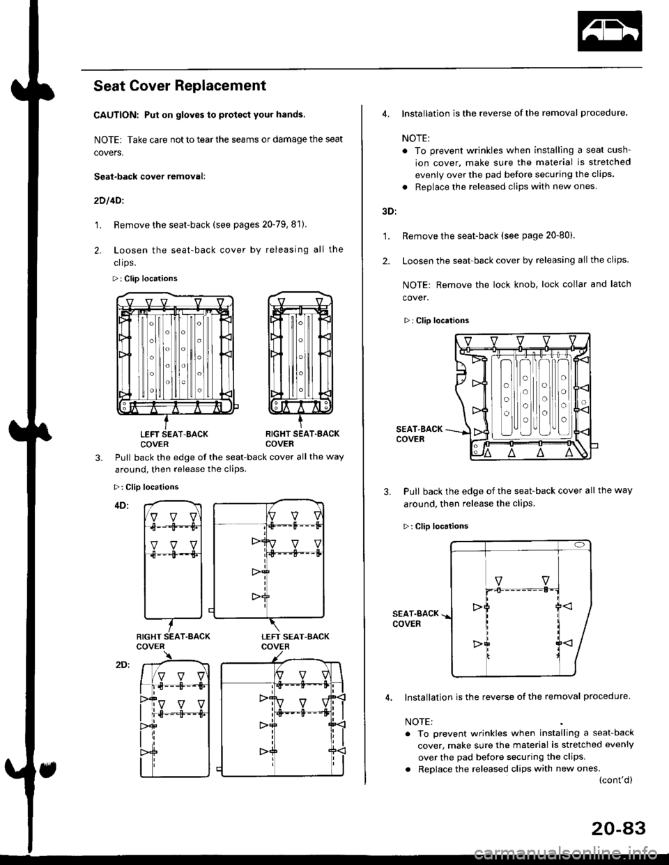
Seat Cover Replacement
CAUTION: Put on gloves to protact your hands,
NOTE| Take care not to tear the seams or damage the seat
covers.
Seat-back cover removal:
2D l4Dl
1. Remove the seat-back (see pages 20-79,8'1).
2. Loosen the seat-back cover by releasing all the
clrps.
>: Clip locations
LEFT SEAT-BACKCOVERRIGHT SEAT.EACKCOVER
3.Pull back the edge of the seat-back cover all the way
around. then release the clios.
>: Clip locations
RIGHT SEAT.BACK
1.
2.
4. Installation is the reverse of the removal procedure.
NOTE:
. To prevent wrinkles when installlng a seat cush-
ion cover. make sure the material is stretched
evenly over the pad before securing the clips.
. Replace the released clips with new ones
3D:
Remove the seat-back (see page 20-80).
Loosen the seat-back cover by releasing all the clips.
NOTE: Remove the lock knob, lock collar and latch
cover.
>: Clip locations
SEAT-BACKCOVER
3. Pull back the edge of the seat-back cover all the way
around, then release the cliPs.
>: Clip locations
SEAT.BACKCOVER
Installation is the reverse of the removal procedure.
NOTE:
. To prevent wrinkles when installing a seat-back
cover, make sure the material is stretched evenly
over the pad before securing the clips.
. Replace the released clips with new ones.(cont'd)
o
o
o
o
o
o
o
o
20-a3