Page 738 of 2189

Electrical Troubleshooting ('96 - 9g Models)
Troubleshooting Flowchart - A/T Gear position Switch (Shortl
NOTE: Record allfreeze data before you troubleshoot.
Poiriblo Caus6
. Short in A/T go.. positionawhch wira. Fauhy A/T goa. position swhch
NOTE: Code P1705 (5)the PCM receives twoinputs at the same time.
is caused whengear position
' OBD ll Scln Toot indic.tes Cod6P1705.. Sofidi.gno3b E indicato] tighrblinksfivatim...
Observo th. A/T Go.r po3ition
Indicator:1. Turn the ignition switch ON l).2. Observe the A"/T gear positionindicator, and shitt to eachposttron,
Do any indicatoG stay onwhen the shift lever is not inthose positions?
Tho sy3tem b OK.t this timo.Check th6 wilc harnari for dam-rga.
M.r.ur. ATP R Vohlge:1. Shift to all positions otherthanE.2. Nileasure the voltage betweenthe 816 and Ag or A22 tormi-nats,
Check for short in tha wirobstwacn the 816 tcrminal and th6A/T go.r porition rwitch or A/Tg..r position indicltor. It wira i3OK, ch.ck for loo!€ FCfit connoc-to13. lf nacetaary, subrtitute aknown€ood Pcllt and roa|rsck.
ls there battery voltage?
Meesur. ATP NP Vohage:1. Shift to allpositions oth€r thanEorE.2. Moasure the voltage betweenthe 825 and A9 or A22 terminats.Check for short in the wireb.tw..n th6 B:I5 torminrt and th.A/T gclr poahion indicator. o. .short in tha wirrs between th.A/T gclr position indicator rndthe A/T gerr poiition switch. lfwir.3 r.o OK, chack tor loosoPCM conn.ctorr. It n.cosarry.sub.tituto a known-good pCM.nd r.chock.M.Gur. ATP D4 Voltago:1. Shift to allpositions otherthanlD.l.2. Measure the voltage betw€enrhe 824 and Ag or A22 termi-nals.
Check tor 3hort in tho wirobc{wocn the 824 terminrl and thoA/T ge.r poiition switch. lI wileia OK, chock tor loo3o plCM con-ncctoaa. It nacossarv, sublthute aknown-good PCM and rech€ck.
ls there approx. 5 V?
PCM CONNECTORS
Wire side of female terminals
YES
To page 14-6':
14-60
Page 739 of 2189
From page 1 4-60PCM CONNECTORS
Wire side ot female terminals
Measuro ATP D3 Voltage:
1. Shift to all positions other than
tr.2. Measure the voltage between
the 88 and A9 or A22 termi-
nals.
Ch.ck tor short in the wire
botwoen tho 88 terminal and ihe
A/T goar position 3witch ol A/T
gosr position indicator, ll wirc is
OK, chock for loo3€ PCM connec-
tor3. lf nece3rary, substituta a
known-good PCM lnd roch€ck
ls there battery voltage?
Morsuro ATP2 Voltage:
1. Shift to all positions other than6t
2. Measurc the voltage between
the 817 and Ag or A22 terml-
n6ls.
Check for short in the wile
b€twesn the B'l 7 terminal and the
A/T ge.r pGition switch or A/T
gear po3ition indicator. lf wire i3
OK, check for loo3o rcM connec'
to13. lf necossarY, substitute a
known-good PICM and recheck.
ls there battery voltage?
check for loose PCM connectors.
lf noc*sarY. sub3titute a known_
good PCM and r.chock.
'96: GRN'97 - 98: PNX
B (25P1
14-61
Page 740 of 2189

Electrical Troubleshooting ('96 - gg Modelsl
Troubleshooting Flowchart - A/T Gear position Switch (Open)
. OBD ll Scan Tool indicates CodeP1706.. Self-di.gnosk E indicator tightblinks six timos.
Measure ATP 04 Voltege:1. Shiftto E position.2. Measure the voltage betweenthe 824 and A9 or A22 terminals,
ls there voltage?
Possible Causo
. Disconnected A/T gear positionswitch conn€ctor. Open in A/T gear positionswitch wire. Faulty A/T gear position switch
Wire side of female terminals
NOTE: Record all freeze data before you troubleshoot.
Moasure ATP I Voltage:1. Turn the ignition switch ON 1 ).2. Shift to E position.3. Measure the voltage betweenthe B'f6 and Ag ot A22 tetmi-nats.
Ropai. op€n in the wire betwe€nthe Bl6 terminal.nd the A/T gearposition swhch.
Measur€ ATP NP Voltage:1. Shift to E or E position.2. Measure the voltage betweenthe 825 and A9 or A22 termi,nals,
Repeir open in the wir€ betweentho B25 terminal and th6 A/T geerposition indicator or tho A/T 96.rposition 3witch.
Rcpair open in the wire betweentto 82{ to.minal and th6 A/T geatlrosition 3witch.
To page 14 63
PCM CONNECTORS
NO
1
L
+62
Page 753 of 2189

Troubleshooting Flowchart - Shift Control System
NOTE: Record all freeze data before vou troubleshoot.
Possible Cause
Faulty shift control system
. OBD ll Scan Tool indicates CodeP0730.. Sell-diagnosis E indicator
light indicates Code ill.
Check tor Another CoderCheck whether the OBD ll scantool or the E, indicator lightindicate another code.
Perlorm ths TroubleshoolingFlowch.rt for the indic.t.dCode(sl. Recheck tor code m730
l4'l I atter troubleshooting.
Does the oBD ll scan tool orthe E indicato'. tight indicate another code?
Test lst, 2nd, 3rd and 4th Clutch
Pressure:Measure the 1st, 2nd, 3rd and 4th
clutch pressure (see page 14119
thru 14-121).
Ropair the hydrlulic systom !snecessary {see page 14-1 19 and11-1211.
ls each clutch pressure within
the service limit?
Replace Shift Control Solenoidvalve Assembly, Linear SolenoidAssambly and Rechock:1. Replace the shift controlsolenoid valve A'/B assembly(see page 14-106).2. Replace the linear solenoidassembly lsee page 14 108).3. Turn the ignition switch OFFand reset the PCM memory byremoving the EACK UP (7.5 A)tuse in the under hood fuse/relay box for more than l0
seconds,4. Drive the vehicle at over 12mph (20 km/h) in 1st, 2nd,3rd
and 4th gear for more than 30seconds at P1 position.
5. Recheck tor code P0730 (41).
Does the OBD ll scan tool orthe Ed indicator tight indi
cate code P0730 {41)?
The swt6m is OK et this time.
NOTE: Do not continue with this troubleshooting until the causes ot any
other DTCS have been corrected.
Page 762 of 2189

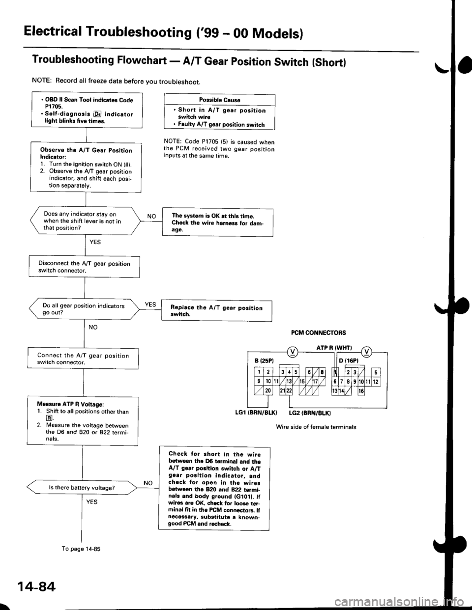
Electrical Troubleshooting ('gg - 00 Models)
Troubleshooting Flowchart - A/T Gear position Switch (Short)
NOTE: Record all freeze data before you troubleshoot.
Po$ible Cause
' Short in A/T go.r positionswhch wire. Faulty A/T goar position switch
NOTE: Code P1705 (5)the PCM received twoinputs at the same time.
is caused whengear position
PCM CONNECTORS
LGl (BRN/BLK) LG2 (BRN/BLKI
Wire side of femaleterminals
B {25P1 llD (16P1
. OBD ll Scan Tool indicrtB CodeP1?05.. Solt-diagno3i3 E indicatorlight blink. tive times.
Observo the A/T Gear PositionIndicetori1. Turn the ignition switch ON fit).2. Observe the lVT gear positionindicator, and shift each posi,!on separately.
Does any indicator stay onwhen the shift lever is not inthat position?
The sFtom is OK at thi3 time.Check the wi.e harness for dam-aga.
Do all gear position indicatorsgo out?
Moasure ATP R Voltage:1. Shift to all positions otherthanE.2. Measure the voltage betweenthe DG and 82O o( 822 terfii-nats.
Check tor short in the wirebatwoen tha DB terminal and theA/T go.r porhion switch or A/Tg6ar po3ition indicator, andchock for opon in the wiresbetween the B20 and B22 t€rmi-n.ls and body ground (G10 . tfwir€c rro OK, chsck fo. loo3e tel-ftinal fit in the FCM connectors. llnoceisary, substiiute e known-good FCM and r€check.
ls there battery voltage?
To page 14-85
\
14-84
Page 764 of 2189
ElectricalTroubleshooting ('gg - 00 Models)
Troubleshooting Flowchart - A/T Gear position Switch (Short) (cont,dl
LGl (BRN/BLK}
FCM CONNECTORS
B {25P)D l16Pl
12[Ll81235
9101/113/ 151/)11789t0112,/ 20
ATP 2 {BLUI
Wire side of female terminals
Measule ATP 2 Vohage:1. Shift to all positions other thanl
2. Measure the voltage betweenthe D14 and 820 or 822 termi-nals,
Check for short in the wirebetween the D14 terminal andthe A/T gear position switch orA/T ge.r position indicator. Itwires aae OK, check loa loose ter-minal th in ths PCM connectors. llnecessary, substitute a known-good FCM and recheck.
ls there battery voltage?
Ch6ck for loose terminal fit in thePCM connoctors. lf necessary,substitute a known-good PCMand recheck.
\
14-86
Page 765 of 2189

Troubleshooting Flowchart - A/T Gear Position Switch (Open)
NOTE: Record allfreeze data before you troubleshoot.
Po$ible Cause
. Disconnectod A/T goar position
switch conngdor. Open in A/T gear position
switch wire. Fautty Aft gear poshion switch
PCM CONNECTORS
Wire side of lemaleterminals
D (16P1
GRNI
B (25Pt llDtl6Pl
IARN/BLK) LG2IBRN/BLKI
2{6,|235
I't011/t5l/18912
ATP NP (LT
. OBO ll Scan Tool indicatd CodcP1706.' Sslf-diagnosis E indicatorlight blink3 six tim6.
Test the Ay'T gear position switch(see section 23).
Moasure ATP R Volt.ge:'1. Turn the ignition switch ON ('l).
2. Shift to E position.
3. Measure the voltage between
the D6 and 820 ot 822 termi'nals.
Repoir opon in the wire bitween
the D6 torminll and the A/T go.r
position switch.
Measuro ATP NP Volt ge:
1. Shift to E or E position.
2. Measlre the voltage betweenthe D13 and 820 or 822 termi-nals,
Ropair op€n in thc wire betwoonthe D13 terminrl and the A/Tge.r position switch.
LG1 {BBN/BLKI
Io page 14-88
(cont'd)
Page 778 of 2189

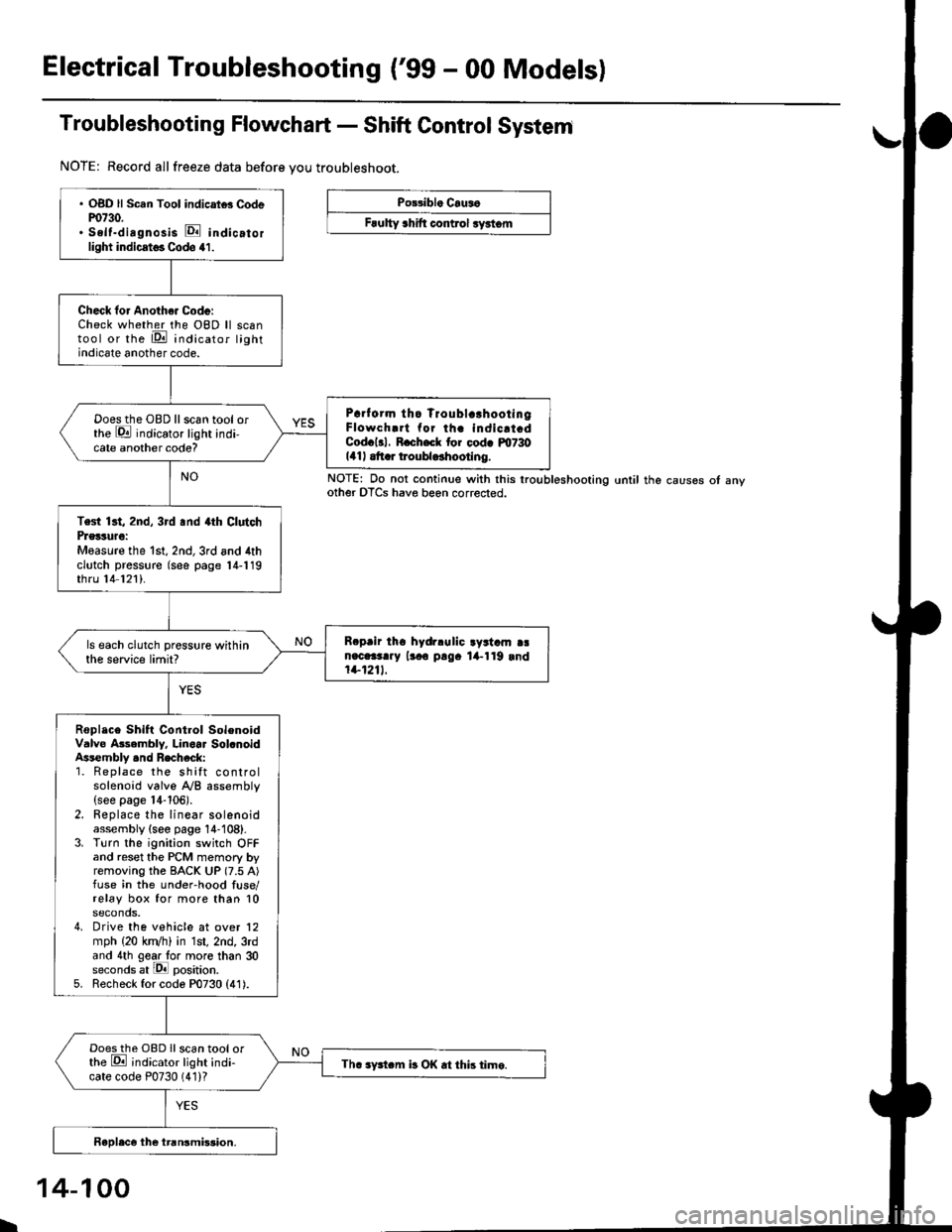
Electrical Troubleshooting ('99 - 00 Modelsl
Troubleshooting Flowchart - Shift Control System
NOTE: Record allfreeze data before you troubleshoot.
Po33ibl. Crus6
Frulty 3hift control ryrtom
. OBD ll Scan Tool indicrtd Codem730.. Self-dirgnosis E indicatorlight indicst€. Codo 41.
Check for Anoth€. Code:Check whether the OBD ll scantool or the E indicator lightindicate another code.
Prrf orm tho Troublc!hootingFlowch.rt for th. indicrt.dCod.l3l. R.ch.ck tor cod. m730141| .tt r troubldhootlng.
Doesthe OBD llscan tool orthe E indicator light indi-cate another code?
Test 13t, 2nd, 3rd .nd 4th ClutchPrglture:Measure the 1st, 2nd,3rd and 4thclutch pressure (see page 14-119thru 14 121).
R.prir tho hydrlulic ayrtam aan.c.3t..y lr.o p!9. lil-119 rnd1+1211.
ls each clutch pressure withinthe service limit?
Roplace Shift Control SolenoidValve Asembly. Linoar Sol.noidAssembly .nd Recheck:1. Replace the shift controlsolenoid valve A/B assembly(see page 14-106).2. Replace the linear solenoidassembly {see page 14-108}.3. Turn the ignition switch OFFand reset the PCM memory byremoving the BACK UP (7.5 A)fuse in the under-hood fuse/relay box for more than 10seconds,4. Drive the vehicle at over 12mph (20 kn/h) in 1st, 2nd, 3rdand 4th gear lo. more than 30seconds at lPll position.5. Recheck for code P0730 (41).
Doesthe OBD Ilscan tool orthe E ;ndicator light indi-cate code P0730 (41)?Th. sFtcm b OK .t this time.
NOTE: Do not continue with this lroubleshooting until the causes ot anyother OTCS have beon corrected.
I
14-100