1998 HONDA CIVIC Water reservoir
[x] Cancel search: Water reservoirPage 257 of 2189
lllustrated Index
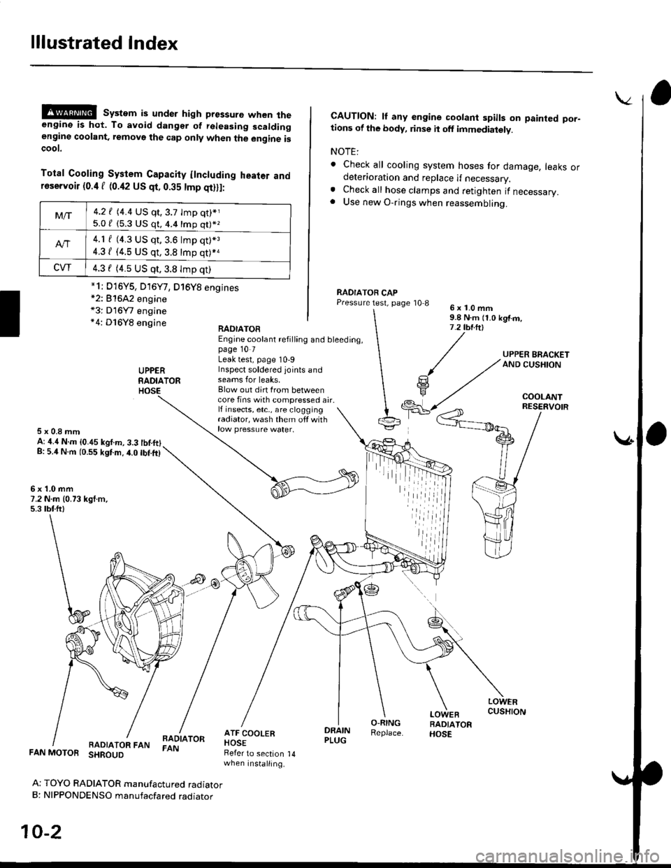
@@ system is under high pressure when theengine is hot. To avoid dangsr of rsleasing scaldingengine coolant, removo the cap only when the engine iscoot.
Total Cooling System Capacity flncluding heater andfoservoir (0.4 f (0.42 US qt, 0.35 tmp qt)ll:
*2: 81642 engine*3: D16Y7 engine*4: D16Y8 engine
CAUTION: lf any engine coolant spills on painted por-tions of the body, rinse it off immediately.
NOTE:
. Check all cooling system hoses for damage, leaks ordeterioration and replace if necessary.. Check all hose clamps and retighten if necessary.. Use new O-rings when reassembling.
RADIATOR CAPPressure test, page '10 86x1.0mm9.8 N.m {1.0 kgtm,7.2 tbt.ltl
UPPERRADIATORHOSE
UPPER BRACKETAND CUSHION
COOLANT
RAOIATOREngine coolant refilling and bleeding,page 10 7Leak test, page 10-9Inspect soldered joints andseams for leaks,Blow out dirt Irom betweencore fins with compressed air.lf insects, etc,, are cloggingradiator, wash them off withrow pressure water.
RESERVOIR
5x0.8mmA: ,1.4 N.m {0.45 kgf.m, 3.3 tbtftlg: 5.4 N.m (0.55 kgtm.4.0 tbf.ft)
6x1.0mm7.2 N.m (0.73 kgt.m,5.3 tbtftl
LOWERCUSHION
RADIATOR FANBADIATORFAN
DRAINPLUG
O-RINGReplace.
LOWEBRADIATORHOSE
FAN MOTOR SHROUD
Ar TOYO RADIATOR manufactured radiatorB: NIPPONDENSO manufacfared raoraror
10-2
Refer to section 14when installing.
Mt-|-4.2 f (4.4 US qt,3.7 tmp qt)*j
5.0 / (5.3 U$ q1, 4.4 16p q11*z
4.1 f (4.3 US qt, 3.6 lmp q0*3
4.31 (4.5 US qt, 3.8 tmp qt)*a
CVT4.3 f (4.5 US qt,3.8 Imp qt)
*1i D16Y5, D16Y7, D16Y8 engines
iil
Page 262 of 2189

tl
Engine Coolant Refilling and Bleeding
CAUTION: when pouring engine coolant, be sure to
shut the relay box lid and not to lst coolant spill on the
eleqtrical parts or the paint. lf any coolant spills, rinse it
off immediately.
1. Slide the heater temperature control lever to maxl-
mum heat. Make sure the engine and radiator are
cool to the touch.
Remove the radiator caP.
Loosen the drain plug, and drain the coolant'
Remove the drain bolt from the cylinder block'
D16Y5. D16Y7, Dl6Yg sngines:
DRAIN PLUG
0d
I ro
78 N.m {8.0 kgl m.58lbt'ft)
6.
1.
B1642 engin€:
WASHERReplace.
DRAIN BOLT78 N m (8 0 kgf m' 58lbfft)
Apply liquid gasket to the drain bolt threads, then
reinstall the bolt with a new washer and tighten 't
securely.
Tighten the radiator drain plug securely
Remove, drain and reinstall the reservoir' Fill the
tank halfway to the MAX mark with water, then up
to the MAX mark with antitreeze.
(cont'd)
10-7
MAX MARK
Page 263 of 2189
Radiator
Engine Coolant Refilting and Bleeding (cont,dl
8. Mix the recommended antifreeze with an eoualamount of water in a clean container.
NOTE:
o Use only genuine Honda antifreeze/coolant.. For best corrosion protection. the coolant con_centration must be maintained year_round at50% minimum. Coolant concentrations less than50% may not provide sufficient protectionagainst corrosion or freezing.. Coolant concentrations greater than 60010 willimpair cooling efficiency and are not recom_mended.
CAUTION:
. Do not mix difforont brands ofar ilreeze/coolants.. Do not use additional rust inhibiiors or anti_rustproduqt3; they may not be compatible with thecoolant.
Engine Coolent Refi
Capacity Iincluding reservoir{0.4 f 10.42 US qr, 0.35 lmp qt),I;
*1: D16Y5, D16Y/, O16Y8 engines*2: 81642 engine*3; Dl6Y7 engine*4: Dl6Y8 engine
M/r3.8 f {4.0 US qt, 3.3 lmp qt)*1
4.5 / (4.8 US qt. 4.0 tmp qt)*,
Att3.7, (3.9 US qr,3.3 tmp qt).3
3.9 / (4.1 US qt,3.4lmp qt)*.
CW3.9 / (4.1 US qt,3.4 tmp qtl
10-8
\.-I
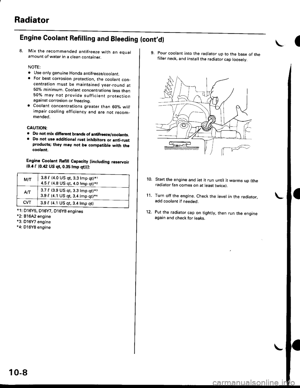
9. Pour coolant into the radiator up to the base of thefiller neck. and install the radiator cap looselv.
Start the engine and let it run until it warms up (theradiator fan comes on at least twicer.
Turn off the engine. Check the level in the radiator.add coolant if needed.
Put the radiator cap on tightly, then run the engineagain and check for leaks.
10.
11.
Page 572 of 2189
Glutch Master Gylinder
IRemovaUlnstallation
CAU'NON:
. Do not sDill brake lluid onthevehicle;it may damage
the paint; if brake fluid does contact the paint, wash
it off immediatelY with water.
. Plug the end ofthe clutch line and reservoir hos€ with
a shop towelto prevent brake tluid from coming out
1. The brake tluid can be removed from the clutch
master cylinder reservoir with a syringe
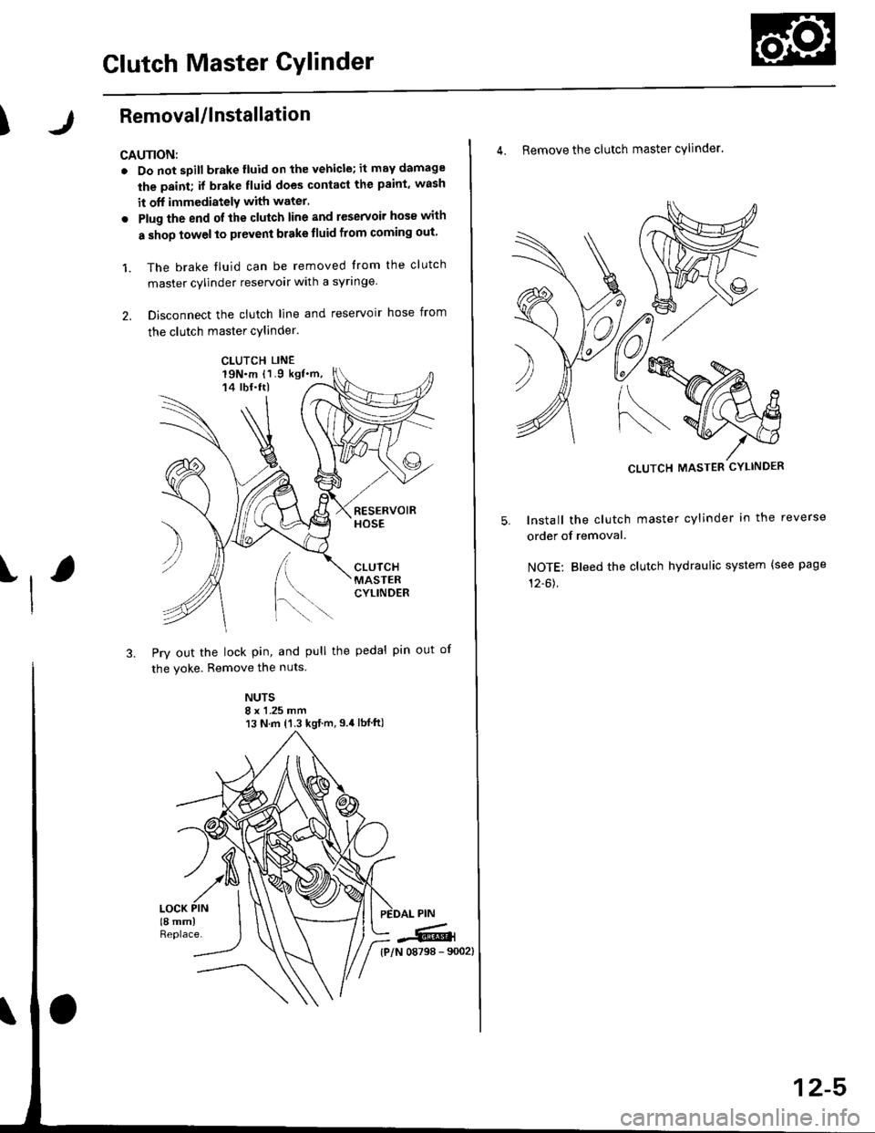
2. Disconnect the clutch line and reservoir hose from
the clutch master cylinder.
19N.m 11.9 kgf.m,14 tbf.ttl
[.
3. Pry out the lock pin, and pull the pedal pin out
the yoke. Remove the nuts
NUTS8 x 1 .25 mm13 N.m {'1.3 kgt.m,9.4lbf ft)
)
of
CLUTCH LINE
iffi,
4. Remove the clutch master cylinder.
CLUTCH MASTER CYLINDER
lnstall the clutch master cylinder in the reverse
order of removal.
NOTE: Bleed the clutch hydraulic system {see page
12-61,
12-5
Page 1161 of 2189
I
Bleeding
CAUTION:
. Always use Genuine Honda DOT 3 Brake Fluid. Using 8
non-Honda brak€ fluid can cause corrosion and
docrea3e the life of the system.
. Make surs ||o dirt or other foteign matter is allowed
to contaminate the brake fluid,
. Do not spill brake lluid on the vehicle, it may damago
the paint; if brake lluid doos contac{ the paint, wash
it ofl imm€diately with water.
NOTE: The reservoir on the master cylinder must be at
the MAX (upper) level mark at the start of the bleeding
procedure and checked after bleeding each brake
caliper. Add fluid as required.
1. Make sure the brake fluid level in the reservoir is at
the MAX lupper) level line.
MAX {UPPER) LEVEL
CYLINDER
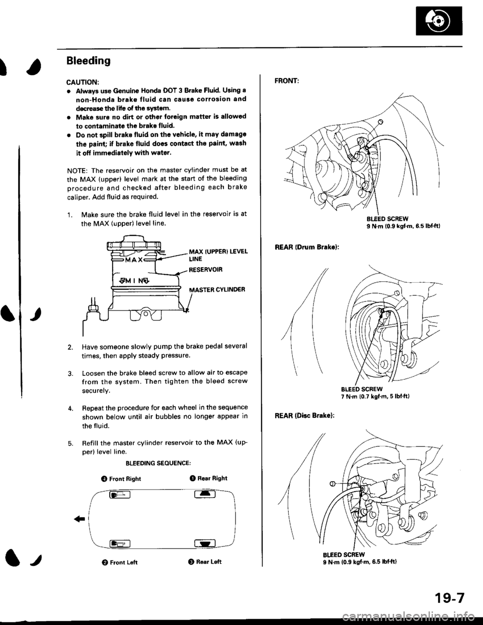
Have someone slowly pump the brake pedsl several
times, then apply steady Pressure.
Loosen the brake bleed screw to allow air to escape
from the system. Then tighten the bleed screw
securely.
Repeat the procedure for each wheel in the sequence
shown below until air bubbles no longer appear in
the fluid.
Refill the master cylinder reservoir to the MAX (up-
per) level line.
ELEEDING SEOUENCE:
O Front Right(D Bo.r Right
O Front LeftO Rear Left1,,
19-7
FRONTT
REAR lDrum Brakel:
REAR (Disc Brake):
AIEED SCREW9 N.m (0.9 ksf m, 6.5 lbf'ft)
Page 1175 of 2189
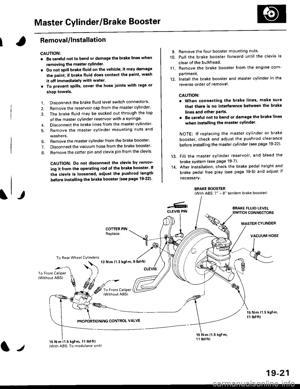
Master Cylinder/Brake Booster
IRemovaUlnstallation
CAUTION:
. Be care{ul nol to bend or damage the brake lines when
rsmoving the mastsr cYlinder.
. Do not soill brakefluid on the vehicle; it may damage
the paint; if brake fluid does contact the paint, wssh
it off immediatelY with water'
. To prevent spill3, cover the hose ioints with rags or
shop towels.
9. Remove the four booster mountlng nuts
10. Pull the brake booster forward until the clevis is
clear of the bulkhead.
11. Remove the brake booster from the engine com-
panmenr.'12. Install the brake booster and master cylinder in the
reverse order of removal.
CAUTION:
. When connecting the brake lines. make sure
that there is no inte erence between the brake
lines and oth6r Parts.
r Be careful not to bend or damage the brake lines
when installing the master cylinder.
NOTE: lf replacing the master cylinder or brake
booster, check and adiust the pushrod clearance
be{ore installing the master cylinder (see page 19-221'
Fill the master cylinder reservoir, and bleed the
brake svstem (see Page 19-7).
After installation. check the brake pedal height and
brake pedal tree play (see page l9-5) and adjust if
necessary.
BRAKE BOOSTER(With ABS: 7" + 8" tandem brake booster)
BRAKE FLUIO LEVELSWITCH CONNECTORS
MASTER CYLINDER
VACUUM HOSE
1.
2.
3,
5.
Disconnect the brake fluid level switch connectors'
Remove the reservoir cap from the master cylinder'
The brake fluid may be sucked out through the top
of the master cylinder reservoir with a syrlnge.
Disconnect the brake lines from the master cylinder'
Remove the master cylinder mounting nuts and
washers.
\l/
6. Remove the master cylinder from the brake booster'
7. Disconnect the vacuum hose trom the brake booster'
8. Remove the cotter pin and clevis pin from the clevis'
CAUTION: Do not disconnect the clevb by remov-
ing it from the operating rod of the brako booster' lf
the clevis is loosened, adiust the pushrod length
before installing th€ brake booster (see page 19-221'
COTTER PINReplace.
To Rear Wheel Cylinders
14.
-6.4CLEVIS PIN
To Front Caliper(Without ABS)$
t'N't'ttrnt'-''
To Front CaliperlWithout ABSi
PBOPORTIONING CONTROL VALVE
15 N.m {1.5 kgl m,11 tbtft)
15 N.m {1.5 kgif.m, 11 lbtft}(With ABS: To modulator unit)lr
19-21