1998 HONDA CIVIC Valve clearance
[x] Cancel search: Valve clearancePage 112 of 2189
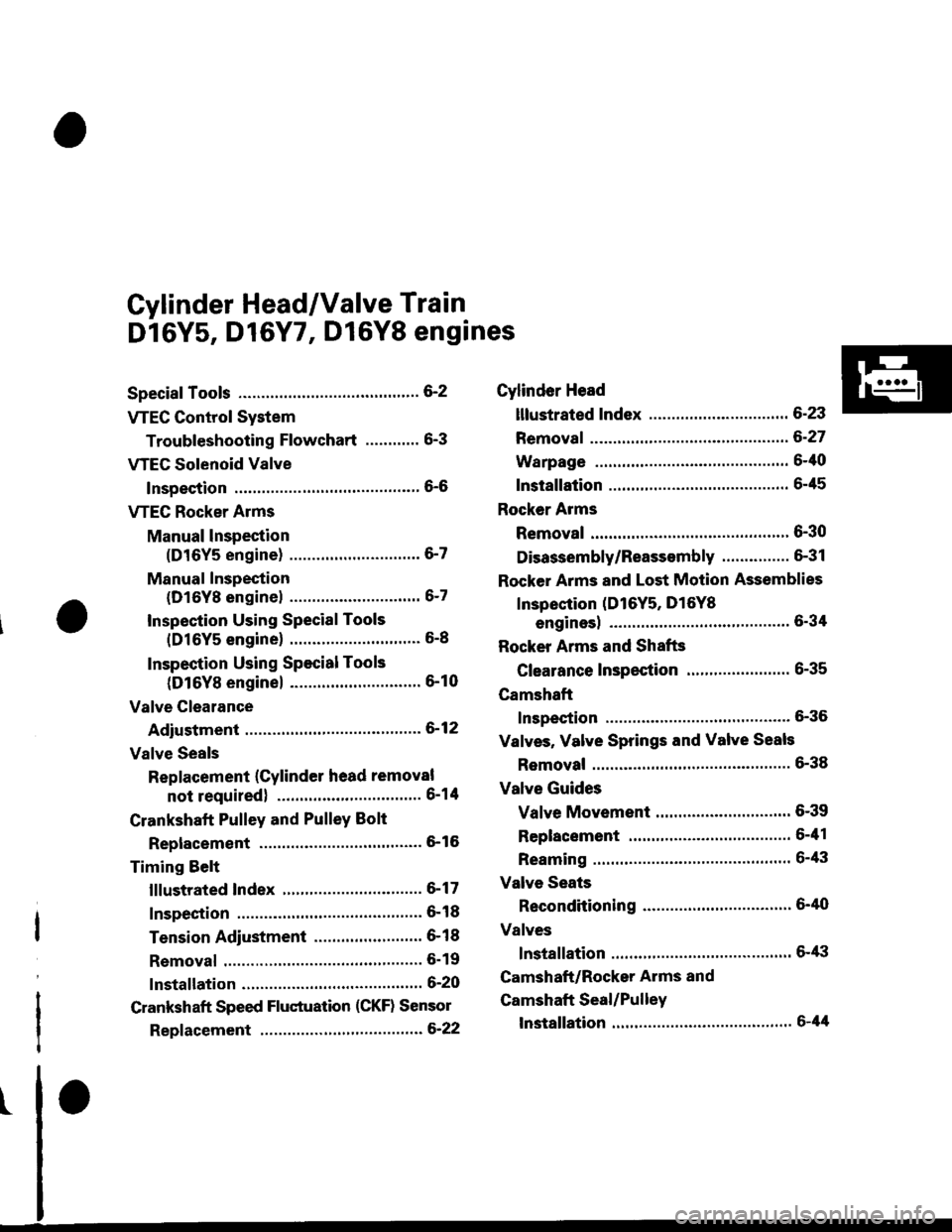
Cylinder Head/Valve Train
Dl6Y5, D16Y7, Dl6Y8 engines
Special Tools ............. G2
VTEC Control System
Troubleshooting Flowchart .........." 6-3
VTEG Solenoid Valve
Inspection ............" 6-6
VTEC Rocker Arms
Manual lnspection
(D16Y5 engine) ............................. 6-7
Manual Inspection
(D16Yg enginel ................'............ 6-7
Inspection Using Special Tools
{D16Y5 engine} .....................""'... 6-8
Inspection Using Special Tools
(D16Y8 engine) .........................'.'. 6-10
Valve Clearance
Adiustment ..."".....6-12
Valve Seals
Replacement (Cylinder head removal
not requiredl ................................ 6-1tl
Crankshaft Pulley and PulleY Bolt
Replacement ."...... &16
Timing Selt
lllustrated Index ............................... 6-17
Inspection .............. 6-18
Tension Adjustment ........................ 6- 1 I
Removal ......,,......... 6-19
lnstallation ............. 6-20
Crankshaft Speed Fluctuation (CKF) Sensor
Repf acement .........6'22
Cylinder Head
lllustrated Index ............................... 6-23
Removal ................. 6-27
Warpage ................ 6-40
lnstallation ............. 6-45
Rocker Arms
Removal ................. 6-30
Disassembly/Reassambly ............... 6-31
Rocker Arms and Lost Motion Assemblies
Inspection (D16Y5, D16Yg
enginesl "..........' 5-34
Rocker Arms and Shafts
Glearance Inspection ....................... 6-35
Camshaft
Inspection .............. 6-36
Valves, Valve Springs and Valve Seals
Removal ........""..... 6-38
Valve Guides
Valve Movement .............................. 6-39
Replacement .........6-41
Reaming .......'......'.' 6-43
Valve Seats
Reconditioning .'....6'40
Valves
lnstallation ............. 6-tt3
Camshaft/Rocker Arms and
Camshaft Seal/Pulley
lnstallation ............. 6-44
Page 119 of 2189
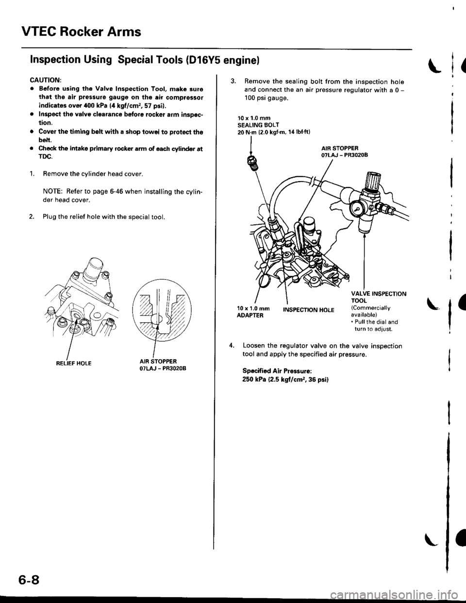
VTEC Rocker Arms
Inspection Using SpecialTools (Dl6Y5 enginel
CAUTION:
. Before using th6 Valve Inspection Tool, make 3ure
that ths air pressure gaugo on the air comptsssor
indicates over iloo kPa 14 kgf/cmr, 57 psi).
. Inspecl th6 valv€ clearance beforo rocker atm insDec"
tion,
'1.
Cover the timing belt with a shop towel to protect tho
belt.
Check ths intakg primaty rocker arm of each cylindqr atTDC.
Remove the cylinder head cover.
NOTE: Refer to page 6-46 when installing the cylin-
der head cover.
Plug the relief hole with the special tool.
YY
OTLAJ - PR3O2OB
(
3, Remove the sealing bolt from the inspection holeand connect the an air pressure regulator with a 0 -
100 psi gauge.
10 x 1.0 mmSEALING BOLT20 N.m {2.0 kgj'm. 14lblft}
l
I
'10 x 1.0 mmADAPTER;NSp€CTTONHOLE (Commercially
available)
l'Pullthe dial andturn to adlust,
Loosen the regulator valve on the valve inspection
tool and apply the specified air pressure.
Spocified Air Pressurei
250 kPa {2.5 kg,t/cm,,36 psi}
o-at
Page 123 of 2189
Valve Clearance
Adjustment
NOTE:
. Valves should be adjusted only when the cylindsrhead temperature is less than 100"F (38"C).
. After adjusting, retorque the crankshaft pulley bolt(see page 6-16).
1, Remove the cylinder head cover.
NOTE; Refer to page e46 when installing the cytinderhead cover.
2. Remove the upper cover (see page 6-19).
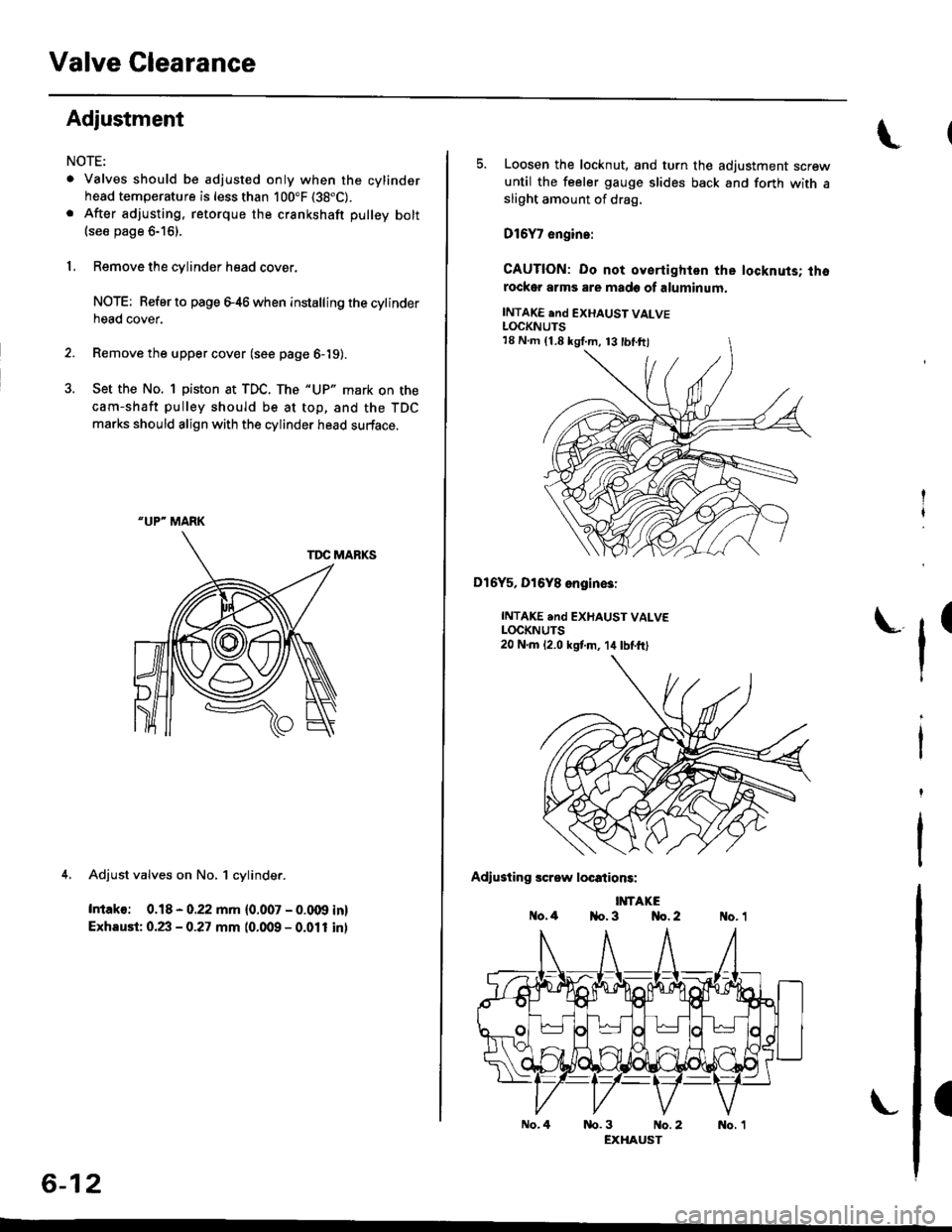
3. Set the No. 1 piston at TDC. The "UP" mark on the
cam-shaft pulley should be at top, and the TDC
marks should align with the cylinder head surface.
TDC MARKS
4. Adjust valves on No, 1 cylinder.
Intako: 0.18 - 0.22 mm {0.007 - 0.009 in}
Exhaust: 0.23 - 0.27 mm (0.009 - 0.011 inl
"UP" MARK
6-12
No.4
5. Loosen the locknut, and turn the adjustment screwuntil the feeler gauge slides back and forth with asliOht amount of drag,
D16Y7 engin.:
CAUTION: Do not oyertighlen the locknuts; thorockor arms are made of aluminum.
INTAKE end EXHAUST VALVELOCKNUTS
Dl6Y5, Dl6Y8 engin€3:
INTAKE .nd EXHAUST VALVELOCKNUTS20 N.m 12.0 kstm, 14lbtft)
Adiusting screw locations:
IMTAKEo.4 1{o. 3 No. 2
tr'
(
nb.3 No.2 No. 1EXHAUST
18 N.m (1.8 kgI.m, 13 tbl.ftl
Page 124 of 2189

6. Tighten the locknut, and check the clearance again.
Repeat the adjustment if necessary.
GAUGE
7.Rotate the crankshaft 180' counterclockwise (cam-
shaft oullev turns 90'1. The "UP" mark should be on
the exhaust side. Adjust valves on No. 3 cylinder.
"UP- MARK
t
8. Rotate the crankshaft '180' counterclockwise to
bring No.4 piston to TDC. Both TDC grooves are
once again visible. Adjust valves on No. 4 cylinder.
Rotate the crankshaft 180'counterclockwise to bring
No. 2 piston to TDC. The "UP" mark should be on
the intake side. Adjust valves on No. 2 cylinder.
-UP'MARK
6-13
Page 150 of 2189
Valve Guides
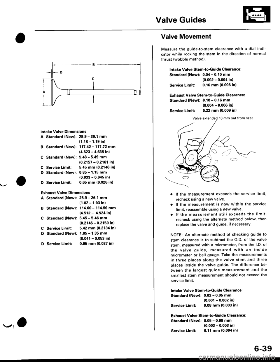
lntake Valve Dimensions
A Standsrd lNewl: 29.9 - 30.1 mm
B Standard (New):
C Standald {Newl:
C Service Limit:
D Standard (New):
D Service Limit:
11.18 - 1.19 inl
117.42 - 117.72 mm
(4.523 - 4.635 inl
5.'18 - 5.49 mm
{0.2r57 - 0.2r61 in)
5.,[5 mm (0.21,16 in]
0.85 - 1.15 mm
(0.033 - 0.0'15 in)
0.65 mm (0.026 in)
Exhaust Valve Dimensions
A Standard lNew): 25.9 - 26.1 mm
B Standard {Newl:
C Standard {New):
C Service Limit:
D Standard {New):
D Service Limit:
(1.02 - 1.03 in)
114.60 - 114.90 mm
11.512 - 4.521in1
5.i[5 - 5.46 mm
10.21lt6 - 0.2150 inl
5.,12 mm 10.213'l in)
1.05 - 1.35 mm
{0.041 - 0.053 in)
0.95 mm {0.037 in}
Valve Movement
Measure the guide-to-stem clearance with a dial indi-
cator while rocking the stem in the direction of normal
thrust (wobble method).
lniake Valve Stem-to-Guide Clearance:
St8ndard lNew): 0.04 - 0.10 mm
10.002 - 0.004 in)
Service Limit: 0.16 mm 10.006 in)
Exhaust Valvs Stem-to-Guide Glearance:
Standard {New}: 0.10 - 0.16 mm
10.004 - 0.006 in)
Sorvice Limit 0.22 mm (0.009 in)
O/'-_)
. lf the measurement exceeds the service limit,
recheck using a new valve.
. lf the measurement is now within the service
limit, reassemble using a new valve.
. lf the measurement still exceeds the limit,
recheck using the alternate method below, then
replace the valve and guide, if necessary.
NOTE: An alternate method of checking guide to
stem clearance is to subtract the O.D. of the valve
stem, measured with a micrometer, from the l.D. of
the valve guide, measured with an inside
micrometer or ball gauge. Take the measurements
in three places along the valve stem and three
places inside the valve guide. The difference be-
tween the largest guide measurement and the
smallest stem measurement should not exceed the
service limit.
lntake Valve Stgm-to-Guidg clearance:
Standard {Newl: 0.02 - 0.05 mm
{0.001 - 0.002 in)
Ssrvico Limit 0.08 mm (0.003 in)
Exhaust Valvo Stem-to-Guide Clearance:
Standard {New): 0.05 - 0.OB mm
{0.002 - 0.003 in)
S€rvice Limit 0.11 mm (o'Ooil in)
Valve extended 10 mm out from seat.
6-39
Page 151 of 2189
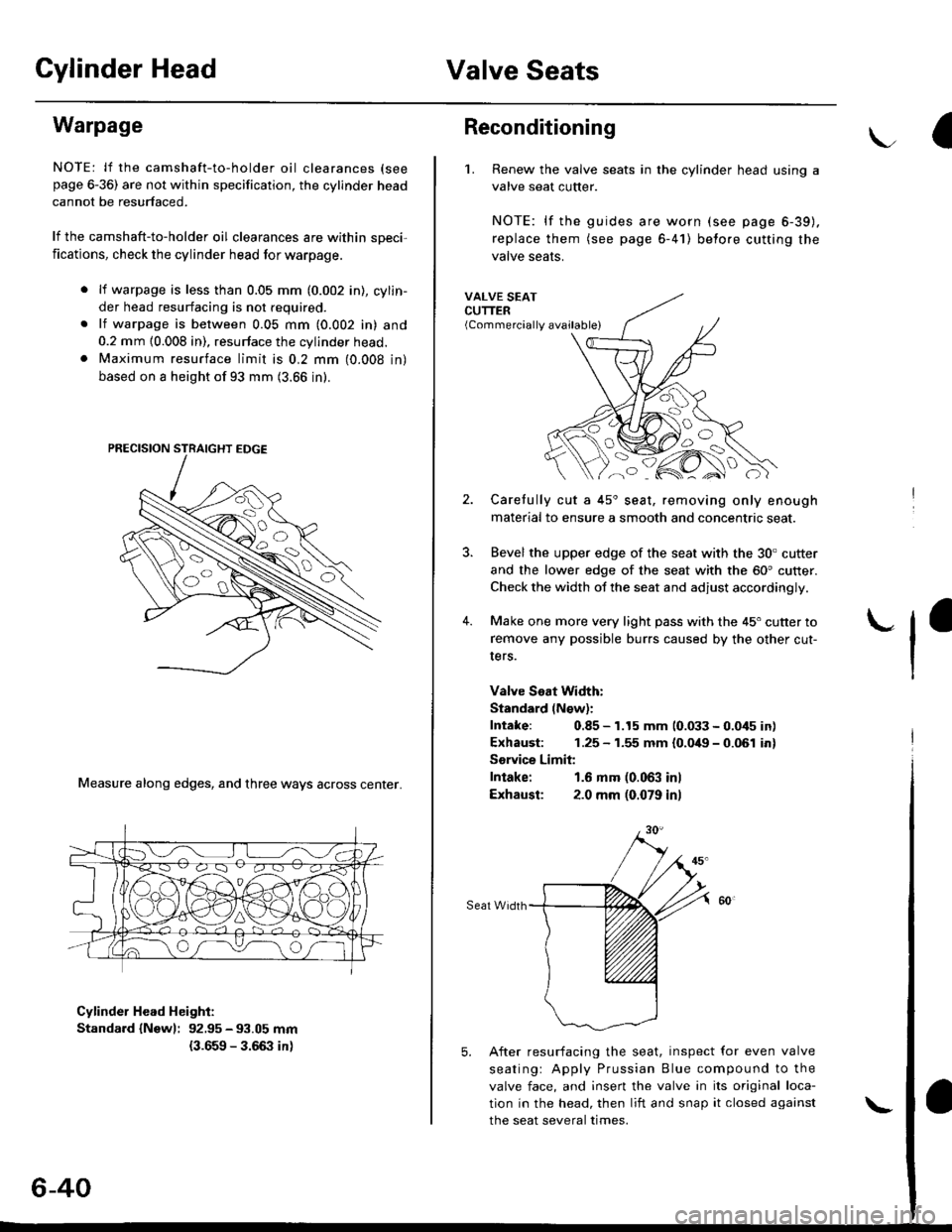
Cylinder HeadValve Seats
Warpage
NOTE: lf the camshaft-to-holder oil clearances (see
page 6-36) are not within specification, the cylinder head
cannot be resurfaced.
lf the camshaft-to-holder oil clearances are within sDeci,
fications, check the cylinder head lor warpage.
lf warpage is less than 0.05 mm (0.002 in), cylin-
der head resurfacing is not required.
lf warpage is between 0.05 mm (0.002 in) and
0.2 mm {0.008 in), resurface the cylinder head.
Maximum resurface limit is 0,2 mm (0.008 in)
based on a height of 93 mm (3.66 in).
Measure along edges, and three ways across center.
Cylinder Head Height:
Standard {Newl: 92.95 - 93.05 mm
{3.659 - 3.66:} in)
6-40
\
Reconditioning
'1. Renew the valve seats in the cylinder head using a
valve seat cutter.
NOTE: lf the guides are worn (see page 6-39).
replace them (see page 6-41) belore cutting the
valve seats.
VALVE SEATCUTTER(Commercially available)
2.
?
4.
Carefully cut a 45'seat, removing only enough
material to ensure a smooth and concentric seat.
Bevel the upper edge of the seat with the 30. cutter
and the lower edge of the seat with the 60' cutter.
Check the width of the seat and adjust accordingly.
Make one more very light pass with the 45" cutter to
remove any possible burrs caused by the other cut-
Iers.
Valve Seat Width:
Standard (N€w):
Intake: 0.85 - 1.15 mm 10.033 - 0.045 in)
Exhaust: 1.25 - 1.55 mm {0.049 - 0.061 in}
Sorvice Limit:
Intake: 1.6 mm (0.063 inl
Exhausl: 2.0 mm (0.079 in)
Seat Width
5. After resurfacing the seat, inspect for even valve
seatingr Apply Prussian Blue compound to the
valve face, and insert the valve in its original loca-
tion in the head, then liit and snap it closed against
the seat several times.
Page 154 of 2189
Valves
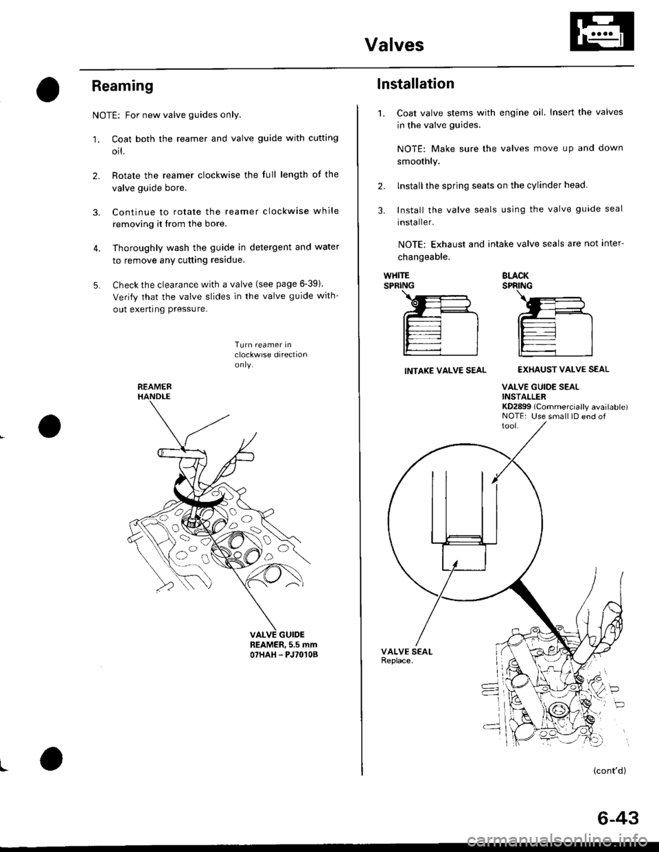
Reaming
NOTE: For new valve guides only.
1. Coat both the reamer and valve guide with cufting
orl.
2. Rotate the reamer clockwise the full length of the
valve guide bore.
3. Continue to rotate the reamer clockwise while
removing it from the bore.
4. Thoroughly wash the guide in detergent and water
to remove any cutting residue.
5. Check the clearance with a valve (see page 6-391.
Verify that the valve slides in the valve guide with-
out exerting Pressure.
Turn reamer inclockwise direclionon ly.
REAMER, 5.5 mmO7HAH. PJ'O'IOB
I
REAMER
oa)o,
o
o
1.
lnstallation
Coat valve stems with engine oil. Insert the valves
in the valve guides.
NOTE: Make sure lhe valves move up and clown
smoothly.
lnstallthe spring seats on the cylinder head.
Install the valve seals using the valve guide seal
installer.
NOTE: Exhaust and intake valve seals are not inter-
changeable.
2.
3.
WHITESPRINGBLACKSPRING
INTAKE VALVE SEALEXHAUST VALVE SEAL
VALVE GUIDE SEALINSTALLERKD2899 (Commercially available)NOTE: Use small lD end of
P
(cont'd)
6-43
Page 157 of 2189
Cylinder Head
Installation (cont'dl
Position the camshaft correctly (see page 6-20).
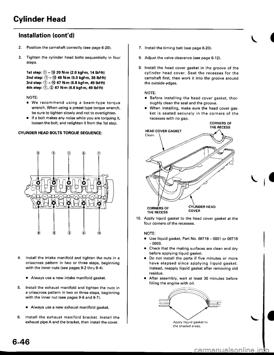
Tighten the cylinder head bolts sequentially in four
steps.
rsr st.p: O - @ 20 N.m (2.0 kgf.m, 14 lbf'ft|
2nd srep: O - @ 49 N.m (5.0 kgf.m, 36 tbtft)
3rd stop; O - @ 67 N.m {6.8 kgf.m, /r9 lbl'ft}
4th st6p: O, O 67 N.m 16.8 kgf.m, 49 tbf.ftl
NOTE:
. We recommend using a beam-type torque
wrench, When using a preset-type torque wrench.
be sure to tighten slowly and not to overtighten.
. If a bolt makesany noisewhileyou aretorquing it,
loosen the bolt, and retighten it from the 1st step,
CYLINDER HEAD BOLTS TOROUE SEOUENCE:
Install the intake manifold and tighten the nuts in a
crisscross pattern in two or three steps, beginning
with the inner nuts (see pages 9-2 thru 9-4).
. Always use a new intake manifold gasket.
Install the exhaust manifold and tighten the nuts in
a crisscross pattern in two or three steps, beginning
with the inner nut {see pages 9-6 and g-7).
. Always use a new exhaust manifold gasket.
Install the exhaust manifold bracket. lnstall the
exhaust pipe A and the bracket, then install the cover.
4.
6-46
\-
(
7.Installthe timing belt (see page 6-20).
Adjust the valve clearance (see page el2),
Install the head cover gasket in the groove of the
cylinder head cover, Seat the recesses for the
camshaft first, then work it into the groove around
the outside edges.
NOTE:
. Before installing the head cover gasket, thor-
oughly clean the seal and the groove.
. When installing, make sure the head cover gas-
ket is seated securely in the corners of the
recesses wath no gap.
COBNERS OFTHE RECESS
CORNERS OFTHE REcEss covEB
Apply liquid gasket to the head cover gasket at the
four corners of the recesses.
NOTE:
. Use liquid gasket, Pan No. 08718 - 0001 or 08718- 0003.
. Check that the mating surfaces are clean and dry
before applying liquid gasket.
. Do not install the parts if five minutes or more
have elapsed since applying liquid gasket.
Instead, reapply liquid gasket after removing old
residue.
. After assembly, wait at least 30 minutes before
filling the engine with oil.
8.
9.
I
10.