Page 355 of 2189

Troubleshooting
Troubleshooting Procedures (cont,dl
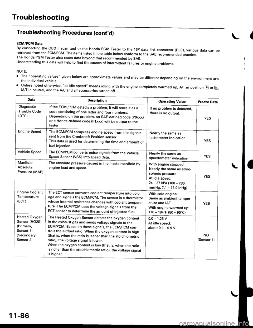
ECM/PCM Data
By connecting the OBD ll scan tool or the Honda pGM Tester to the l6p data link connector (DLC), various data can beretrieved from the EcM/PcM. The items Iisted in the table below conform to the sAE recommended practice.The Honda PGM Tester also reads data beyond that recommended bv SAE.understanding this data wil help to find the causes of intermittent fairures or engine probrems,
NOTE:
' The "operating values" given below are approximate values and may be different depending on the environment andthe individual vehicle.. Unless noted otherwise, "at idle speed,, means idling with the engine completely warmed up, Ay'T in position @ or E],M/T in neutral, and the Ay'C and all accessories turned off.
(
DataDescriptionOperating ValueFreeze Data
Diagnostic
Trouble Code(DTC)
lf the ECM /PCM detects a problem, it will store it as acode consisting of one letter and four numbers.Depending on the problem, an SAE-defined code (poxxx)or a Honda-defined code (Plxxx) will be outDut to therester.
lf no problem is detected,
there is no output.
YES
Engine SpeedThe ECM/PCM computes engine speed from the signalssent from the Crankshaft Position sensor.This data is used for determining the time and amount offuel injection,
Nearly the same as
tachometer indication.YES
Vehicle SpeedThe ECM/PCM converts pulse signals from the VehicleSpeed Sensor (VSS) into speed data.Nearly the same as
speedometer indicationYES
Manifold
Absolute
Pressure {MAP)
The absolute pressure caused in the intake manifold bvengine load and speed.With engine stopped:
Nearly the same as atmo-
spheflc pressure
At idle speed:
24 - 31 kPa (180 - 280
mmHg, 7.1 - 11.0 inHg)
YES
Engine Coolant
Temperature
(ECT)
The ECT sensor converts coolant temperature into volt_age and signals the ECM/PCM. The sensor is a thermistorwhose internal resistance changes with coolant temDera_ture. The ECM/PCM uses the voltage signals from theECT sensor to determine the amount of iniected fuel.
With cold engine:
Same as ambient temper,
ature and IAT
With engine warmed up:
176 - 194.F (80 - 90.C)
YES
Heated Oxygen
Sensor {HO2S)(Primary,
Sensor 1)(Secondary
Sensor 2)
The Heated Oxygen Sensor detects the oxygen contentin the exhaust gas and sends voltage signals to theECI\4/PCM. Based on these signats, the ECM/pCM con_trols the airlfuel ratio. When the oxygen content is high(that is, when the ratio is leaner than the stoichiometricratio), the voltage signal is lower.When the oxygen content is low (that is, when the ratiois richer than the stoichiometric ratio), the voltage signalis higher.
0.0 - 1.25 V
At idle speed:
about 0.1 - 0.9 V
NO(Sensor 1)
1 1-86
Page 393 of 2189

PGM-FI System
Intake Air Temperature (lAT) Sensor ('96 - 97 Models)
The scan tool indicates Diagnostic Trouble code (DTC) P0111: A range/performance problem in the lntake AarTemperature (lAT) Sensor circuit.
The IAT sensor is a temperature dependant resistor (thermistor). The resistance of the thermistor decreases as the intakeair temperature increases as shown below.
RES|STAI{CE {tol
. 32 .. ro. tr. 2r, zaa r..l-20 o 20 /|o ao ao 100 rrotlcl
INTAIG AIR TEMPEMTURE
- The MIL hss beon reported on.- DTC P0111 is stored.- Or from Probable C.use List.
Problem verification:1. Turn the ignition switch OFF.2. Disconnect the IAT sensor 2Pconnector,3. Remove the IAT sensor.4. Reconnect the IAT sensor 2p
5. Leave the IAT sensor exposedto ambaent temperature,6. Turn the ignition switch oN fll).7. Check the IAT with the scantool.
Rsplscg the IAT sensor.
Check tho IAT sensor output:1. Warm the IAT sensor with ahair dryer-2. Check the IAT with the scantool.
Did the IAT rise 2"F (1.C) or morefrom the ambient temperature?Int€rmittont failu.e, system is OKat this time.
Replsce the IAT sensor.
11-124
Page 397 of 2189

PGM-FI System
Engine Coolant Temperature (ECTI Sensor
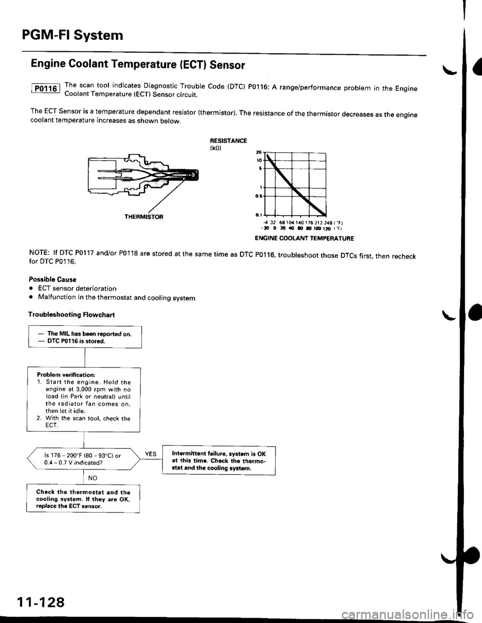
The scan tool indicates Diagnostic Trouble code (DTC) P0116; A range/performance problem in the EngrneCoolant Temperature (ECT) Sensor circuit.
The ECT Sensor is a temperature dependant resistor (thermistor). The resistance of the thermistor decreases as the enginecoolant temperature increases as shown oetow.
RESISTANCE(ko)
NOTE: lf DTC P0117 and/or P01'18 are stored at the same time as DTCfor DTC P0116.
Possible Cause
. ECT sensor deterioration. Malfunction in the thermostat and cooling system
Troubleshooting Flowchart
-a 32 68 r0a la0l?6 2t2 2481'rr-20 o 20 ao o D r@ Il, r'c)
ENGINE COOLANT IEMPERATURE
P0116, troubleshoot those DTCS first. then recheck
11-128
THERMISTOR
- The MIL has bogn reported on.- DTC P0116 is stored.
Problem verification:1. Start the engine. Hotd theengine at 3,000 rpm with noload (in Park or neutral) untilthe radiator fan comes on,then let it idle.2. With the scan tool, check the
Intermiftent lailure. system is OKai thi. time. Ch.ck the thc.mo-stat 6nd thc cooling system.
is 176 200'F {80 - 93'C)or0.0-0.TVindicated?
Check the thermostat and thecooling system. ll they als OK,raplace the ECT sensor.
Page 1476 of 2189
Troubleshooting
Schematic Symbols
BATTERY
E
@
GROGroLrnd terminal
II_d:
UNDComponent ground
II_..'-
FUSE
--cn-.e
COIL, SOLENOID
r{r
tql'|
CIGARETTE LIGHTER
A
lrl
P
RESISTOR
I
f
VARIAELE RESISTOR
ilH
THERMISTOR
c
IGNITION SWITCH
-fo o.t-
BULB
+
HEATEB
At-l
F
MOTOR
0
PUMP
H
CIRCUIT BREAKER
I
r
Yr
T
HORN
+
DIODE
+
SPEAKER, BUZZER
D
Mast
Y
ANTt:f\,NATRANSISTOR lTrl
II
SWITCH (ln niNormally open
I
/F\t tL I\Y/
I
rrdal positionlNormally closed'*i."n
@
I
LIGHT EMITTINGDIODE ILEDI
A+,
TT
RELAY lln noNormally opon relay
| ....--1'rl*r
til
t "t^f
fmal poaitionlNormally closed relay
ffl-+- |
lrl
lrl
fff
CONDENSER
I
T
CONNTInput
V
I
:CTIONOutput
J
CONNECTOR
*>-
'l!
REED SWITCH
A
tftl
Y
Page 1956 of 2189
AiC Compressor Gontrols (cont'd)
- '99-'00 Models
From page 62.
v
I*"-ilii.,"r,
ihtli4
BLUAVHT
15
6LUAVHT
UNDER.HOODFUSE/RELAYBOX
Seg Pow6rDistrlbutiofl,pag€ 'l Gl1-c353PHO|O 8
l[,,*
';.!, "'""
,c,/cSwitch switchcommon itput
a,/cTHERMOSTATOlt below3"C (37"F).
THERMISTOR
(
B11A A8A B'IO |'r--:=---I A/C lgnition B€ttery II request input (backup) :
".j:[ru*,,ry "..;X
{;[
vtEW 57
HEATERCONTROLPANEL
l'lCswitch SwitchLgD IEDcodrol cormonGrouod
See AirD€livery,RgarWindowD€foggar
BIK
cl
ORN
c5
GBN
r,/cOt'llndicatof
HEATERPUSHswrTcHEs
t/cSwltch
S€e AirDelivefy,RearWindowDslogg6f
See GroundDist.ibdion,page 1,1-5.
Y
I(
=ffi;
(
.I UNDER.
I HOODi FUSE/I RELAYI Box
IJ
62-2
PHOfO 125
Page 1973 of 2189

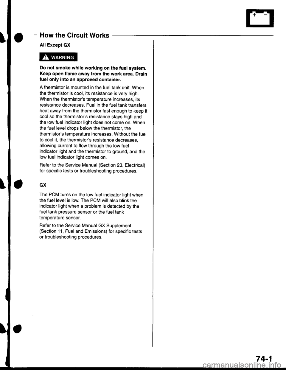
How the Gircuit Works
All Except GX
Do not smoke while working on the fuel system.
Keep open flame away trom the work area. Drain
fuel only into an approved container.
A thermistor is mounted in the fuel tank unit. When
the thermistor is cool, its resistance is very high.
When the thermistor's temperature increases, its
resistance decreases. Fuel in the fuel tank transters
heat away lrom the thermistor fast enough to keep it
cool so the thermistor's resistance stays high and
lhe low fuel indicator light does not come on. When
the fuel level drops below the thermistor, the
thermistor's temoerature increases. Without the fuel
to cool it, the thermistor's resislance decreases,
allowing current to llow through the low fuel
indicator light and the thermistor to ground, and the
low fuel indicator light comes on.
Refer to the Service Manual (Section 23, Electrical)
for specific tests or troubleshooting procedures.
GX
The PCM turns on the low fuel indicator light when
the fuel level is low. The PCM will also blink the
indicator light when a problem is detected by the
fuel tank pressure sensor or the fuel tank
temperature sensor.
Refer to the Service Manual GX Supplement
(Section 11 , Fuel and Emissions) for specific tests
or troubleshooting procedures.
74-1